Announcement

Collapse
No announcement yet.

Splitting The Positive

Collapse
X
 
  • Filter
  • Time
  • Show
Clear All
new posts

  • BroMikey
    replied
    I will have to double check but I think on the modified
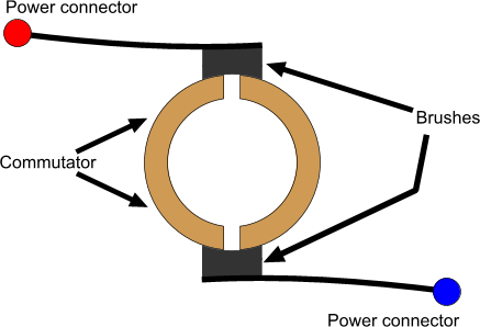
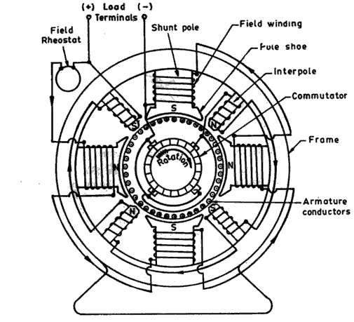
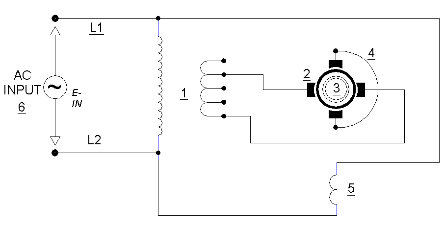
    scooter motor this is how the connections look. So how would I
    power up with only 2 brushes?

    This picture is the 4 brush motor that I already built.


    Leave a comment:


  • BroMikey
    replied
    I am doing some thinking out loud because I need to come to
    a new connection diagram for my treadmill 2 brush motor.

    If anyone knows what I need to hear please chime in stat . I have
    the scooter motor with 4 poles and I am going to post a diagram of that
    also but my main concern now is (Not being a motor designer) what is
    the best way to hook a 2 brush commutator up.

    I don't know how to hook the wires.


    Last edited by BroMikey; 07-14-2016, 09:20 AM.

    Leave a comment:


  • BroMikey
    replied
    The old motor still works but it stinks. The new motor is almost done
    I just done know if it will turn okay. It only has two brushes. Where
    the other slow speed motor has 4 brushes. We will see.

    Here is a picture of the way they look with only two long bolts
    holding them together. I used an electric die grinder once again to
    clean off the ends where copper circles back into the cage and drove
    out the copper wire.

    I also wound the wire onto the rotor and the new type of glue I am
    using this time is quick dry stuff. It is already done hardening up. Take a
    look at these beautiful motors.

    Heavy duty bears and a fan.


    Last edited by BroMikey; 07-14-2016, 06:04 AM.

    Leave a comment:


  • BroMikey
    replied
    Originally posted by SkyWatcher View Post
    Hi mike, here's the circuit diagram.
    It seems to be charging well, i have just been swapping manually every hour or so.
    If i disconnect the diode from the charge battery, the led bulb gets much brighter, so it seems to be splitting the output.
    peace love light

    Great circuit now others coming by will have something to give a try.
    Is this the whole circuit? I hate to be a nag but I was hoping for
    a full circuit. So how does the split positive hook in?

    Maybe where the 12v? So hook this to 3 batteries?

    Leave a comment:


  • SkyWatcher
    replied
    Hi mike, here's the circuit diagram.
    It seems to be charging well, i have just been swapping manually every hour or so.
    If i disconnect the diode from the charge battery, the led bulb gets much brighter, so it seems to be splitting the output.
    peace love light

    Last edited by SkyWatcher; 07-14-2016, 04:24 AM.

    Leave a comment:


  • SkyWatcher
    replied
    Hi mike, yes the TV flyback core first has 3 layers of 30 awg. magnet wire and 420 turns total.
    Then on top that, one layer of 24 awg. bifilar magnet wire, as the oscillator.
    It's a joule thief, with diode off collector going to the positive of another 12 volt charge battery and negative of charge battery, going to the joined bifilar wires.
    Then 30 awg. secondary goes to led bulb.
    If that doesn't explain it well enough, i will make a drawing of it.
    peace love light

    Leave a comment:


  • BroMikey
    replied
    If you can make a diagram I would be interested in seeing
    the entire layout. Looks like a winner


    That 'C' core drivers the high voltage to the bulb?

    .

    Leave a comment:


  • SkyWatcher
    replied
    Hi all, i finished dragons light/charger with hartley/joule thief circuit.
    Only thing different about my circuit, i don't have capacitor across base resistor and no switches yet to swap batteries.
    I tried the boost converter mode, though my gutted 3.6 watt filament led bulb did not light much at all, same with non-modified led bulbs.
    Then i wired the blocking oscillator in buck boost mode or classic SG mode and the led bulb lights very good and the flyback charging is also very good.
    Input is 4.8 watts with 12 volt tractor batteries.
    peace love light

    Leave a comment:


  • BroMikey
    replied
    Originally posted by dragon View Post
    I'm a bit "old school" so the "Hartley" that I refer to is closer to the original replacing the vacuum tube with a transistor ....Hartley patent 1,356,763
    Me too, all of the latest is based on the OLD SCHOOL or root circuit.
    I just popped in for a short and maybe I will get time to dig up those
    originals later.

    In the mean time let tell you what happened.

    Remember I ran the motor for 3 days and got my taste? I discontinued
    and went back to the UPS and there is a huge difference. I hope to
    use the old hartley and I had some really old pictures/diagrams back
    when everything was a PHOTO-COPY and teletype ruled the
    communications.

    I like it so much on the motor I striped out an old treadmill motor
    today and I am now ready to wind. But it only has 2 brushes and
    I don't know if it will work.

    I will try it and if it fails I will get 2 more brushes on it.


    http://antena.fe.uni-lj.si/literatura/VajeVT/MMIC/priprava/Hartley_oscillator.pdf


    COMPACT FLUORESCENT LAMP DRIVER
    Last edited by BroMikey; 07-14-2016, 02:21 AM.

    Leave a comment:


  • dragon
    replied
    I'm a bit "old school" so the "Hartley" that I refer to is closer to the original replacing the vacuum tube with a transistor ....Hartley patent 1,356,763

    It can be run with separate coils or split coils on a core - It's very much like a JT or blocking oscillator... there are lots of variations from the original out there because it's so versatile....

    Leave a comment:


  • BroMikey
    replied
    Originally posted by dragon View Post
    Not necessarily the bedini stuff, but this joule thief is quite efficient in recycling energy back and forth....

    Hey Dragon

    Nice circuit over on the other thread

    Maybe I will find a complete circuit somewhere, I am a bit rusty.

    oscillator I quess the SG OSC in genmode is worthless?

    A joule Oscillator? Hartley Oscillator? All warm current pulses.

    I would like to see your circuit again if I could find it here
    .

    http://www.electronics-tutorials.ws/waveforms/astable.html


    Last edited by BroMikey; 07-13-2016, 09:28 PM.

    Leave a comment:


  • BroMikey
    replied
    Hello to all

    I have repaired many many many motors in my time as a repairman
    over the past 40years and so I began to search thru my motors to
    see if I had a motor that had certain criteria to meet my requirement.

    I found one that I will share with those of you who want to use this
    motor indoors. It has the same power capacity, same approx size magnets
    with way better brush holders.

    This motor is a high quality magnet motor that can be run inside of your
    home without ever knowing it.

    Treadmill motor and it has a great flywheel, many of these electric
    treadmills are thrown out everyday and the reasons vary but usually
    the circuit or the belt rollers go bad.

    Mine are rated at 90vdc (Who care cut the thin wire off) and 5 amps
    maximum = 5amps X 90v = 450watt absolute max but running is about
    3 amps on these. The motor far surpasses most dc motors.

    Same approx power capacity. Put some wire on it like the modification
    calls for and you are good inside the house.

    Serious replicators only


    Last edited by BroMikey; 07-13-2016, 09:05 AM.

    Leave a comment:


  • BroMikey
    replied
    Hello to all

    I drilled holes in my scooter motor and it stays very cool
    however it stinks (this particular burned up motor) so bad that
    even after cleaning and painting it still fills a room with that
    nasty electrical smell with the brushes burning and so forth.

    The weather is so hot and the humidity has been near 100% for
    over a month so my work is in the air conditioning right now. I will
    set one test setup in an open outdoor area in the future to get
    more time and results.

    I have tested this modified motor (Trying to breath over it) for 3
    different days at about 4 hours per night. I have learned a lot thanks
    but these composite board brush holders and hot sparking brushes
    cause a sickening Oder that is unbearable to breath inside of a home.

    I am running the UPS circuit again and have been wondering how a
    solid state pulse circuit might look to get similar results. The tiny motor
    is great and I will continue to use it and speculate.

    For now I am running the UPS circuit across the split positive terminals
    then taking some of that energy off the charging battery sending it to
    the primaries with a cap on them.

    Keeping a balanced system takes periodic adjustment here as well.
    (where is that little green elf when you need him?)

    This keeps me going and able to breath in this enclosed environment.

    The motor gives me something to look forward to with further tests
    and at the same time maybe I can either find a better motor or
    mimic the action of the motor somehow.

    Then if a solution can be found to copy motor action in solid state
    form the booster can be connected the same way as it does using the
    motor to make adjustments. Maybe I'll go read that patent now
    and then this time I'll get more out of it.
    Last edited by BroMikey; 07-13-2016, 09:10 AM.

    Leave a comment:


  • BroMikey
    replied

    Well I am back to share tonight's connection diagram which
    like Dave said allows me to charge battery bank 3 or in my case
    a single battery for now AND tap into the charge energy.

    Like you said Dave you have to be stead after it and be sure
    that the 24v set of run batteries gets the right reflected energy
    so the pulse swing voltages go above and below on the meter that
    will average all of the numbers. Or I could bust out an analog meter
    to do the same thing.

    If I set the boost converter to low the averages drop and the 24v run
    set or primaries begin to lose voltage points. It is hard to keep a
    perfect balance with the one charge battery so I am turning on light 2
    so i can bring the voltage back down once I reach 13.95vdc. After that the
    energy builds up so fast the battery will boil and we don't want to waste
    power.

    I am going to take this motor apart and drill some holes in the end caps
    so the heat may escape that way I don't get a large build up with long
    runs. I have noticed how hot my sons scooter motor is in the middle
    of the summer on even short runs and this is weakness as far as I
    am concerned. Heat should always be dissipated while motors run
    especially such high torque units pulling around children at low speeds.

    This has me wondering where I could get a real motor to work with.

    I have gone through these batteries again(same ones) that is run
    a DC forming charge on them, run the spike mode then GENMODE at
    the end long hours to get all 3 of these batteries cooled down and
    recharged up to 16vdc til they float right up.

    The system is up and running.

    Right now it is hanging at 14.06v and watching it slowly rise so I am
    about to flip the switch on LED bulb 2 so the comes back down. In
    15 minutes I will turn it back off and repeat the process.

    Oops there goes the UPS alarm shutting down and I can't leave,
    my room stinks and I am going to drill hole thank you. It takes
    hours to get the heat up high but there is no place for it to go.


    Last edited by BroMikey; 07-12-2016, 08:53 AM.

    Leave a comment:


  • BroMikey
    replied
    Hello everyone

    i am still trying to get these batteries to float up easily, been
    to long away but I wil get there plus I have many other batteries
    floating already.

    I ordered an inverter that is real small because the only inverters
    I have are to large, it is a 750 watt 12v-110vac coming.

    The thing I have been going over in my mind are the calculations
    for these batteries. Whether watt/sec or watt/hrs I have decided
    to get these nice batteries where I know they need to be to start
    while I wait for the inverter (The UPS keeps shutting down).

    The UPS circuit is not all that efficient though calculations can be
    made just as well. For instance on my batteries rated at 28ah I
    know they are somewhat better now after conversion to ALUM
    and I have settled on a theoretical value (We will see the true value)
    of 20ah of usable power as battery ratings do not reflect the
    available energy in practical application.

    Figure about 65% of capacity and if you get more consider that battery
    to be excellent.

    To establish a baseline for a battery a discharge can reveal what your
    battery is capable of in the conventional sense, afterward the same
    set (In this case 3 battery set) of batteries can be discharged using
    the unconventional circuit layout then comparing results to determine
    if the extra has been realized.

    In my case a 20ah battery times 3 = 60ah

    A 60ah 12v battery will provide 60 hrs of current at a value of 1amp.
    In my recent UPS circuit the actual current draw to run my 10watt
    bulb AND UPS circuit losses is 1.1amps.

    1.1amp / 60ah = 55hours. This is how long my 13watt/sec load
    should run if 60ah is the correct amount. I will see just how long
    these batteries can run this little load just as I had done in the
    previous tests using the lithium batteries.

    This is the number of hours I should be able to run conventionally
    straight off the battery nothing else.

    With the split positive circuit I can see that this pumping action
    taking place in all 3 batteries while also discharging energy is a
    much better way to recirculated power. Much better for batteries.

    I am confident that many new ideas will emerge with the split
    positive circuits powering devices off of the potential difference
    between a 24vdc battery and a 12vdc battery.

    I have heard other inventors say that a standing wave on a battery
    will keep that battery charged while reflected energy can be harvested
    throughout the circuit as the energy is trapped, forever to be
    reused. It's just a matter of time before a new design will take over.
    Last edited by BroMikey; 07-11-2016, 10:37 AM.

    Leave a comment:

Working...
X