Announcement

Collapse
No announcement yet.

Splitting The Positive

Collapse
X
 
  • Filter
  • Time
  • Show
Clear All
new posts

  • Here are two great examples of non research of acceleration
    of motors under a load or which most will add a question mark
    at the end of their title.

    These guys have no clue about what is going on with a standard
    motor or a regular generator that is just like a motor. Not even a small
    picture of what they are wondering about.

    In the video the guys hook a conventional (big zero) motor to a
    conventional generator. What a joke. The 36v motor is running on
    4vdc in one of these video's. This is to create and running condition
    that is easy to listen to when any changes are made.

    In other words we can hear the motor speed up and slow down with
    any of the electrical changes being made such as resistors put into
    the line.

    The question is "WHY DOES THE SYSTEM SPEED UP?" Is this the pot
    at the end of the rainbow or a good example of bait and switch?

    To understand what happens during these tests we must know how
    motors are made and for what frequency and power level. Generators
    included.

    Motors are designed for one range of frequencies, one amount of
    current, a certain voltage where motor magic takes place. This is
    the place in the design straight from the factory called OPTIMUM.

    In magnet motor and magnet generators that are running in their
    optimized band of power/ resonance band means that for the price
    of the current and hardware a fair shake is offered in horse power to
    power a device.

    Same with generators. Running a generator off a motor is a huge
    drag. In this video like almost every video on the web the motor
    is shown to draw power after it is already connected to a generator
    that is free wheeling.

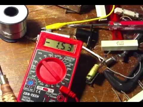
    In the video trick, the guys shows an amp reading of 1.55 amps. When
    he loads the stepper motor being used as a generator it speeds up. Of
    course it does because without the belt and the generator the motor
    will run at 750ma so as the stepper acting generator finds it's field
    creating a resonance, relief comes.

    All this video proves is that he has no understanding of how motors
    and generators are designed to run exactly where they are rated.
    Motors run as generators in open circuit create a very high voltage
    in it's coils and pose lots of drag not being designed in that range
    for that purpose.

    This is not true research. For this to be true research the experimenter
    must be aware of the current draw before the dragging generator coils
    are hung around the motors neck.

    In these video's the motors will run on half the current shown as with
    the free wheeling generator. So in this case 750ma for the motor and
    when the generator is added another 750ma. In the video a 1.55amp
    or 1550ma draw goes down a few points when loads are connected.

    Then the statements are made that they are beating Lenz law. This
    is called non research, non thinking folks who haven't got a clue
    about any of it.

    Further to state the obvious, to beat lenz or get a greater efficiency
    from any apparatus before and after measurements must be taken
    to make a determination.

    In these video's the guys are thinking they might have hit that pot
    of gold while they are only wasting more power.


    https://www.youtube.com/watch?v=_SxmlKs9C8E

    ----------------------------------------------------------------

    https://www.youtube.com/watch?v=1ccGjGw7OB8

    -----------------------------------------------------

    Last edited by BroMikey; 07-18-2017, 10:29 AM.

    Comment


    • Originally posted by Turion
      ........ remove the wire, and rewind it so that
      rather than increasing the watts per hour consumed when the coil is
      put under load, it reduces the watts consumed per hour by the motor,
      without decreasing the output of the generator coil, THAT is significant
      to me.

      ........... But I want to have an intelligent conversation about it, not be
      given hints and secret clues.
      "Good luck with that" finding someone that can find their head with
      both hands, better yet lead the best you can and they will come
      out of their programmed coma in time.


      When I strike up these conversations, I do it with a mix of the devils
      advocate, sarcastic slapstick with bludgeon revenge on the world of
      nerds who think they are leading edge. I am glad they try.

      They will all come running like the hounds of Baskerville, of course
      trying to prove the data wrong, it's that "teacher told me" stuff (yawn)

      Once I get going by cannon balling the conversation I become submersed.

      At first major thoughts escape me but after a few talks I remember what
      what I was going to say. What you have laid out for the group for
      investigative practices is good stuff basic rule of thumb for a thinking
      person. I guess the rest are not thinking.

      Now shocking results just came in. Nothing to do with reading a book,
      copy the answers so you pass, that is called cheating yourself. You got
      to get down here where we live with dirty hands. Yes rewind the coils
      right? And rewind and rewind, guess what I just found out?

      You won't find this in a book that I am aware of either.

      So I went away from standard 100-200 foot coils for generating up to
      720 feet. Because it is a multifilar winding, I can rewire the ends any
      way I like.

      1) The motor is the prime mover and draws X amount just like Turion Man
      has explained.

      2) With the addition of the weight of the rotor and magnet a greater
      amount of power is added to the initial.

      3) that is 1+1=2 for those having trouble following me

      4) Next are the coils being brought close to the rotating magnet with
      their iron cores.

      5) Going slow that is 1+1+1=3 or motor amps (1) motor and rotor
      amps(1)and motor and rotor and gencoil amps (1) each a new
      measurement.

      Now here is the place I have been trying to get. I would expect all of
      the above, that is, when I place my coil up to the rotating rotor magnets
      for the power draw to increase even without loading the coil just a static
      or idling condition.

      There is 720 feet on this coil. What surprised me is that without a load
      the system can see inside the coil when I change wiring configurations.
      For example if I put the coil setting of 3 in series and 2 in parallel WITH
      NO LOAD the system KNOWS what I have done.

      WOW. The same amount or wire and the everything else the system
      current draw will change with mere wiring patterns. For example if
      I connect all of the 120 foot wire coils in parallel in the static condition
      of no load the amp draw skyrockets. The iron core is one force to
      consider and I will try to install an empty core on the system rotor to
      see what the increases will be without wire.

      So now I connect the six 120 foot winding in series IN THE STATIC
      condition or NO LOAD. The system knows what I have done, it sees
      inside the coils and acts accordingly.

      In my case the motor cost me 1 amp to 1.2 amps running all by itself.
      Adding the rotor and running at the same 14.75vdc the current goes
      from 1.2amps on up to 2 amps.

      Now when I add a coil, in the STATIC NO LOAD condition in parallel, the
      system responds and my draw goes up to 4 amps total.

      When I take the same coils of wire, same mass and connect in series
      the additional drain only goes up 300 ma making my draw 2.3 amps

      Like you said Dave, I find this characteristics significant.

      So the system sees what winding patterns I use without ever connecting
      a load. Why does it act this way? What makes the coil in series less
      intrusive on the prime mover than the parallel coil.

      The answer is based in the delay of response to current however small,
      the parallel coils if they could be measured should show a greater
      magnetic field around them even in the static condition.

      Delaying the timing response of current to rotating magnets is the right
      direction to go in and that is what the series connection does whether
      we understand it or can explain it makes no never mind.

      So I need more feet to delay even more. I have not powered anything.
      I have a motor, a rotor and a coil that responds this way without loading.

      I am going slow on purpose so I don't get confused in the clutter of endless
      data variables. The point is that all I have done is play with the length of
      wire to understand the systems response.

      The system is telling me that the more wire I add, the less drag on the
      system will be realized. Not rocket science.

      Thanks Turion, I can't wait to see your coming genius on the 2 coil
      beginner setup, well your beginnings. Your beginnings are someone's
      life long ambitions.
      Last edited by BroMikey; 07-18-2017, 11:07 PM.

      Comment


      • Turion,
        Thanks for sharing all this VERY good stuff.
        I'm one of those idiots still using 7.2ah batts, lol, but I'm just about to invest in proper 100ah deep cycles. Once I have these new batts do they need "conditioning" as in, completely drained till the bulb goes out, then pulse charged, and repeat x10?
        Thanks,
        Mark

        Comment


        • Originally posted by Turion
          The bone of contention I have is with the folks that go on YouTube
          to make videos to prove this DOESN,T work and are running loads far
          in excess of the C-20 discharge rate of the batteries and are using
          small batteries that have incredible resistance to being charged.

          There is literally NO margin for error when you are working with small
          systems trying to do this stuff and those people are dead in the
          water before they even START.

          Here is another brainstorm I picked up somewhere. Also people
          need to follow a seasoned leader instead of wandering around aimlessly
          trying to reinvent all of the wheels. Save yourselves the trouble and
          be a hero for you first.

          We need some Indians and not all Chiefs, most of you have no idea
          how to get any extra watts out of any device so go ahead an admit it
          or show us one.


          Comment


          • Originally posted by Turion
            Mark,
            No. Draining them and pulse charging them is going to knock the sulfation off the plates so eventually they will hold more and last longer, but you don't need to spend the time doing that.

            And please understand, I have no problem with the folks who try running on the potential difference using small batteries to see if you can actually do it or not. Everybody has to get their feet wet and not everyone jumps in the deep end first. The bone of contention I have is with the folks that go on YouTube to make videos to prove this DOESN,T work and are running loads far in excess of the C-20 discharge rate of the batteries and are using small batteries that have incredible resistance to being charged. There is literally NO margin for error when you are working with small systems trying to do this stuff and those people are dead in the water before they even START.

            Dave
            Thanks - understood. I certainly know what you mean about zero margin for error with the small batts. I have seen a total gain by using the 3-batt system and my stingo circuit, but only a small margin, like a few 100ths of a volt after 4 hours of rest of the batts. I expect that to increase with bigger batts. Cheers.

            Comment


            • Originally posted by moflint View Post
              I have seen a total gain by using the
              3-batt system and my stingo circuit, but only a small margin, like a
              few 100ths of a volt after 4 hours of rest of the batts.


              Doesn't sound very good a few hundredths of a volt when we are
              talking about extending the run times.

              Here let me start fresh, run a pulsing or switch mode inverter on a
              battery and count the joules up. Next recharge your batteries.

              Now run between the positives as shown in the diagram BUT, BUT
              never exceed the C20 rate. Now you have done it already, you have
              extended the run time because you have negated 99 percent of the
              resistance losses than when batteries are drained improperly.

              Next go back to your conventional setup with just an inverter from
              a battery pack and run at the C20 rate as you were instructed. Unless
              you add that in I will assume you need to be rereading what is being
              said here.

              Okay so if you or anyone else is going to throw out a few loose
              statements, be sure you will asked if you followed procedure. A
              return answer of "YUP" is inconclusive.

              Now run the tests in this way as shown never going beyond the
              batteries rated C20 charge and discharge curves. Withe your 3ah
              battery you will only be able to discharge 65 percent of it's total
              power so as not to destroy it. So that is a 2ah battery in practical
              terms.

              Unless you understand your batteries and the systematic approach
              required to follow these instruction, you will be lost and fail as you
              have been doing. Or maybe you think so.

              Now 2ah = 2000mah divided by 20 hours means your batteries
              can deliver 100ma to the inverter/charger/booster/charger/whatever
              it is you have. Also you must create and maintain a potential difference
              in voltage that will send a current thru the inverter to the charge bank
              not exceeding 100ma.

              You may need very small circuit such as a 99 percent efficient car
              charger that is the size of your thumb to stay in range of such a small
              ma rating and remember you are going to need half of that to run
              your supervisory section. So find out how much it eats and give that
              as a freebee into your calculation.

              Actually I just showed you that even with your 65 percent charger
              stingo charger circuit you are getting more than normal. This is why
              you get fooled, because you don't realize how inefficient such a small
              system is when half of the minuet amount of power is lost to LED's
              or resistors from a poorly engineered toys.

              To make the test properly that is, or give it up. This thread is about
              splitting the positive using properly rated devises and not exceeding
              the C20 rates. The stinkgo or other circuits I am sure are good for
              something like learning to built boosters.

              Stick to protocol and if not that is fine too, just don't try to compare
              what is being shown here with your concoctions. Give the rates of
              discharge or other details that gives us an idea that you understand
              your batteries and circuits you are using.

              The answer is yes, you are getting the extra but don't realize that
              the figure you are getting is way higher because you have not counted
              your inefficiency losses.
              Last edited by BroMikey; 07-25-2017, 08:23 AM.

              Comment


              • Originally posted by BroMikey View Post


                The answer is yes, you are getting the extra but don't realize that
                the figure you are getting is way higher because you have not counted
                your inefficiency losses.
                Yes - I have proved the split-positive system works, at least to myself, now I have to improve on efficiencies such as swapping to bigger batteries, thicker cables etc.

                Thanks for all the great stuff you've shared in this thread.

                Mark

                Comment


                • Originally posted by moflint View Post
                  Yes - I have proved the split-positive system works, at least to myself, now I have to improve on efficiencies such as swapping to bigger batteries, thicker cables etc.

                  Thanks for all the great stuff you've shared in this thread.

                  Mark
                  You are very welcome Mark. You are a winner. The info comes directly
                  from certain men who have been in the field for decades. I am just
                  a parrot most of the time. Sometimes I verify good results also.

                  A happy parrot I might add. Happy to have such great men to follow.

                  Keep us in the loop on your progress

                  Comment


                  • Originally posted by BroMikey View Post
                    You are very welcome Mark. You are a winner. The info comes directly
                    from certain men who have been in the field for decades. I am just
                    a parrot most of the time. Sometimes I verify good results also.

                    A happy parrot I might add. Happy to have such great men to follow.

                    Keep us in the loop on your progress
                    Thanks BroMikey. We all stand on the shoulders of those who came before us, who also stood on the shoulders of their predecessors. The greatest gift we have is to discern the truth when we see it, and go where it leads.

                    Comment


                    • Originally posted by Turion
                      moflint,
                      Are you running much of a load on the 3 battery system? It really is not designed to "gain" anything, simply to run the load for 'free." Not even with BIG batteries. Just the bigger the batteries and the more amp hours you have to work with, the larger the load you can run. But NEVER any real gains. Just maintains steady.
                      No - I did not run a load at all. I ran a (modified) dual stingo circuit for about 45mins, drawing aprox 2amp at 12v (24v to 12v split positive). I measured the total battery voltage before the run, and had not used the batteries for about 24 hours prior to that. After the run I disconnected all leads and let the batts sit for 4 hours. At this point there was a slight gain in the total batts. These are little 7.2ah batts, rather abused! 6 batts: 2 x 12 for 24v, 2 x 12 for 12v, and 2 x 12v for 12v being pulsed by the stingo.

                      It's fairly pointless I know, no load, no point! But at least it demonstrated to me that a gain occurred PLUS the recycled energy added to it made the whole system slightly more than 100% efficient. There are real losses in charging batteries (especially mine!) and running that circuit at 2amps for 45 mins. I am sure the gain would have been greater with better batteries.

                      This test was a few months ago. I've been concentrating on a small Adam's motor since then because I think a motor holds more promise due to the extra power on the shaft. I have not investigated your scooter motor yet as I've only just found this thread - but I'll take a good look over the next few days.

                      Thanks for sharing your hard earned experience!

                      Mark.

                      Comment


                      • I will take a look at the modified scooter motor. I'm interested to see how the timing is handled. On my dual pole motor I've tried both hall sensor, and trigger coil setups. I believe the trigger coil gives a more "negative" spike than the hall sensor, but not sure which, if any, is better for batteries in the long term.

                        Comment


                        • Well, I kinda hope you stick around and do the vid, lol. But everyone needs some downtime :-)

                          Comment


                          • Correction

                            Originally posted by moflint View Post
                            No - I did not run a load at all. I ran a (modified) dual stingo circuit for about 45mins, drawing aprox 2amp at 12v (24v to 12v split positive). I measured the total battery voltage before the run, and had not used the batteries for about 24 hours prior to that. After the run I disconnected all leads and let the batts sit for 4 hours. At this point there was a slight gain in the total batts. These are little 7.2ah batts, rather abused! 6 batts: 2 x 12 for 24v, 2 x 12 for 12v, and 2 x 12v for 12v being pulsed by the stingo.

                            It's fairly pointless I know, no load, no point! But at least it demonstrated to me that a gain occurred PLUS the recycled energy added to it made the whole system slightly more than 100% efficient. There are real losses in charging batteries (especially mine!) and running that circuit at 2amps for 45 mins. I am sure the gain would have been greater with better batteries.

                            This test was a few months ago. I've been concentrating on a small Adam's motor since then because I think a motor holds more promise due to the extra power on the shaft. I have not investigated your scooter motor yet as I've only just found this thread - but I'll take a good look over the next few days.

                            Thanks for sharing your hard earned experience!

                            Mark.
                            I realised that I'm using a slightly different "3 battery system": I am splitting the positive with a common negative across 2 batts (or batt BANKS) but then the coil collapse/switch event pulse is going to a 3rd bank. This is what I did with my test when there was a slight gain in the batts - however the only load was the actual pulser (stingo) circuit. Here is a diagram attached.
                            Attached Files

                            Comment


                            • Originally posted by moflint View Post
                              I realised that I'm using a slightly different "3 battery system": I am splitting the positive with a common negative across 2 batts (or batt BANKS) but then the coil collapse/switch event pulse is going to a 3rd bank. This is what I did with my test when there was a slight gain in the batts - however the only load was the actual pulser (stingo) circuit. Here is a diagram attached.
                              Humm... You got me on that one, better let an experienced
                              professional take your example into consideration. I don't comment
                              unless I can be sure I would be telling you correctly.

                              Thanks and keep us up to date. Turion will chime in on his handheld I
                              am sure, he is rich.

                              Comment


                              • Originally posted by Turion
                                Hard for me to say, since I do not know what the "stingo" circuit looks like. So hard from to tell how it fits in. If it is a simple bifilar coil charge circuit, I'm not sure what is used as a pulse, or where that is in the circuit. We have been discussing, and BroMikey posted a schematic for running either a motor or an inverter between the positives with a charge circuit in parallel that has its output going to a third set of batteries. I know that works, and I would say that if you are using a charge circuit that pulses a coil between the positives and takes the output of a bifilar coil to a third battery bank, you use SO LITTLE AMPS with a circuit like that, that the battery can recover on its own, and the coil collapse of the primary charges one group of batteries while the voltage induced in the second wire charges the third set of batteries. It proves the point, but once you increase the size of the coils to get useful work, you will probably pull too many amps out of the batteries. Once again, it is the small batteries with high resistance that are going to be the issue.

                                Again, I don't know how the whole circuit is put together or what parts are in the stingo circuit, so I'm just guessing. Since it appears you are doing something a little different, I would advise you to take careful notes and if it WORKS, don't FIX IT!
                                I posted the diagram not as a recommendation but just to clarify what I did to avoid any confusion with the "standard" config here. And to confirm splitting the positive is actually very awesome! I didn't cycle any of the battery positions and I doubt it would have made a working system as I had no dc boosters in it to balance charging for cycling round. I might resurrect this experiment now I have the dc booster info, but I'm pursuing the motor route because I think that motors offer an extra source through the permanent magnets and easier to multiply out by adding more litzed windings to the coils. I've some mods to make to my motor and will post results when I'm back testing. Cheers.

                                Comment

                                Working...
                                X