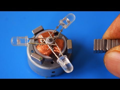
A caring guy conducted a demonstration experiment for me with a simple generator. For which I am very grateful to him!
Video clip: https://www.youtube.com/watch?v=yOq1TN3lnIo
My updated theory is fully confirmed. My analysis is on the slide, if you can read the formulas, everything can be seen in the palm of your hand.
I have already been asked questions about the motor that I described in the article. I will do a full analysis and methodology in the manual.
2021-12-09_194504556.jpg
-
Thank you Mr Rakarskiy
I can see in English.
This is alot of math to prove out that most people here can not perform.
Last edited by BroMikey; 12-07-2021, 05:23 PM.Leave a comment:
-
https://rakarskiy-narod-ru.translate...en&_x_tr_hl=ru
http://rakarskiy.narod.ru/_ld/0/40_Electromechanic.pdf
edit later - technical translationLast edited by Rakarskiy; 12-07-2021, 06:21 AM.Leave a comment:
-
My material is about the possibilities of electro-mechanical (electromechanical) converters
Some will turn their brains upside down, some will not be able to finish reading the first part. Alas, there is no point in reading without basic knowledge.
The material in Russian / through a translator can be read
The first part: http://rakarskiy.narod.ru/publ/free_...cepi/3-1-0-139
The second part: http://rakarskiy.narod.ru/publ/free_...rque/3-1-0-138
The third part: http://rakarskiy.narod.ru/publ/free_...otor/3-1-0-140
Quote:
Still, ask "why does the motor have this result". Let's look at the peak ampere strength in the generator winding and the active motor winding:
Generator: peak Ampere force of 128.86 Newtons (excluding electromagnetic focal thrust) with a thickness/length of the rotor along the axis of 74 mm (1.5 kW of electrical power)
Motor: peak Ampere force of 271.55 Newtons with a thickness / length of the rotor along the axis of 158 mm (0.396 kW of electrical power). How did it happen?
Understand, everything is in the material, I think there is enough material to just think about whether we know everything about electromechanical converters.Leave a comment:
-
could be might be experimental bench work play time, lots of magnet engines do
Leave a comment:
-
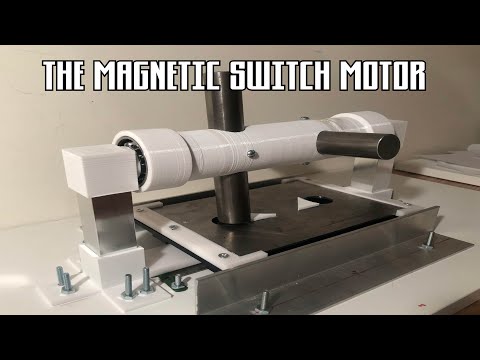
Motionless Switching Magnetosphere Electric Generator
This Generator is designed in the shape of the Magnetosphere.
The core of the generator has a common switching coil(electromagnet) with
two large permanent magnets on each side of the coil. There are fins
around this core. There will be several fins around the core so that
the assembly will look like a sphere. The fins have permanent magnets
spaced out in the fin in such a way to move flux from one magnet to the
next magnet in the fin and then through the core finally flowing
through the fin again. One the outside of the permanent magnets in the
fins are coils. The coils are spaced farther from the permanent magnets
so that the normal flux flow moves from one permanent magnet to another
producing one large ring of flux flow using the core as part of that route.
The magnets and coil in the core are larger that the fin magnets so that the
core can handle the travel of the sum of flux flow from all of the fins in
the generator.
This generator design is different than the Sphere Generator I have already
designed because it uses permanent magnets in the core rather than
core material. I believe the permanent magnets will provide better
assurance that the large ring magnet function will work. At least it should
work better than core material. Also, there is only one coil per permanent
magnet in each fin rather than more coils in the sphere generator. The
reasons for this change are that having one coil outside the permanent
magnet means it is farther away from the core, this will reduce negative
interaction between the fin coils and the core magnets. This design
will also allow more fins to be placed into the generator. More fins
means more power generation. The coils in the fin need to be large
enough to handle the flux that will be moving through the coils.
The operation of the generator is about the same as the sphere generator
I have already designed. This new design will operate with more power
and efficiency.
The way this generator operates is that each fin assembly works in conjunction
With the common core assembly. The normal flux flow is of each fin is through
the core creating a large ring magnet. So, the generator will have several large
ring magnet actions being performed at the same time.
There is one large coil that has a core that supports all of the flux flowing
Through its core when the power is off to the generator. Once the power
Is turned on to the coil, the coil produces a magnetic field that opposes
The direction of flux flow through the core. What this does is it breaks
The large flux ring flow of the flux for each of the fins. The flux then
Looks and fins the next easiest route for the flux to flow. Most of the
permanent magnets in the ring will then start to use the core in the coil
that is closest to it in the fin assembly to travel through to get to the
other side of the permanent magnet. The reason it takes this route is
because the core material is an easier path than an all-air path to get to
that side.
The electric power generation is performed through the coils that are
Beside the permanent magnets in the fin assemblies. The is wire wrapped
around the coils cores that will have electricity flowing through them
as a result, change in flux movement. In fact, there is flux either starting to
flow through the coils or reducing their flux flow with each change in the
electrical condition on the one electromagnet at the center of the generator
core. With the best switching speed for the generator, it means that the
electromagnet can operate at a 50% duty cycle while each coil in the generator
can collect alternating current 100% of the time. So, the generator uses one switching
electromagnet operating at a 50% duty cycle to be able to collect electrical
energy from several coils at the same time.
The electrical energy to produce a magnetic field for a 50% duty cycle in this
Generator should be a lot smaller than the several coils producing electrical
Energy from the several permanent magnets that are changing their flux
Routes. This is similar to a FET or transistor where a larger amount of energy
is being controlled by a smaller one.
Please build one of these, you will be glad you did.
I have written three books on unique generator and motor designs along with several applications for them.
It has come to mind that the best invention would be a generator that does not need outside energy to operate it.
This generator design utilizes the internal power that is already in permanent magnets.
This is my best design so far.
Drawing zzz.jpg
Once you have free electrical energy production, then the efficient motor designs I have are not as valuable because you can still
use the current ones. But if you want an electric car that never needs to be plugged in, then I would still pursue
the motor designs in my books sold through kindle direct publishing.
LunksterLast edited by Lunkster; 12-03-2021, 06:26 PM.Leave a comment:
-
Hate to rain on this but in post 2240, if you watch the revs of the flywheel, it does slow down. At the end it is going quite a bit slower. I would have to see this rig run for a straight say 5 hours, then I would call it true. Lots of guys in India have build these and tried to pass them off as full runners.
thay
Leave a comment:
-
I think it a series load sharing. my batteries got more straight off them without all that pumping in a circle. the circuits or converters eat power and batteries offer resistanceOriginally posted by Turion View Post
i have not found the magic freq and the mod motor runs it down faster and a block transformer must be use to recharge the dying batteries asap
always hanging on the edge of your seat as the entire sets of all of the very expensive batteries creep downward a few points at a time as sufation over runs the plates hour after hour never seeing a self sustaining moment.
hand over mouth the experimenter must resort to a 2.5x charging ratio forcing the packs to go back up using conventional means
2000lbs of the right batteries might be sprinkle charged at low resistance? something in the range of .02 or .003 points on the full scale? interesting at best.Last edited by BroMikey; 12-02-2021, 02:42 PM.Leave a comment:
-
here is a single phase motor 4 pole with all coils in series. also known as split phase motors because the start and run series windings are fired to start and assist the run winding at a specific angle. the coil orientation connection is alternated N S N S but always in series.
these rotors do not have magnets so I am not sure but I see it now
Originally posted by Turion View Post Last edited by BroMikey; 12-02-2021, 07:28 AM.
Leave a comment:
-
Bi is correct. Six groups of 2 coils each. And an even number of magnets on the rotor. So all 12 coils are presented with a magnet at exactly the same time. Single phase.
The last machine I built, that had all N magnets on the rotor was a five phase machine because it had five pair of coils but an even number of magnets on the rotor so only two coils (one pair) was ever presented with magnets at the same time. But all N magnets did not produce NEAR as much energy in the coils as N/S magnets did, so that $2,000.00 is sitting in the bottom of my trash can right now, and will go out to the garbage on Friday. I was cleaning up my shop today, and as much as it hurt me mentally to throw that thing away, it does me no good, and I have GOT to make room in my shop for new projects.
Does anyone here believe that any of the energy that passes through the load on the 3 battery system is actually recovered, or does everyone believe that the load is just "in series" with the third battery, each get a "share" of the energy that comes out of the two batteries in series, and no energy is actually recovered. If you believe energy CAN be recovered, then free energy is possible. If the Tesla switch works, (same principle) then free energy is possible.
Or dos everyone believe that energy is ALWAYS "converted" by the load into some other form, be it mechanical, heat, etc. .
Just curious what people think after all this time. After all the opportunities folks have had to find out for themselves.Last edited by Turion; 12-02-2021, 06:50 AM.Leave a comment:
-
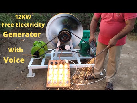
Good time! Unfortunately, there is no clear understanding of the flywheel operation in the kinetic chain in this document. The flywheel cannot operate continuously, providing a stable level of accumulated torque on the shaft.Originally posted by BroMikey View Post
With the help of a flywheel, the power of the drive motor can be reduced only with the variable nature of the kinetic load. In the generator, such a load is an electromagnetic moment.
Modern generators are designed just taking into account the alignment of this indicator so that it is more or less stable on the shaft. Modern generators will slow down the flywheel very quickly. (By the way, Bedini showed how to solve this problem in the simplest version, in order to have only one half-period rectification, the second half-period is not activated for the circuit to work).
With the flywheel, there is only one option: the acceleration period without starting the generator and the sampling period using the power control of the selected power. (For example, study how the American system from IE company "Earth Engine" works.
https://e-catworld.com/2019/05/19/de...ol-of-entropy/
My material, in it I just found which company demonstrated the generator at the presentation of its MODEL 30. https://rakarskiy.livejournal.com/12789.htmlOn the laboratory device "Crystal" you can see the operation of the damping device every 360 degrees. It consumes an average of about 20 watts per shot.
The crystal is equipped with a 100-watt alternator, rectified to 24 volts. It is also controlled by a magnetic drive.
The crystal was built SOLELY to prove the applied science of magnetic motion. The simple fact is that two magnetic fields create a force, and when they are assembled, this force can rotate the flywheel. This flywheel can then charge the battery or capacitor.
So, here are some very important facts;
1.) The crystal is not a dynamic motor. Magnetic traction is not dynamic (instantaneous) in its strength. This is inertia. It provides energy (which can then rotate the generator) by accelerating the flywheel and accumulating this energy. It is not possible to connect the dynamic load to the magnetic motor. It will just stop, and it will stop quickly.
2.) Magnetic propellers work by creating inertia in a very specialized flywheel (about 257 parts), which refuses to magnetize in the presence of a large and powerful magnetic field. After the speed (125 to 350 rpm) you have a great way to collect kinetic energy by rotating the generator. The generator is not allowed to exceed a certain load, based on its effect on inertia. It is also a highly classified trade secret. Think of it as a very large electric "pump".
3.) Magnetic traction requires STORAGE. Battery or capacitor. You can charge 24 hours a day, seven days a week.
4.) Magnetic traction requires a BATTERY or a CAPACITOR for parasitic energy to start the attenuation section. But it's only about 20 watts per second at 60 rpm. So the battery is very small.
5.) The Crystal flywheel weighs 622 pounds, while our commercial engine flywheels weigh just over 4,000 pounds.
6.) Magnetic motion is not a "superblock" and not a perpetual motion machine. It gets its energy from a pressure of over 5,000 pounds per square inch of accelerated magnetic field. The magnetic fuel I have developed has an "attractive force" (a common measure used in magnetism) exceeding 10,000 pounds. This type of force requires not only great security measures, but has also led to great breakthroughs in handling these very powerful magnets.
14992_800.jpg
https://youtu.be/vRsBGGxEOdk
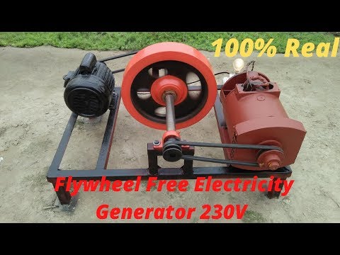
The company from which the generator was purchased has only one published patent US9444294B2, Where all the internal features of their generators are shown - multiphase and control of the removed power.
24433_original.jpg
Power take-off, at certain intervals. Magnetic torque generator - exomechanical effect "Output power is greater than input".
An exomechanical effect occurs when two energy sources (static and/or dynamic) are exposed to the same object.
This is not in itself an excessive unity. The advantages of using exist only when the magnetic torque is higher than the torque of the primary motor.
I know. what I'm talking about, I had experience creating a similar model. This is a very jewelry engineering art.
Therefore, what is issued in an American company as a trade secret, for me everything is visible in the palm of my hand.
In the video, there is just an episode of checking the system that when the motor and generator are closed in the ring in an overclocked state. The system will stop anyway, which is demonstrated in the video. In order for it to work, you need to have an accurate understanding of the algorithm of the periods of switching on and off the generator.
https://www.youtube.com/watch?v=kjdquk-LLSI
Leave a comment:
")

Leave a comment: