If this is your first visit, be sure to
check out the FAQ by clicking the
link above. You may have to register
before you can post: click the register link above to proceed. To start viewing messages,
select the forum that you want to visit from the selection below.
Motionless Switching Magnetosphere Electric Generator
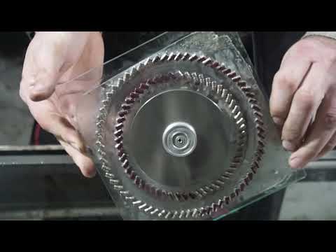
This Generator is designed in the shape of the Magnetosphere. The core of the generator has a common switching coil(electromagnet) with two large permanent magnets on each side of the coil. There are fins around this core. There will be several fins around the core so that the assembly will look like a sphere. The fins have permanent magnets spaced out in the fin in such a way to move flux from one magnet to the next magnet in the fin and then through the core finally flowing through the fin again. One the outside of the permanent magnets in the fins are coils. The coils are spaced farther from the permanent magnets so that the normal flux flow moves from one permanent magnet to another producing one large ring of flux flow using the core as part of that route. The magnets and coil in the core are larger that the fin magnets so that the core can handle the travel of the sum of flux flow from all of the fins in the generator.
This generator design is different than the Sphere Generator I have already designed because it uses permanent magnets in the core rather than core material. I believe the permanent magnets will provide better assurance that the large ring magnet function will work. At least it should work better than core material. Also, there is only one coil per permanent magnet in each fin rather than more coils in the sphere generator. The reasons for this change are that having one coil outside the permanent magnet means it is farther away from the core, this will reduce negative interaction between the fin coils and the core magnets. This design will also allow more fins to be placed into the generator. More fins means more power generation. The coils in the fin need to be large enough to handle the flux that will be moving through the coils.
The operation of the generator is about the same as the sphere generator I have already designed. This new design will operate with more power and efficiency.
The way this generator operates is that each fin assembly works in conjunction With the common core assembly. The normal flux flow is of each fin is through the core creating a large ring magnet. So, the generator will have several large ring magnet actions being performed at the same time.
There is one large coil that has a core that supports all of the flux flowing Through its core when the power is off to the generator. Once the power Is turned on to the coil, the coil produces a magnetic field that opposes The direction of flux flow through the core. What this does is it breaks The large flux ring flow of the flux for each of the fins. The flux then Looks and fins the next easiest route for the flux to flow. Most of the permanent magnets in the ring will then start to use the core in the coil that is closest to it in the fin assembly to travel through to get to the other side of the permanent magnet. The reason it takes this route is because the core material is an easier path than an all-air path to get to that side. The electric power generation is performed through the coils that are Beside the permanent magnets in the fin assemblies. The is wire wrapped around the coils cores that will have electricity flowing through them as a result, change in flux movement. In fact, there is flux either starting to flow through the coils or reducing their flux flow with each change in the electrical condition on the one electromagnet at the center of the generator core. With the best switching speed for the generator, it means that the electromagnet can operate at a 50% duty cycle while each coil in the generator can collect alternating current 100% of the time. So, the generator uses one switching electromagnet operating at a 50% duty cycle to be able to collect electrical energy from several coils at the same time. The electrical energy to produce a magnetic field for a 50% duty cycle in this Generator should be a lot smaller than the several coils producing electrical Energy from the several permanent magnets that are changing their flux Routes. This is similar to a FET or transistor where a larger amount of energy is being controlled by a smaller one. Please build one of these, you will be glad you did.
I have written three books on unique generator and motor designs along with several applications for them. It has come to mind that the best invention would be a generator that does not need outside energy to operate it.
This generator design utilizes the internal power that is already in permanent magnets.
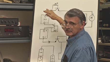
This is my best design so far. Drawing zzz.jpg Once you have free electrical energy production, then the efficient motor designs I have are not as valuable because you can still
use the current ones. But if you want an electric car that never needs to be plugged in, then I would still pursue
the motor designs in my books sold through kindle direct publishing.
John Bedini sold the Tesla Switch kits consisting of relayed energy thru mini converters. A motor gets the energy from a series of batteries that keep themselves charged
I analyzed the experiment more deeply and found inaccuracies in determining the magnetic induction of a magnet in the wire area.
My method is very correct, I am very happy about it.
The magnetic induction of the magnet can be calculated on this page:
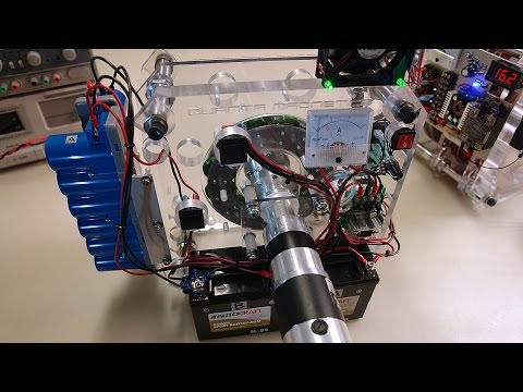
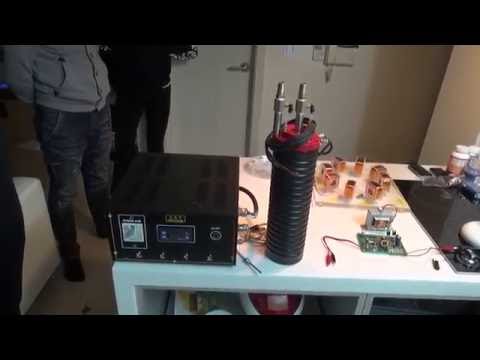
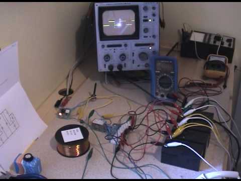
Here is the split positive generator system on a watt meter in constant battery voltage decline until the death of the batteries
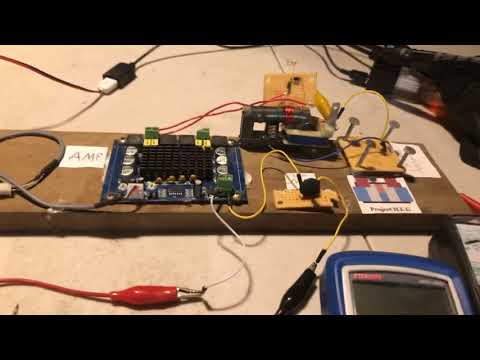
this mod motor was tested as well also using various timings
other than my video's no one on the internet offers any work with split positive charging of 3 battery systems. I have been here for years and there is no response. no one watches or knows what it is, same thing.
however people have suggested the idea but have no hardware, just talk and fear of nda
Dave has shown the scooter motor taking power from 1 bank and charged another bank claiming a non surface charge increase but quickly removed it all due to negative comments on youtube and has since turned off that function. Dave insisted he is getting more into his big pack of 10-12 large batteries than is being used. His proof in a high dollar battery analyzer $5000 one that give an accurate accounting of all joules in a battery.
Of course this is hearsay and no one has any real examples other than a video Dave once posted of a run pack going up higher due to the use of a shorted battery he say could not be repeated.
This is a great mystery to Dave who is frantically trying to recreate this glorious phenomena. The years have past and other pressing matters have stood in the way of this idea.
only bye has a 1 battery system tube video that shows nothing just like the 3 battery video's I show. over the years I have been ignored, spit on and degraded for showing my results. calling my work inferior or blaming hardware. Shame on me for not spending endless year of bench work to find out what the NDA's have shown others who hide any direction for fear of prosecution. but the creation of energy we are told is real.


Leave a comment: