I thought it was cycles per second, as in both a NORTH and a SOUTH = a cycle. Is one magnet hitting the coil a cycle, or is it a North and then a South hitting a coil to make a cycle?
Just asking. I have no idea.
-
This is how frequency is determined.Originally posted by Turion View Post
24 magnets cycling at 2800rpm =24 X 2800 = 67,200 times per minute the flux will strike a single coil core. But you want frequency, not pulses per minute so for this we need to go to a per second number. To do this divide 67,200 per minute by 60 seconds because we know that for every minute of time there are 60 divisions.
67,200 divided by 60 = 1120 pulses per second also known as 1120 cycles per second or 1120hz. Each section of core material found inside each coil gets struck by the same number of pulses as all 24 magnets pass by.
Therefore each of your generator coils will produce 1120 hz AC
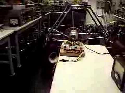
For fun I am throwing in 2 video's (some old footage)
 Last edited by BroMikey; 03-29-2022, 08:35 PM.
Leave a comment:
-
Another thing to consider is you could have 24 magnet rotor with 7 coils on each side of the rotor (14 coils). The frequency would be 7x24 = 168 x rpm. And you have to match your voltage to that.Leave a comment:
-
I buy my cores from these guys and charts tell you how many turns of awg wire size for a job. call them they help
https://www.bridgeportmagnetics.com/...-transformers/
https://www.bridgeportmagnetics.com/...-transformers/Last edited by BroMikey; 03-29-2022, 11:37 AM.Leave a comment:
-
Unless I am way out to lunch, the V/f ratio is what must remain constant, so a 60hz or 100hz transformer can be used as long as you wind the COIL to produce the correct voltage for the operating frequency. Even if you get everything wrong, all that happens is losses and heat. You still get usable output from the transformer. But then, I'm no expert.Last edited by Turion; 03-29-2022, 07:58 AM.Leave a comment:
-
Not using transformers rated at 60hz you can't. A toroid wound right maybe but I am not sure you can do that. The right toroid core rated at 2000hz could be wound for step up or step down. Hanging a 60hz transformer on it won't help you so converter first yesOriginally posted by Turion View Post
Sounds like bad trouble running with the wrong crowd.Last edited by BroMikey; 03-29-2022, 02:45 AM.Leave a comment:
-
We have discussed the coils. It is really the watts output per coil that matters, not the volts or amps. Everything can be run into bridge rectifiers, converted to DC and then stepped down to 12, 24 or 48 volts. Or you can first run through an AC transformer to up the amps and step down the voltage and then bridge to DC.
I much prefer solid dependable DC output with plenty of amps because it can be used to charge my battery banks or run inverters. AC output that is NOT at 60 Hz can be problematic if you try to run some things directly with it. Warranty voided!
I can see that a 1” by 1” N52 magnet and a 1” diameter coil core would probably produce all the volts and amps we are looking for with the correct coil. I am looking for bobbins with that size core now as I wanted to try the bigger core anyway. I am really curious to see what size magnet and then what size coil core it will saturate.
I guess it’s time to do some research. I am sure that specific core materials probably have formulas for saturation, especially if they are designed as core materials. You have to saturate the core before you can wind a coil that will put out max power for the specific magnet and core mass (quantity) that you have. A magnet that is too small for your core doesn’t get the job done and one that is too big gets you no “extra” volts or amps.
$325.00 a month x 12 months x however many years plus an extra $100 every year I got from my in-laws at Christmas has been my operating budget, so I’m probably at the $50,000 mark now. But that includes lots of equipment I have bought for my shop that has gotten used on tons of other projects from Bedini motors to Benitez style Tesla switches, woodworking projects and cabinet making. Desktop CNC machines and 3D printers. It has kept me busy and out of trouble I know I would have gotten into otherwise. Big trouble. Life changing trouble. LOL.
Leave a comment:
-
Sounds like you will be getting your answer so the new cores will work instead of all that heat. BTW Thanes rotors use 1" dia magnets by 1" long. However I would like to add he runs 3600-3700 rpm and targets 70vdc with higher amps such as 3-5amps per coil. So half the voltage you run and twice the amps. Thanes coils may be able to go to 5amps but 3 amps all day long is better for those specific designs. You never run max values.Originally posted by Turion View Post
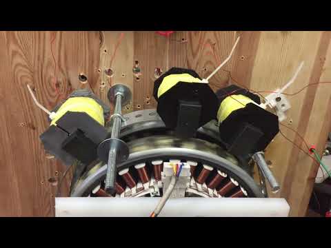
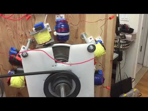
This is food for thought only. Thane is always changing coil sizes to see what is possible. See the last pictures I posted of his 3 coils that are various sizes. It seems that this type of coil is the same length for everyone at high speeds.
Longer coils give high voltages and sacrifice Amps. Sorter coils give less volts and much higher amps. It may be better to run higher amps, I can explain why.Last edited by BroMikey; 03-28-2022, 11:21 PM.Leave a comment:
-
Thanks Dave regardless of our differences you have always come thru with the bacon, sharing your progress and hard knocks. For that you have my respect. You are so blessed to have people helping you and based on your post have a new adventure ahead of you even if the old units were somewhat disappointing.Originally posted by Turion View Post
Your new setup sounds great to me and this is exactly what THANE HEINS did for years. In his first 10 years of testing all you see is another bench grinder with rotor magnets, sometimes dual rotors. If you are not careful you will end up spending $100,000 in total after all these years like he did.
I know how it must feel with the new machine being a failure. That's to bad, I am sorry to hear that. I wish you could use the rotor to connect to a bench grinder but then you wouldn't be be able to put it together again.
Update: My open heart surgery is healing fast, it has been almost 3 weeks and now I sleep most of the time. Blood pressure is awesome, just have to readjust.Last edited by BroMikey; 03-28-2022, 10:51 PM.Leave a comment:
-
Here is the info I got back from the TRIAD folks.
"The FATMAX eBike has a range of around 80 to 100 kilometres off a full charge. This bike does need recharging it uses standard Tesla lithium-ion batteries. Shipping to USA takes about 30 days and shipping is free.
We are planning a free-energy eBike for the future that will have infinite range and will never need recharging this is expected for 2024 to 2025
The Power Cube is still under development and is expected to be commercially available early next year. Estimated shipping will be around �1200 to CA via express air shipping."
So it was supposed to be 2nd Quarter this year, and now it will be sometime early next year. These guys sound like ME! LOL
Update on my generator.
First, let me say this, the original machine output 120-130 volts per coil at 1.5 amps per coil with a 200 watt load across the coil. x 12 coils. That was with 6 of the 2" by 1/4" magnets on the rotor. I achieved neutral Lenz the FIRST TIME I fired it up, completely by accident, because I replicated the coils Matt had used on HIS little two coil demo AND the same magnets and ran it at the same RPM. That has always been my benchmark as to what this machine can do. I had it bolted to the bench and I eventually jerry-built and jury-rigged an opposition magnet setup to see if it would work, and it did. When I moved, that makeshift contraption was unbolted from my bench. It is still in pieces in the storage box.
I have experimented with various wire configurations and different magnet sizes and quantities in the rotor. But I can always go back to the original because I know what works. The present machine is NOT going to output anywhere NEAR what I have claimed (and what the first "real build" did. (There were versions BEFORE the one I consider the "first" but it was made of plastic and had machined parts, whereas the ones prior were made of wood and made completely in my shop, with nothing but a table saw and a band saw for bench tools.)
I did experiments with the new coils and the old coils on both the new and the old machine at 500-4,000 rpm at 500 rpm intervals with a 60 watt, 100 watt, 200 watt and 300 watt load. The 3/4 x 3/4 magnets, even though there are 24 of them, do NOT put out as much flux to the old coil as 6 of the 2" diameter magnets did, and even LESS to the NEW coils. I put the rotor with 6 of the 2" magnets back in the old clunker just to see what would happen, and backed off the neutralizing magnets, and I got the expected output from the old coil, but not from the new one.
So the problems with the new machine are as follows:
1. The rotor magnets are not powerful enough
2. The coil MAY not have a big enough core
3. The coil MAY not have enough winds
4. The coil MAY not have enough strands.
5. The current machine will not hold coils of any larger diameter than what I have now.
So what I have learned from all these years of money down the drain is this: Build your coil first. Design a coil that will put out the volts and amps you want, and then build your machine around coils of that size.
I am having three rotors made that will fit on my bench grinder so that I can do some tests. One rotor will be 3/4" thick and have four 3/4 diameter holes in it as well as four 1" diameter holes in it. The magnets will be removable and held in by set screws, so I can test the four 3/4 diameter and then the four 1" diameter. A second rotor will have the same holes but will be I" thick instead of 3/4 to test magnets with the same diameter, only longer. The third rotor will have 4 of the 2" by 1/4" thick magnets in it. Because I KNOW what a rotor with 6 of the 2" by 1/4" thick magnets will do, and this test rotor will have 4 of them instead of six, I hope I have the data necessary to compare these other small rotors to my original rotor with some accuracy.
This allows me to test magnets that are
3/4" diameter by 3/4" thick
1" diameter by 3/4" thick
3/4' diameter by 1" thick
1" diameter by 1" thick
2' diameter by 1/4" thick
Because I will not be using a coil holder, I can build a coil that is bigger in diameter than what my current machine will hold. The plan is to see what output I get from these different magnets. According to the specs, the 3/4" diameter by 1" thick magnet is within 2 foot pounds of pull of the original magnets I used, and I can get more of them on a rotor. I want to see if having a lager surface area of magnet go past the coil makes a difference in the coil output when the pulling force of the magnet is the same at the same rpm. Once I find the ideal magnet, I will start adding length to the wires on the coil, running at the same RPM, and see at what point adding wire is of no benefit. Then I will see how many feet of wire that is, and decide if I should go with more wires in parallel to get more amps. At some point, I HOPE I will find out where the saturation point of the core is. And will ANY of these magnets saturate the core at the rpm I want to run at. I will learn a LOT from these experiments. Fortunately, I have some partners in this now, so I don't have to deal with all the costs. Our goal is to figure out the perfect coil for the output we want, and then build the machine around it. I should have done that in the first place, but I am learning. Hopefully others will learn from my mistakes.
Leave a comment:
-
Information Sources for Thane Heins/Potential Difference Inc.:
Thane Heins Patents:https://patents.justia.com/inventor/thane-c-heins
Slideshare Account #1
https://www.slideshare.net/PDiCEOTha.../presentations
https://www.slideshare.net/PDiCEOTha...3240/documents
Slideshare Account #2
https://www.slideshare.net/ThaneCHeins/presentations
https://www.slideshare.net/ThaneCHeins/documents
Slideshare Account #3
https://www.slideshare.net/ThaneNEWE...UEPR/documents
https://www.slideshare.net/ThaneNEWE.../presentations
Youtube Account #1
https://www.youtube.com/channel/UCQe...0jdgg/featured
Youtube Account #2
https://www.youtube.com/user/PDiCanada1
Youtube Account #3
https://www.youtube.com/channel/UCBs...aXNJ0x_g_ZTEew
Potential +/- Difference Inc. – Pioneering Electric Vehicle Regenerative Acceleration Technology &
Charging Ahead…
Leave a comment:
-
https://slideplayer.com/slide/4783242/
30 When the Bi-Toroid transformer is placed on load the secondary induced fluxes DO NOT enter the primary core leg due to its higher reluctance (magnetic resistance). Instead Secondary 1’s flux enters Secondary 2 and vise versa and the coils self regulate their own voltages across the loads. Real power is delivered to the loads. Primary Real Power = 0 Watts.
31 Demo Test # 4 Bi-Toroid vs. Conventional Transformer PERFORMANCE COMPARISON SUMMARY Transformer Type No Load On Load Conventional Primary draws Primary draws Transformer reactive power real power power factor mirrors load Bi-Toroid Primary draws Primary draws Transformer reactive power reactive power power factor ignores load
32 Demo Test # 5 New Bi-Toroid Transformer Design & Performance Tests July 11, 2009 The next generation Bi-Toroid Transformer design includes an additional secondary core, which provides another secondary coil induced flux path route – keeping it away from the primary core.
33 Demo Test # 5 New Bi-Toroid Transformer Design & Performance Tests July 11, 2009 Performance Data Primary Input Voltage = 58.8 volts Primary Input Current = 0.017 amps Primary Power Factor = 85 degrees / 0.087 Primary Input Power = 87.1 mWatts
34 Demo Test # 5 New Bi-Toroid Transformer Design & Performance Tests July 11, 2009 Primary voltage and current sine waves Pf = 85 degrees or cos85 = 0.087 Each mark on the X axis = 6.92 degrees (x 26 = 180 degrees)
35 Demo Test # 5 New Bi-Toroid Transformer Design & Performance Tests July 11, 2009 Performance Data Primary Input Voltage = 58.8 volts Primary Input Current = 0.017 amps Primary Power Factor = 85 degrees / 0.087 Primary Input Power = 87.1 mWatts Secondary Load = 27 ohms Secondary Load Voltage = 3.1 volts Secondary Output Power = 356 mWatts Transformer Efficiency = 409%
36 Potential +/- Difference Inc. Christopher Napior V.P. Business Development Potential Difference Inc. 613.292.7730 office 613.692.2220 fax napior@rogers.com
 Last edited by BroMikey; 03-28-2022, 04:14 AM.
Leave a comment:
-
1 Potential +/- Difference Inc. Regenerative Acceleration Generator Technology Demonstration University of Ottawa Lab
2 Demo Test # 1 Conventional Generator vs. Regenerative Acceleration Generator Technology The Regenerative Acceleration Generator is very similar to any conventional generator but it also employs extra high voltage coils to counteract and reverse the effects of armature reaction (or Lenz’s Law) inside the generator.
3 Demo Test # 1 Conventional Generator vs. Regenerative Acceleration Generator Technology When the Regenerative Acceleration Generator delivers power to the same load (light bulb) NOW the generator causes the motor to accelerate. Now the motor is consuming the least power while the generator is delivering the maximum power. Rotor speed is maximum at 3500 RPM. When a conventional generator delivers power to a load (light bulb) the generator causes the motor (prime mover) to decelerate. In the above photo the motor is consuming the maximum power but delivering virtually no power. Rotor speed is only 100 RPM.
4 Demo Test # 1 Conventional Generator vs. Regenerative Acceleration Generator Technology INPUT POWER REDUCTION = 41% OUTPUT POWER INCREASE = 373% The Regenerative Acceleration Generator has the proven ability to increase generator output energy by more than 373% over a conventional generator while at the same time decreasing motor input energy by 41%.
5 Demo Test # 2 Regenerative Acceleration Generator Optimization Further Regenerative Acceleration Generator developments include the optimization of the high voltage coils to deliver increased generator output power with system acceleration and the elimination of the high current coils.
6 Demo Test # 2 Regenerative Acceleration Generator Optimization NO LOAD CONDITION At full speed and with no load on the generator the system’s steady state speed is 3433 RPM. The prime mover is consuming 166 Watts. The generator is turned off and delivering 0 Watts.
7 Demo Test # 2 Regenerative Acceleration Generator Optimization ON LOAD CONDITION Now the generator is turned on, delivering 31 Watts to the load (light bulbs). The generator has accelerated the motor 11 RPM up to 3444 RPM from the no load speed of 3433 RPM. The motor input power has decreased by 6 Watts down to 160 Watts from the previous 166 Watt no load condition. Currently only two coils are employed but the rotor can accommodate at least 33.
8 Demo Test # 3 Regenerative Acceleration Generator vs. Conventional Generator Now a conventional generator coil has been added (gold & green coil). The conventional generator coil is mounted on the opposite side of the rotor and employs 6 poles (magnets). We will compare the conventional generator reaction to loading vs. the regenerative acceleration generator performance.
9 Demo Test # 3 Regenerative Acceleration Generator vs. Conventional Generator NO LOAD CONDITION Motor Power = 282 Watts Steady State Speed = 3283 RPM
10 Demo Test # 3 Regenerative Acceleration Generator vs. Conventional Generator ON LOAD CONDITION CONVENTIONAL GENERATOR Conventional generator delivers 6.4 Watts to the load (light bulb). Motor power consumption increases 10 Watts to 293 Watts. Speed decreases 21 RPM to 3262 RPM.
11 Demo Test # 3 Regenerative Acceleration Generator vs. Conventional Generator ON LOAD CONDITION CONVENTIONAL GENERATOR and PEREPITEIA GENERATOR Both conventional generator and regenerative acceleration generators are now delivering power to their loads. Conventional generator delivers 6.4 Watts Regenerative acceleration generator delivers 37.4 Watts Motor power has decreased 19 Watts down to 274 Watts Speed has increased 49 RPM up to 3311 RPM.
12 Demo Test # 3 Regenerative Acceleration Generator vs. Conventional Generator CONVENTIONAL GENERATOR OFF LOAD PEREPITEIA GENERATOR ON LOAD. Now the conventional generator has been turned off. The regenerative acceleration generator output increases to 39 Watts. Motor power decreases 15 Watts down to 259 Watts. Speed increases to 3334 RPM.
13 Demo Test # 3 Regenerative Acceleration Generator vs. Conventional Generator PERFORMANCE COMPARISON SUMMARY Conventional generator on load alone delivers an output 6.35 Watts with a corresponding prime mover power input increase of 4% or 11 Watts. Regenerative acceleration generator and conventional generator on load deliver a combined output of 43.8 Watts with a prime mover input reduction of 19 Watts. This represents a 589% output power increase with a 6.5% input power decrease. Regenerative acceleration generator alone delivers a 498% output power increase over the conventional generator alone with a 11.6% decrease in prime mover input.
14 Demo Test # 3 Regenerative Acceleration Generator vs. Conventional Generator PERFORMANCE COMPARISON SUMMARY Generator Type Output Power Armature Reaction Input Increase / Decrease Conventional 6.35 W 11 Watt Generator Increase Regenerative 43.8 W 19 Watt Acceleration Decrease Generator (589% output power increase with a 6.5% input power decrease over the conventional generator)
15 Potential +/- Difference Inc. Bi-Toroid Transformer Technology Demonstration University of Ottawa Lab
16 Demo Test # 4 Bi-Toroid vs. Conventional Transformer Conventional transformer NO LOAD. Coil current = 71 mA Power factor = 0 Load voltage = 0 volts
17 Demo Test # 4 Bi-Toroid vs. Conventional Transformer Conventional transformer ON LOAD. Coil current = 139 mA Power factor = 1 Load voltage = 3.6 volts
18 Demo Test # 4 Bi-Toroid vs. Conventional Transformer Bi-Toroid Transformer NO LOAD. Coil current = 130 mA Power factor = 0 Load voltage = 0 volts
19 Demo Test # 4 Bi-Toroid vs. Conventional Transformer Bi-Toroid Transformer ON LOAD. Coil current = 130 mA Power factor = 0 Load voltage = 1.6 volts
20 Demo Test # 4 Bi-Toroid vs. Conventional Transformer ON LOAD NO LOAD ON LOAD Conventional Transformer Bi-Toroid Transformer Bi-Toroid Transformer Power Factor = 1 Power Factor = 0 Power Factor = 0
21 Demo Test # 4 Bi-Toroid vs. Conventional Transformer Primary Coil Current and Power Factor Comparison Conventional Conventional Bi-Toroid Bi-Toroid Transformer Transformer Transformer Transformer NO Load ON Load NO Load ON Load Current 71 139 130 130 mA Power 0 1 0 0 Factor
22 Demo Test # 4 Bi-Toroid vs. Conventional Transformer Bi-Toroid Transformer NO LOAD Bi-Toroid Transformer ON LOAD The above photo-data show the power factor (Pf) of the Bi-Toroid transformer with an increased 18.5 input voltage. The power factor is virtually unchanged.
23 Demo Test # 4 Bi-Toroid vs. Conventional Transformer Although it is hard to believe the above left close up scope shot is the Bi-Toroid NO LOAD and the right is ON LOAD. There is a slight 25% increase in primary coil current (100 mA) with the higher input voltage although the power factor is virtually zero.
24 Demo Test # 4 Bi-Toroid vs. Conventional Transformer Conventional Transformer ON LOAD With an increased 18.5 volt input to the primary coil, the conventional transformer’s purely resistive load dictates the primary coil’s power factor of 1 and the primary current quadruples.
25 Demo Test # 4 Bi-Toroid vs. Conventional Transformer In the conventional transformer, the primary coil delivers flux to the secondary coil via the transformer’s ferromagnetic core. A voltage is induced in the secondary coil. On no load, the primary coil’s voltage and current are 90 degrees out of phase and only reactive power exists in the primary coil. Primary Real Power = 0
26 Demo Test # 4 Bi-Toroid vs. Conventional Transformer When the secondary coil is placed on load, current flows in the coil. This current produces a secondary induced flux (blue) which couples back to the primary coil. This secondary flux reduces the primary coil’s impedance (AC resistance) and more source current enters the primary coil. The increase in primary current increases the primary flux (red) and this flux increase maintains the voltage across the load. The load power factor is transferred back to the primary and now real power is consumed in the primary coil.
27 Demo Test # 4 Bi-Toroid vs. Conventional Transformer
28 In the Bi-Toroid transformer the primary flux is divided between the two secondary coils – Secondary 1 and Secondary 2. Voltages are induced in both secondary coils. The primary coil’s voltage and current are 90 degrees out of phase and only reactive power exists in the primary coil. Primary Real Power = 0 Watts.
29 Demo Test # 4 Bi-Toroid vs. Conventional Transformer
Leave a comment:
-
2 larger coils and one smaller. The 2 larger coils produce 5.4amps & 4.8amps while the smaller coil = 2.7amps. at one RPM in one test. Comparing the case width and tire you can see that these coils are not little.


Leave a comment:
Leave a comment: