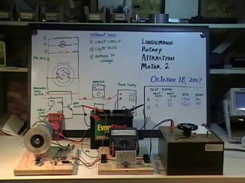
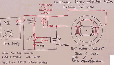
I believe the importance of this motor was that it had NO BACK EMF, could run loads, and recovered much of the electricity that went into it in order to charge a second power source or light a light. It ran on 20 volts at .2 amps, and if it puts out MORE than that, it is NOT demonstrated. It would have blown out that tiny light if it put out MORE. Please show where Peter demonstrates that it does more than RECOVER some of the input energy, which is what he SAYS it does. He specifically says it "recovers some of the input energy." Which he then uses to light the light or charge a battery. It is not a generator that produces power, it is a NO BACK EMF MOTOR.
About Bob's setup:
The two main batteries Bob is using have the negatives connected. Tonight, at my suggestion, he connected the two positives with a diode that allows energy from the charge battery to flow to the source. Putting them in parallel. The batteries have settled out and equalized at a higher voltage than either battery started with. If it is like that in the morning (after running all night) or has gone up, it kinda demonstrates that there is some gain in this system, and that the motor is running for free.
I can almost guarantee that it will have more torque than the attraction motor because the dual rotors mean there are magnets on BOTH ends of the coil, and when you fire the coil as a motor coil, the MAGNETS do most of the work. You get a very strong reaction because of the magnets with VERY LITTLE input. BUT it probably DOES have Back EMF. Haven't tested for that. So choose your poison. We want to build it with "Lenz free" (No back EMF) coils, and then we have the best of both worlds. But it would only be Lenz free at a specific RPM, while Peter's motor has no back EMF at ANY speed.
-
He had it all, got old and passed from the scene all tangled up in red tape with zero funding from the mob.
http://www.free-energy.ws/pdf/teal_newspaper.pdfLeave a comment:
-
Last edited by BroMikey; 04-29-2022, 04:05 AM.Leave a comment:
-
Greetings BroMikey
All research work requires time, effort, dedication and material resources, knowledge and study, experimentation.
Any experimenter who carries out his work in the home workshop requires a lot of merit, he is an explorer, a seeker, and more merit if that experimenter is tenacious and persistent, he will make progress, he may also have setbacks.
Everything that Mr. Dave has shared with us is very relevant, it is part of years of dedication and effort, his contributions are one more link in that tireless search, who else does it, there are few.
Much is demanded of Mr. Dave, much is asked of him, he is claimed, but who gives him support?
He will continue to be a seeker, an experimenter, he faces his challenges, with his advances and setbacks.Leave a comment:
-
That motor has nothing to do with the 3 Battery system. Entirely different circuit. One run battery and charges two other batteries. Plus output from the motor. Has been running for four days now with the primary battery maintaining steady. Just letting it run to see what happens before experimenting to add load to the motor and more motor coils.
Edit: I built this circuit years ago, saw it worked and didn't put out much. Thought it wasn't worth my time. Oh how wrong I was. I told Bob about it, and he built it and saw that you get "a little extra" out of it. I suggested a couple additions based on things I have learned and he implemented them. Now he has something he is very excited about. I am replicating and we are building a much larger version to see if it can be scaled up. If it can, we may come back here and show it. If not, we will let you know it was a dud. The little one is absolutely COP>1, but not by very much. But it is the PRINCIPLES we learn that are important. Which is why we were able to add to this circuit and improve the output. We applied a principle we have learned. The little things can add up.
Edit: According to Bob, motor is still running unloaded 24/7 for seven days not four. And loss of .02 on primary while charging two other batteries in parallel.Last edited by Turion; 04-28-2022, 07:10 PM.Leave a comment:
-
Dave ran out of time and patience a while back so let me fil in the blanks. What Dave meant to say was that he has a bunch of building block circuits he calls 3 battery whatever, that did not do much other than pizz me off because they didn't work and now he is trying to make them all work again to 'save face"Originally posted by alexelectric View Post
Now he claims that the circuit works while connected to a salient pole dual rotor motor. I think that it works too, a little bit, similar to all of his other generators he works on 20% of his time in between more important projects.
The batteries are rising by a few points, nice. I guess that is better than nothing for one lifetime. It's possible. Practical Free Energy? Naw.
Maybe by the weekend?

..Last edited by BroMikey; 04-28-2022, 12:38 AM.Leave a comment:
-
Dave
By the way, Bob French has been running a dual rotor machine for three days now, using the circuit we have been working with. Battery number one, the primary source battery, is holding and the second battery in the circuit, which is the charge battery, has gone up above 14 volts. It also uses induction to capture energy in a secondary coil that is charging a third battery. We are so happy with the performance of the "toy" we built that we have invested in a large prototype that is currently in the machine shop. Its will be a 36 coil machine rather than a three coil machine.
Very well go ahead, it is to take advantage of the induction and recovery, we will be testing, thanks for communicatingLeave a comment:
-
Wow that sounds good Dave. I hope it works out for you without spending to much. I agree there must be a limit on material costs. Not bad progress.Originally posted by Turion View Post
Not saying you need the the nano ribbon cores but you would have to buy 1" tape making blocks then grind off the corners and have them turned on a lathe. That seems like too much trouble.
I think your old iron cores were 1000, the 96 fe-si 3% is 7000 for 60hz and the 97 fe-si 4% is 40,000 crazy swing for a 1% change. fe-cobalt is 10,000 which is replaced by the new nano ribbon but I sure don't know anymore.
The permalloys are far higher and I can see why they give low amps. Sorry. Somebody knows what is best but it ain't me.Last edited by BroMikey; 04-26-2022, 10:41 AM.Leave a comment:
-
I said I was using the best material I COULD FIND AND HAVE TESTED. So there absolutely IS such a thing. It's the material I found and had tested, just like I said. That doesn't mean there aren't other things that are better, but I haven't FOUND anything and HAD IT TESTED.
I know there are dozens of materials with a permeability between 10,000 and 200,000. I never said there weren't. But I don't have the money to test them all. Do YOU? As for the amorphous nanocrystaline material. I have not been able to find a source for cores made of that material that would fit in a standard coil bobbin. We tried. To buy the tape and wind all the coils out of it would be a horrible job, and I have no reason to bother with that. I am building a prototype to prove the things I said are true. Now that I have magnets that are outputting the same as my original magnets, I can get on with that. I don't need "maximum output" to prove my point. All I need is to get the machine up and running. I will leave all those improvements to someone else.
The original machine using iron cores had a specific output. These new coils put out less power for the same number of turns. But I will have 24 magnets on the rotor instead of 6. I have a couple of OTHER options right now, and I will see what works out. I can use a 1" diameter core and make my coil 1 1/4" longer. Or I can leave the core at 3/4 diameter and lengthen it. This might get me enough of an increase in number of turns with the wire closer to the core that the output of the coil is greater. I will find out when the machine is all back together and I can try a couple different coil configurations. Making a longer core with the 3/4 x 3/4 magnets didn't get me any increase, but these new magnets have almost double the pulling power of the ones I was using, so THAT should make a difference.
By the way, Bob French has been running a dual rotor machine for three days now, using the circuit we have been working with. Battery number one, the primary source battery, is holding and the second battery in the circuit, which is the charge battery, has gone up above 14 volts. It also uses induction to capture energy in a secondary coil that is charging a third battery. We are so happy with the performance of the "toy" we built that we have invested in a large prototype that is currently in the machine shop. Its will be a 36 coil machine rather than a three coil machine.
And then I have my setup with no moving parts. I have been working on this for years, but finally figured out some things. I realized the failure of the 3 battery system was not that it didn't charge battery 3. Because it does. And you do recover some of the input energy. It was just that it took far MORE energy to charge battery 3 than actually winds up IN THE BATTERY, (impedance is a killer) and even though you can run a load between the positives, you pull far too much out of batteries one and two to do it. So how do we run between potentials LIKE the 3 battery system without wasting the energy "charging" the 3rd battery, and still recover some of what we put in. When I figured THAT out, it all began to get very, very interesting. How long it will run, I have no idea. But the next few weeks will be loads of fun for me.Leave a comment:
-
what we need is called a medium frequency core material. 1k-2k
The target is power. See this short paper. china calls it amorphous nanocrystalline 1k-107
https://www.academia.edu/44282591/A_...EMENT_ANALYSISLeave a comment:
-
Let me further explain the B/H relationship and the number scale for permeability. Designers spend a portion of their lives learning how to fit everything active into this narrow window.
Chromium, mg copper and many other refined metals of varying proportions are mixed with iron to produce a set permeability number for it.
It needs to be specific, not a one size fits all proposition.

Leave a comment:
-
Okay I thought you said the new system will only put out 1/3 (29%) as much as the iron did.Originally posted by Turion View Post
One more thing you should know. Iron mixed with silicon (electrical grade steel) has a permeability number of 7000 and you had only iron without silicon. Maybe iron has no number because it becomes magnetized. THIs 7000 number is many times used for 60hz.
I am not a core and coil designer and until Thane employed a company (other than your retiring friend) to design and build he was stuck at 1 amp. It wasn't until he used a certain set of specific calculations for the proper curve for that inductance at that frequency that his coils put out 5 times that amount or 5 amps. That's right a carefully designed coil and core operating inside the curve window took a special person to make it happen for Thane. He also pointed out that that company could do a precision winding, not that sloppy backyard stuff looking like a ball of yarn where all your calculations go out the back door.
You my dear Sir like Thane and all the rest are shooting in the dark for the right everything.
But you have another cement project? That's nice. Obsolete you say? Iron is, I know that.
It sounds like you are doing the best you can, good luck with that.Last edited by BroMikey; 04-26-2022, 01:02 AM.Leave a comment:
-
I am not using the "old" permalloy. I am using the best material I could find and have tested. Like I said, if you have a material you have tested, let me know what it is. Just telling me it is "out there" really doesn't help much. If a new core material comes available, I will test it.
The best I got with the magnets I have is 90 volts DC across the load and I forget the amperage. That was with my big rotor. If that is truly only 29% of what I will get with the NEW magnets (which is what the testing showed) it is worth the time and energy to replace the rotor, which is what I am going to do. New magnets will be here Thursday. New rotor the first of next week.
Meanwhile I have two other projects I am working on.Leave a comment:

Leave a comment: