Announcement

Collapse
No announcement yet.

Motor Generators

Collapse
X
 
  • Filter
  • Time
  • Show
Clear All
new posts

  • Motor windings need a sinewave. Using pulsed DC this Chinese scooter controller does this. Memphis you don't have a 3 phase motor with hall. You don't have a DC motor of a conventional design either....

    You must have a target speed. Current is controller like this........

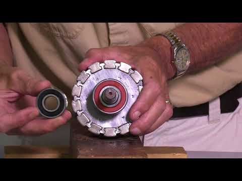
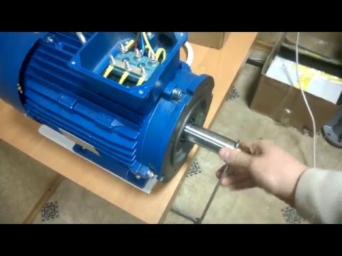
    THE first step for you is to add a small timing wheel to the shaft with tiny magnets. I used an aluminum hub for $5 plus some 1/4 thick plastic disc about 3" DIa.

    your design will never self start, you will need to push it by hand in the direction you desire.

    Last edited by BroMikey; 05-21-2022, 10:35 PM.

    Comment


    • Originally posted by Memphis View Post
      thanks Mikey, very interesting video
      This is the whole enchilada, MOTOR SECRET's

      Comment


      • Dear mikey, the system already works, because the alternator disassembled in the picture gives me the necessary current, and the system runs because there is a 24v brush-less direct current motor mounted on the side on the right that makes the whole rotate . The problem is that the engine absorbs more than the alternator produces (in fact there are batteries connected), so I wanted a circuit that would allow me to power this engine with pulses, and therefore look for the best combination of the length of impulse, to see if it is possible in this way to produce more than what is consumed. Thank you for the video, I was already watching it on youtube, but being long enough and in English, for me, as an Italian, it takes time to understand it, but I'm trying to complete it to understand its explanation, thanks always for your kindness and availability.

        Comment


        • Good job study the video. The video is only 1 piece of this puzzle. The video teaches us how to pulse DC to a motor and recovery 85% of that energy back to a battery. That is a big deal.
          Let me repeat- the video teaches us some history on how to run a motor more efficiently than regular engines can.

          Motors, engines, whatever you want to call it

          I will say it again like this, the video teaches us all to run an electrical motor for 85% cheaper.
          Think of it like this, we know from the books 1hp=750watts and regular motor are only 80% efficient or they loose 20% of 750watts so a 1 hp electrical motor uses 600watts and looses 150watts.

          The video teaches us that the same 1hp motor uses 600watts but does not waste but instead recover 85% of the 600watts which = 510watts returns. So a 1 hp motor only takes 90watts instead of 600watts.

          That is a big deal.

          Now to answer your question you may gain 10% by pulsing the DC but that flywheel should give you 200%

          https://www.amazon.com/RioRand-7-80V...%2C156&sr=8-14
          • Control power: 12V within 300W ; 24V within 400W ; 48V within 450W ; 72V within 500W
          • Duty cycle adjustable range: about 1% -100%
          • PWM frequency: 12KHZ
          Last edited by BroMikey; 05-23-2022, 02:14 AM.

          Comment


          • 555 timer and this $2.50 book. Priceless
            https://www.amazon.com/Ultimate-Begi...s%2C343&sr=8-4
            “Advances are made by answering questions. Discoveries are made by questioning answers.”
            —Bernhard Haisch, Astrophysicist

            Comment


            • Originally posted by BroMikey View Post
              Good job study the video. The video is only 1 piece of this puzzle. The video teaches us how to pulse DC to a motor and recovery 85% of that energy back to a battery. That is a big deal.
              Let me repeat- the video teaches us some history on how to run a motor more efficiently than regular engines can.

              Motors, engines, whatever you want to call it

              I will say it again like this, the video teaches us all to run an electrical motor for 85% cheaper.
              Think of it like this, we know from the books 1hp=750watts and regular motor are only 80% efficient or they loose 20% of 750watts so a 1 hp electrical motor uses 600watts and looses 150watts.

              The video teaches us that the same 1hp motor uses 600watts but does not waste but instead recover 85% of the 600watts which = 510watts returns. So a 1 hp motor only takes 90watts instead of 600watts.

              That is a big deal.

              Now to answer your question you may gain 10% by pulsing the DC but that flywheel should give you 200%
              ...
              Memphis,

              You should not take advice from someone who wrote the post quoted above. It is so wrong. Beware of what BM tells you and what/who he recommends.

              bi

              Comment


              • Originally posted by bistander View Post

                Memphis,

                You should not take advice from someone who wrote the post quoted above. It is so wrong. Beware of what BM tells you and what/who he recommends.

                bi
                I just recommended Peter Lindemann's attraction motor secret which you seem to have a problem understanding. Lindemann is a genius and you? Well never mind we won't go there.

                Comment


                • Originally posted by Turion View Post
                  555 timer and this $2.50 book. Priceless
                  https://www.amazon.com/Ultimate-Begi...s%2C343&sr=8-4
                  I have had one of those 555 timer books from radio shack since the early 70's and I always fall back on it. Great way to start, some of the best circuits are in there plus all of the parts are listed. http://vtda.org/books/Electronics/IC...alterGJung.pdf

                  https://ibiblio.org/kuphaldt/socratic/model/mod_555.pdf

                  This one is real easy

                  https://www.n5dux.com/ham/files/pdf/...20Circuits.pdf


                  .........................
                  Last edited by BroMikey; 05-23-2022, 06:14 AM.

                  Comment


                  • Dear Memphis and to the entire group.

                    I will say it again as I have so many different ways, the people showing excess energy from their motor generator schemes have modified the generator to low cogging. If you don't know Jeff at Missouri Wind and Solar I'll tell you he has been around for years developing a low cogging alternator.

                    The early video shows the original stator core and the updated video also of Jeff shows you how he won the battle. He has no problem sharing it because no one else can make the changes.

                    This new design has a greater efficiency. Low cogging stepper motors used this same approach.


                    Last edited by BroMikey; 05-24-2022, 05:32 AM.

                    Comment


                    • This is how Jeff's rotor looks. The bearings are bigger and the whole thing operates at a lower speed. If you put one on a car for instance, you wouldn't need a 3 or 4 to 1 ratio like a Delco running at 6,000-8,000 rpm's. This one could do well at 1500 rpm's. This is much lower.

                      Last edited by BroMikey; 05-25-2022, 02:57 AM.

                      Comment


                      • Here is the huge version at 48vdc but way more cog free watts.

                        Comment


                        • This guy's company uses regular 3 phase cages. Here is what they do

                          A permanent magnet generator 5,5 kW 1500 rpm 220V It can be used for hydroelectric power. On small speeds, as in video, it produces up to 50 V. The grid tie inverter generates up to 120W. Our company produces generators with power from 500 W to 30 kW, speed 100 to 3000 rpm

                          sales@windkraft.com.ua

                          Totally cogging free, well almost, we know better. Much better than the old way till she starts pullin a large load. It's a little better. You can order the rpm best for your project. Still way under unity.


                          Comment


                          • Generator to motor. Stan M.


                            Comment


                            • IMG-20220526-WA0005[1].jpg IMG-20220526-WA0006[1].jpg IMG-20220526-WA0007[1].jpg to try to explain myself better, why a speed regulator for brushless motors is not good for me, I need to send the current in full pulses, but of adjustable duration, so I tried to put a brush on the flywheel shaft which I connected to the negative of the motor, and I obtained a copper contact that engages about half of the circumference of the shaft, so half a turn the motor has current, and the other half a turn does not. In this way the system starts up as soon as the brush comes into contact with the copper part. The problem that as soon as it starts to turn, takes a minute and the brush burns the copper wire to which it is connected, I have already burned 3, you have to look for another solution, so I was looking for an impulse circuit (so I also avoided the large sparkle of the brush as the current passes) I am putting the photos to you to make you understand.

                              Comment


                              • Hi Bro,

                                You attached a schematic on a DC motor speed controller (Motor PWM) for the 555 timer IC in your post here:
                                http://www.energeticforum.com/forum/...204#post510204

                                Unfortunately, there is an error in the schematic: both 1N4148 diodes are shown with their anodes connected to Pin 7 of the 555. To get a correctly working PWM control, any one of these diodes should be flipped so that a diode cathode and and the other diode's anode be connected to Pin 7. It was not you who made the schematic I believe but it would be good to correct it.

                                Such drawing error can be found also in a LED dimmer circuit here but fortunately attention was drawn to it under the wrong schematic: https://forum.allaboutcircuits.com/t...nerator.93148/ see correct schematic for the LED dimmer here: http://www.555-timer-circuits.com/fo...r.65/#post-406

                                See another correct drawing for instance to control duty cycle and the pulse frequency independently from each other here: https://www.electroschematics.com/pu...ator-with-555/
                                Of course, the pulse output Pin 3 of the 555 should go to the device to be controlled i.e. to a LED or to the base of the motor driver transistor.

                                Gyula
                                Last edited by gyula; 05-27-2022, 02:41 PM.

                                Comment

                                Working...
                                X