 Tweet
Tweet

-
-
You’re right. That will work. Ordered. Will arrive Tuesday. Gracias!�Advances are made by answering questions. Discoveries are made by questioning answers.�
�Bernhard Haisch, AstrophysicistComment
-
That is what I am here for. I see circuits in my dreams. When I first began 40years ago I went to every library I could copied all the big books til I was occasionally stopped for copyright laws. So i would do half and come back tomorrow to do the other half.Originally posted by Turion View Post One thing i can tell you today about posted circuits is most are non functional and outdated by 30 years. All of the regular stuff operating today is censored off the web by China.
Try to fine one of the most commonly used engines today on the web, ICE and you will be forever finding anything that is clear. the web is broken Anyway, enough ranting, it is my pleasure.Comment
-
I didn't get to Sacramento on Saturday to meet my friend, and he didn't get the testing done this morning as planned or bring me the stuff I need. A brand new baby has a way of seeming more important than THIS silly stuff. Not MY brand new baby, his. Anyway, he plans on testing in the morning and then running the stuff up to me, which is a three hour round trip for him. It pays to have friends. Then I will have video of the input and output running a simple two coil system that ANYONE should be able to replicate if they can fashion two coils, a 12 magnet rotor, and spin it with a small electric motor.�Advances are made by answering questions. Discoveries are made by questioning answers.�
�Bernhard Haisch, AstrophysicistComment
-
Congrats to the young man. 12 magnet? 22 magnet? 24 magnet? You got more irons in the fire than carter has liver pills.Originally posted by Turion View Post
Comment
-
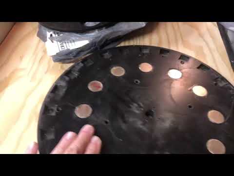
The original machine was 12 magnet N/S rotor. When we built Black Beauty we put 22 magnets in the rotor all N. It didn’t work, so we cut the rotor apart to get all the magnets out and the new machine has a 24 N/S magnet rotor. We are using the 12 magnet machine as a coil tester because we know that whatever results we get, they will be better on the NEW machine when it is all put together. Since it is finally raining here in my part of Northern California and I can’t work on my outside projects, I have time to work on my inside ones.�Advances are made by answering questions. Discoveries are made by questioning answers.�
�Bernhard Haisch, AstrophysicistComment
-
Good idea keep the 12 magnet for testing not the old 5 magnet or 2" six magnet all thread model.Comment
-
All the previous machines except Black Beauty had all-thread for a rotor shaft, and I filed the threads off the ends to fit in bearings. Not exactly a "machined" or "professional" build. But it worked well enough for proof of concept. Lots of corners were cut to save money. Black Beauty was the first really professional build, and even now, I see an issue. Just running black beauty for the time I did, I saw wear on the shaft where the bearings sat. I think the shaft was spinning in the bearing rather than spinning the bearing. I may have to lock the shaft in somehow. The shaft is just cold rolled steel. Over time, that wear will be an issue. I will have to have a hardened steel shaft made. But it will last long enough for testing and demonstrations, and then I can put it on the shelf.
Got all the opposition magnets in yesterday. That is a process. I only have one blood blister from magnet pinches, and it isn't a bad one, so I feel lucky. I hope to get the rest of the machine assembled today. With any luck, I will.
The switch came in yesterday. The high voltage meters are supposed to be in tomorrow. I have pretty much everything except all the coils.
I have had some suggestions for looping this
1. You could use a transformer with a winding ratio of 2.5:1. This would give you an A/C voltage at 120V at whatever frequency the coils run at..You could hook up a 120V bulbs as load in that case.
2. You could rectify the output of the coil with a bridge rectifier and smoothing cap, then use a DC to DC step down converter
3. Convert to DC as in option 2. Then use a solar inverter (those can easily take 300V DC) and they will output 120V A/C at 60Hz. Solar converters typically are 90+% efficient these days. Then you can hook up a bulb or your motor power supply.
What I am looking at right now is taking the output of two coils, which is over 300 volts at 1.5 amps, connecting a bridge rectifier, and then connecting a PH300A280-28, which converts the high voltage DC to lower voltage DC (28 volts, which is almost EXACTLY what we need...adjustable between 11 and 36 volts) at 10 amps. Hopefully the 10 amps is enough to run the generator when all the adjustments for magnetic lock are made. All my fingers and toes are crossed.
https://www.mouser.com/ProductDetail...Q6OuCtnw%3D%3D�Advances are made by answering questions. Discoveries are made by questioning answers.�
�Bernhard Haisch, AstrophysicistComment
-
My friends have been giving me data, and I have been doing the math based on that data. That was my first mistake. And I have been reporting it here. That was my second mistake. As it turns out, I should have verified that the voltages they were giving me were voltages under load rather than open circuit voltages as there is a BIG difference. I did not. I made an assumption. My mistake. Now it is a little late to get voltage under load data on the new coils as I have all of them here, and the coil tester is THERE. And it is a 12 magnet machine while the NEW machine is a 24 magnet machine.
Having said all that, I highly DOUBT that the output of two coils will be enough to power the motor. I won’t know until I get this thing up and running. This may mean that the total output of the machine is less than what I claimed. Then bistander will be right about total output. He will NOT be correct about Lenz free coils OR about magnetic neutralization or even right about what is possible to build, but there is a chance he is correct about TOTAL output for this specific machine being less than the 1800-2000 watts I claimed.
It will still probably be COP>6 or more but not as much as I thought. Those iron cores just put out way more power. My original measurements of those coils WAS under load, but they just get too hot. So my search for a core material goes on. The old machine with those iron core coils did exactly what I said it would do. This new machine with the new core material will probably not. Not enough output from these coils. But still OU.Last edited by Turion; 10-22-2021, 09:39 PM.�Advances are made by answering questions. Discoveries are made by questioning answers.�
�Bernhard Haisch, AstrophysicistComment
-
The tdk/lambda is awesome, you will need a heat sink and a fan, check the bolt pattern heat sink pasteOriginally posted by Turion View Post
On the transformer idea?whatever freq is going into it also comes out same freq AC. A transformer design would be tiny, then rectify send to a cheap $10 controller
watch those phalanges Last edited by BroMikey; 10-22-2021, 09:36 PM.
Comment
-
the olden days
Comment
-
Comment
-
cop 3 for 10 minutes better than everybody else who has nothing
 Last edited by BroMikey; 10-23-2021, 08:00 AM.
Comment
-
So here are the facts. The old clunker machine with iron core coils was able to put out between 1800-2000 watts. The input was 36 volts at 12 amps and with adjustment we could get it down to 7 amps, but it wouldn’t STAY adjusted. Too much play in critical areas. The mechanical issues were addressed, and my hope was that this NEW machine with twice as many magnets on the rotor would be more powerful. Perhaps TWICE as powerful.
And it may well be, but I am not using the same coils because they heat up too quickly and melt the coating off the wires after about 30 minutes of constant running.
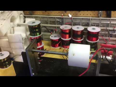
So I have been busy doing the thing I like least in the world, which is winding coils while my partners in Sacramento cut, coated, and epoxied in the core materials. They also tested coil pair for output on the old clunker and shared the data with me which I posted here.
They would send me videos of coil tests and kept track of data so we could make a decision on what core material to use. One of those videos is what a few people here saw. There is a problem with the testing that was done. The numbers are open circuit voltage numbers, not voltage under load. This wasn’t clear until watching the videos a few times and I called to confirm. By the time I realized the issue, I had already picked up all the GOOD coils and brought them home. So the voltage under load test he did yesterday was with a pair of mismatched coils and ones that produced LESS output than the wiring configuration we are using on the GOOD coils. BUT, the test shows that these new coils don’t put out NEAR the voltage of the iron core coils. Only about 55-60%.
My hope is that the GOOD coils put out enough more than the mismatched coils that with a 24 magnet rotor I will be right back up to the original 1800-2000 output of the original generator. But I am very aware it could be less.
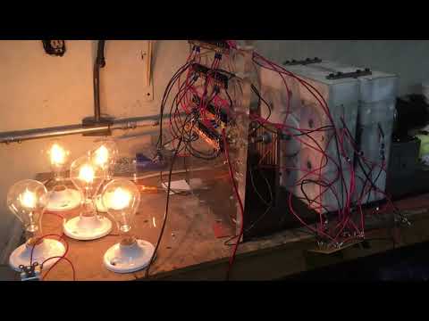
But I want to be clear about a few things. The measurements I took on the original coils were ALWAYS under load, so those numbers are accurate. I first time I fired up a coil pair the bulb didn’t light up and it took me a bit to figure out I had blown it. And a coil pair blew two 100 watt bulbs in series. It lit 3 to brighter than when connected to wall voltage and increasing the RPM would blow the bulb, so I am very aware of the voltage and amps I was getting because I used an oscilloscope as well as several different meters.
But as to total output of this machine with this new core material, it’s an unknown until I see it run on the bench. And if I want to win the bet with bistander I might have to put all the old coils back in it. I could. But I am curious to see what this machine will output with these new coils and will go from there. This motor could turn a second or even a third rotor. That would be a much bigger machine, so I will probably leave that to someone else.
oh, the mismatched coils under load were outputting 77 volts at 1.3 amps. Not even close to the 120-130 volts at 1.5 amps the iron core pair put out. But that’s with a 12 magnet rotor. I don’t know what MATCHED coils will do on a 24 magnet rotor yet. So it may be back to testing core material. We still have a couple we didn’t test, but I wound the extra coils already.�Advances are made by answering questions. Discoveries are made by questioning answers.�
�Bernhard Haisch, AstrophysicistComment
-
Data
300 watt bulb yields 77 volts at 1.3 amps
100 watt bulb yields 180 volts at .9 amps
Tomorrow they hope to run a DC motor off rectified voltage and see what happens. And then put the motor under load.Last edited by Turion; 10-24-2021, 12:06 AM.�Advances are made by answering questions. Discoveries are made by questioning answers.�
�Bernhard Haisch, AstrophysicistComment
Comment