 Tweet
Tweet
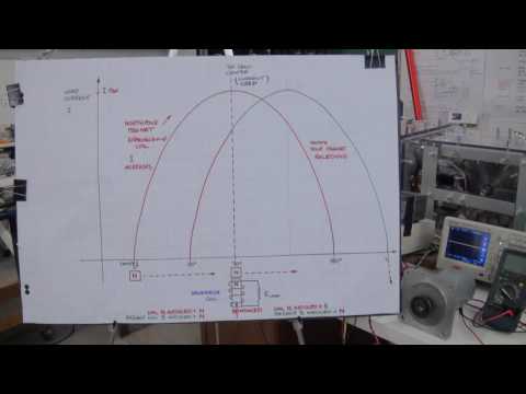
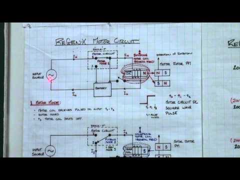
Here is Alex patent in full showing how reduced size 10,000 rpm 3 phase
generators can still get 90 percent efficiencies.
https://patents.google.com/patent/US9444294B2/en
generators can still get 90 percent efficiencies.
https://patents.google.com/patent/US9444294B2/en


 Come on Dave give me a break to think all this time.........
Comment