Announcement

Collapse
No announcement yet.

Motor Generators

Collapse
X
 
  • Filter
  • Time
  • Show
Clear All
new posts

  • #76
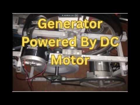
    Motor Generator Looping successfully.


    Last edited by BroMikey; 01-21-2020, 09:31 AM.

    Comment


    • #77
      Originally posted by BroMikey View Post
      Here again is proof or spoof? of an electric magnet
      motor generator taking up very little space and
      yet runs a 1000 watt load.

      Naturally we all know it just can't be done, right?


      Breakdown FOR THE NAYSAYERS


      [VIDEO]FFULC3zaqPY&nohtml5=False[/VIDEO]
      This is the final product, in the generator with looped bifilar coils.
      It is based on this design and that's clip where they presented it.

      [VIDEO]watch?v=Xb6_gy7j3k0[/VIDEO]
      https://www.youtube.com/watch?v=Xb6_gy7j3k0

      Comment


      • #78
        Thank you Rakarskiy

        Please continue to inspire and update me on this thread
        for motor generator with no outside energy sources.

        Also transformer energy static generator.

        This is a very large break thru.

        Exciting results. I have seen this video before and didn't
        understand it.


        Last edited by BroMikey; 01-21-2020, 09:31 AM.

        Comment


        • #79
          [VIDEO]watch?v=J14tzHXX4y4[/VIDEO]
          [VIDEO]watch?v=1n2KuK_YD5U[/VIDEO]

          Comment


          • #80
            Originally posted by Rakarskiy View Post
            [VIDEO]watch?v=J14tzHXX4y4[/VIDEO]
            [VIDEO]watch?v=1n2KuK_YD5U[/VIDEO]
            WOW!! I didn't see that, keep posting all good video's
            like these right here on this thread.

            (Odessa, Ukraine) are very smart researchers.

            Last edited by BroMikey; 04-20-2016, 05:55 AM.

            Comment


            • #81
              Here is how everyone starts.


              Last edited by BroMikey; 01-21-2020, 09:32 AM.

              Comment


              • #82
                Motor-Generator Vega (Odessa, Ukraine).
                Developed and produced in small batches motor-generator VEGA, the company DP VERANO in Odessa.
                At the heart of the three-phase generator with permanent magnet excitation. By kotormu propeller instead of vertical type, made with the recovery pulse motor coils.
                [VIDEO]watch?v=XNWO3Dk4La0[/VIDEO]
                [VIDEO]watch?v=MgR9i3oLrfQ[/VIDEO]
                [VIDEO]watch?v=z8faG9YM7EE[/VIDEO]
                feature of the device is that the generator produces 380 volts three-phase. With three-phase generator connected to a three-phase charger that converts 380V to 24V to charge the batteries with removable oganicheniem power. The generator also has features the combined use of to excite the neodymium and ferrite magnets.
                In the Russian-speaking community of seekers of free energy is still tense debate fake it or not.
                Показан перевод для запроса Изделие и сегодня выставлено на продажу
                Искать вместо этого перевод для Изделие и сегодня выставленно на продажу
                The product and now put up for sale
                403 Forbidden
                The only question is the price and the main thing that responded (not all meet)

                Comment


                • #83
                  This motor generator it is a prototype, but they have a bigger one working, the concept is original.

                  https://www.youtube.com/watch?v=R1cudmCavoY
                  Last edited by fer123; 04-18-2016, 12:14 PM.

                  Comment


                  • #84
                    This is generator without breaking force.

                    generador sin tracciones - YouTube

                    Comment


                    • #85

                      Comment


                      • #86
                        This is good information for experimentation.

                        Excellent.


                        Originally posted by Rakarskiy View Post

                        Comment


                        • #87
                          Question on coil layouts

                          Hi Serge,

                          Thanks for showing the details. My question would be on the coils layout: you show two winding techniques, one seems to be a bifilar, multilayer and the other shows one coil on one half (and multilayer) and the other coil is shown on the other half part of the bobbin (also multilayer).
                          Is this correct as I understand the layouts from your drawing?
                          Do the two winding layouts give equally good results? Or the bifilar winding may be better?

                          Thanks, Gyula

                          Comment


                          • #88
                            I'll try to explain. For example: Normal bifilyar is wound with two wires, all traditionally pay attention to it. But there are still options. Naprmer coil with two windings, one of which is wound counter-clockwise, and the second while moving clockwise.
                            If we consider a spiral vortex flow EMF from penetrating magnetic flux, they are opposite with respect to coil poles, and have a common direction of rotation (right-hand rule). It turns out that the data reception, we remove the counter induced EMF.
                            The figure below clearly shows, this winding to the secondary winding of the transformer, only the connection - serial.
                            In the case of M-G data Sbodyan are connected by parallel windings, such that represent common circuit.

                            Comment


                            • #89
                              Hi Serge,

                              Thanks for your answer, but I realized in the meantime that I probably misunderstood the coil layout and I thought coil layout nr 1 (I encircled in red on the left) showed a bifilar winding. I realised it may not be a bifilar winding but the red coil labelled as "a" is wound counterclockwise and the blue coil labelled as "b" above it is wound clockwise direction. (So this is not bifilar winding if we define bifilar as using two wires and we wind the two wires together in the same direction as normally for bifilar coils.)

                              I also drew a black arrow from one of the coils in the picture to the drawing nr 1 to show that its winding layout (and all the 8 coil winding layouts) corresponds to your coil layout nr 1, is this a correct assumption?

                              In your other coil layout nr 2 on the right side you show the two coils are not layered above each other but positioned next to each other. To make such coils you need to divide the bobbin into two sections and in one section on the left the red winding would go counterclockwise and in the other section on the right side the blue winding would go clockwise direction. This 2nd winding technics is not applied in the prototype setup shown in the picture, right? (because I cannot see the two sections on the bobbins, that is.)

                              So these are what I meant with my question, sorry for my mistake to confuse normal bifilar winding with the clockwise and counterclockwise windings.

                              So do I understand the coil embodiments correctly now? or I still confuse something?

                              Many thanks for your time and answers.

                              Greetings,
                              Gyula
                              Attached Files

                              Comment


                              • #90
                                Originally posted by Rakarskiy View Post
                                I'll try to explain. For example: Normal bifilyar is wound with two wires, all traditionally pay attention to it. But there are still options. Naprmer coil with two windings, one of which is wound counter-clockwise, and the second while moving clockwise.
                                If we consider a spiral vortex flow EMF from penetrating magnetic flux, they are opposite with respect to coil poles, and have a common direction of rotation (right-hand rule). It turns out that the data reception, we remove the counter induced EMF.
                                The figure below clearly shows, this winding to the secondary winding of the transformer, only the connection - serial.
                                In the case of M-G data Sbodyan are connected by parallel windings, such that represent common circuit.

                                Thank you for your instruction, now I have something
                                to ponder today. Yes I heard you about
                                fields with normally wound coils (same direction bifilars)
                                how the fields offer the EMF so you wind one CCW and
                                one CW.

                                So I think you are saying reception from one coil to the other
                                is better and maybe without the EMF.

                                Anyway you have my attention. Still thinking about this one.

                                Last edited by BroMikey; 05-13-2016, 07:45 PM.

                                Comment

                                Working...
                                X