If this is your first visit, be sure to
check out the FAQ by clicking the
link above. You may have to register
before you can post: click the register link above to proceed. To start viewing messages,
select the forum that you want to visit from the selection below.
VOL- XIV~ NO- 1--JULY 0. 1989-J 9 THE -ELECTRICAL VVORLD. The Tesla Self-Starting Alternating Motor System. As is well known, certain forms of alternating current machines have the property, when connected in circuit with an alternating current generator, of running as a motor in synchronism therewith; but, while the alternat- ing current will run the motor after it has attained a rate of speed synchronous with that of the generator, it will not start it; hence, where these �€œ x-ynchronizing mo- tors,�€� as they are termed, have been run, some means have been employed to bring the motors up to synchronism with the generator before the alternating current of the generator is applied to drive them.
In some instances mechanical appliances have been utilized for this purpose. In others, special forms of motor have been constructed. With the object of eiiecting the starting of the alter- nating motor and bringing it to synchronism without ex- ternal aid, Mr. Nikola Tesla has devised a. simple system in which he employs an earth return during the period of starting only. For this purpose he constructs a generator with two coils or sets of coils and a motor with corres- ponding energizing coils or sets of coils. By means ot two linewires, one terminal _ of each generator coil is connected to one terminal of its corresponding motor-coil while the opposite terminals of the generator- coils are joined together, and likewise those of the motor.
To start the motor an electrical connection is temporarily established between the points of connection between the coils in the generator and those in the motor, so that the system becomes an ordinary double-circuit system. When by this plan of connection the motor has attained the desired speed, the earth connection is severed, by which means the system becomes an ordinary single circuit synchronizing system. The accompanying diagram shows the manner in which this is accomplished, G representing an ordinary alternating current generator having four held poles A; magnetized by a continuous current, and an armature wound with two coils C connected together in series. M represents an alternating-current motor with, say, four poles D, the coils on which are connected in pairs and the pairs connected in series. The motor- armature should have polar projections and closed coils E. Froin the common joint or union between the two coils of both the generator and motor an earth-connection F is established, while the terminals or ends of the coils which they form are connected to the line-conductors. Assuming that the motor is a. synchronizing motor, or one that has the capability of running in synchronism with the generators, but not of starting, it may he started by the above~described plan by closing the ground-com nection from both generator and motor. The system thus becomes one with a two-circuit generator and motor, the ground forming a common return for the currents in the two line wires. When by this arrangement of circuits the motor is brought to speed, the ground connection is broken between the generatornr motor, or both, and ground switches K K being employed for this purpose. The motor then runs as a synchronizing motor. 1: -ff" H <�€™§\\ vi ii " hi ll] ` - ~ �€˜Joni L54 ta g; iii #1 _ I P _ , TESLA SELF-STARTING ALTERNATINQ MOTOR
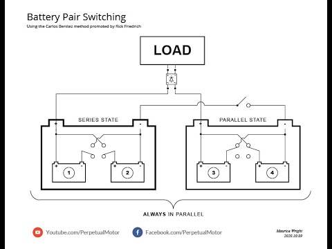
Continuing the Tesla Switch style of operation, it is possible to get the same effect as the Tesla Switch circuit, using only three batteries (or three capacitors). Discussed almost a century ago by Carlos Benitez in his patents, and more recently described by John Bedini, just three batteries can be used if more complicated circuit switching is used. Carlos points out that there has to be an energy loss due to wires heating up and batteries not being 100% efficient. He overcomes these problems with some very clever circuitry which is covered in the following section. However, it is not at all certain that this is actually the case as experimentation indicates that it is possible for this kind of battery switching to maintain the battery charge levels far beyond the expected.
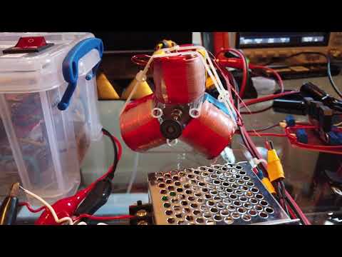
Some YOUTUBE stuff out there but not specifically like the patent. I didn't know Carlos said that from your posted quote. Here we see coils as resistors and batteries are caps.
Then the arcing brush discharge switching most think is the same as a simple set of relay contacts. nope
The way he portrays his patent, this image using coils and caps runs like a clock and never goes down even tho he is draining power off.
EVGRAY used carbon or graphite arcing discharges to such in cold lectric just like Tesla's spark gap coil on cars of old.
“Splitting the Positive” and this is directly related to the three-battery system in principle.The well-known “Tesla Switch”,which came from Ronald Brandt has nothing to do with Tesla,but is related to what Lindemann is presenting and it operates a load between two negatives._I presented on a cold electricity circuit a couple years ago and it also operates a load between two negatives.These are all overunity circuits,which have one thing in common,they all appear to have their roots in one man’s work and that is the Self-Recharging Battery Supply of Carlos F. Benitez.
Remember what Benitez said:
Quoting Benitez's patent, "Obviously the current furnished by the discharge of battery 1 & 2 alone, would produce a SMALLER CHARGE in batteries 3 & 4, if some energy were not added to the normal output of said battery 1 & 2. With this object in view any of the known methods for the generation of high frequency currents, as well as those described in the aforementioned English patents, can be employed in conjunction with said batteries, in order to provide that complimentary energy, and in this manner it is always possible to charge and discharge alternately each battery from one to the other, maintaining a constant storage of electricity and producing furthermore and excess of electrical energy."
5 years ago What is probably misunderstood is that the coils are shown as what we draw today as a resistor. This was done in the earlier days to represent the coil being shown as a high resistance winding. This is also shown when wire wound resistors are being drawn. it's difficult to tell, however it makes sense to know the inductor coils are used for 2 purposes, as a resistor, and they can be used as an inductor. This is one of the best ways to allow cold electricity to flow, through the higher resistances, more energy flows, but, to be used for anything worth operating anything, the energy needs to be stored in capacitors to convert the energy back to conventional energy, and it usually amplifies the amount of energy used in a circuit to create the cold electricity in the first place. For instance, if we use 250 milliamps to make oscillations in an effort to generate cold electricity, we could drive this energy into a single coil as a primary, then byu resonant coupling at high frequency, transfer this energy to a split coil wound int he same direction, rectify both coils and wire them past the rectifiers in parallel to amplify the output by adding the same amount of voltage and amperage to a load, or to a step down, by adding a spark gap between the step up and step down like Don Smith did.
In one of his videos or presentations Peter Lindemann talks about the good old days. When your car battery on your four speed vehicle was dead, you pushed it to get it rolling down a hill, jumped in to pop the clutch, and away you went. Once you got it running your alternator would charge the battery right up. Why? Because it provided the battery with TWO things. The First was constant current and the second was a pulse.
I know you are working with a four battery switch, but for the sake of simplicity let’s take a look at the 3 battery system. When you run the Matt motor between the positives the commutator breaks the contact between the positives of the two batteries and you get a high voltage spike from the motor coil collapse that moves in the direction of least resistance (toward the 12 volt battery rather than the two in series for 24 volts) but you do NOT get constant current because the commutator broke that connection. If you run the boost module between the positives you get constant current but NO spike.
To take FULL advantage of what is possible, run the boost module between the positives on the three battery system with the output set to 26 volts. Then run the Matt motor between the output of the boost module and battery 3 positive. Running the boost between the positives gives you constant current and running the Matt motor gives you the spike.
This is the best results you are going to get using that setup to charge batteries. Again, more or larger batteries in the 3rd position means less impedance, and a cap across battery 3 doesn’t hurt either.
This just gets you the extended run times you are looking for. Without a source of POWER generation (like the motor turning a Lenz free generator) that’s about all you will get out of the 3 battery system.
Matt got the Benitez stuff to work. Absolutely and completely. He is probably your best bet on moving forward with the 4 battery switch. If he will talk to you.
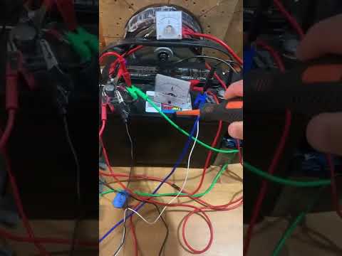
Yes, I did get some good running time from the just 4 battery Carlos Benitez setup. I read somewhere that Matthew said it's cheaper to purchase solar and batteries than buying many batteries to use for the 4 battery switching setup. I tried the Tesla 4 battery switch circuit setup with high hertz switching using relays. Got very mixed results but the relays were very unreliable and a pain to deal with. The Arduino will work with high switching hertz. But the relays, at least the ones I used, can't switch on//off that fast.
Like Matthew said it's best to use mechanical switching for the Tesla setup. I'm not able to build a mechanical switch in my shop or the electronic knowledge to use electronic switching.
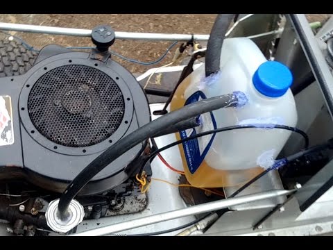
Using the Carlos Setup setup, I used a solar inverter on the 12 volt side (parallel batteries) while powering a 24 volt charger to charge the 24 volt batts in series. Meanwhile had my shop powered by the inverter at same time. After running for so many hours I'd reverse the large DPDT switches and do the same with batteries switching places.
I accept any help or advice on this subject. Not poor mouthing, but I'm now retired and have limited resources.
Thanks Dave I may try the 3BGS again if the Matt motor doesn't heat up again.
In one of his videos or presentations Peter Lindemann talks about the good old days. When your car battery on your four speed vehicle was dead, you pushed it to get it rolling down a hill, jumped in to pop the clutch, and away you went. Once you got it running your alternator would charge the battery right up. Why? Because it provided the battery with TWO things. The First was constant current and the second was a pulse.
I know you are working with a four battery switch, but for the sake of simplicity let’s take a look at the 3 battery system. When you run the Matt motor between the positives the commutator breaks the contact between the positives of the two batteries and you get a high voltage spike from the motor coil collapse that moves in the direction of least resistance (toward the 12 volt battery rather than the two in series for 24 volts) but you do NOT get constant current because the commutator broke that connection. If you run the boost module between the positives you get constant current but NO spike.
To take FULL advantage of what is possible, run the boost module between the positives on the three battery system with the output set to 26 volts. Then run the Matt motor between the output of the boost module and battery 3 positive. Running the boost between the positives gives you constant current and running the Matt motor gives you the spike.
This is the best results you are going to get using that setup to charge batteries. Again, more or larger batteries in the 3rd position means less impedance, and a cap across battery 3 doesn’t hurt either.
This just gets you the extended run times you are looking for. Without a source of POWER generation (like the motor turning a Lenz free generator) that’s about all you will get out of the 3 battery system.
Matt got the Benitez stuff to work. Absolutely and completely. He is probably your best bet on moving forward with the 4 battery switch. If he will talk to you.


 keep at it


Leave a comment: