Announcement

Collapse
No announcement yet.

Magnet motor revelation

Collapse
X
 
  • Filter
  • Time
  • Show
Clear All
new posts

  • Ufopolitics
    replied
    Originally posted by lorinrandone
    Hola Ufo
    you are right, but Mad Mack said <play> with poles with angles .... is it?
    What I've done has been to balance the rotor. I do not know the angle
    Cristian,

    Tu lo estás haciendo bien, solo que en vez de rotar 30 grados los imanes del rotor...tú angulaste a los estatores (imanes estáticos). El problema está en que cuando adiciones las "Rampas" de aceleración puede que no te dé los resultados esperados.

    Los estatores deben estar orientados directamente al centro de rotacion.
    Los imanes de el rotor deben ser los que tengan angulación, alrededor de los 30º.

    Pero me gusta que no tienes "casi" nada de restricción magnética.


    Saludos


    Ufopolitics
    Last edited by Ufopolitics; 09-05-2015, 07:43 PM.

    Leave a comment:


  • Ufopolitics
    replied
    Thanks...

    Originally posted by tachyoncatcher View Post
    Ufo,
    I went to my workbench and tried to confirm what I read in that book. My tests support what you said and not the book. Wow! A good lesson in confirming what you read. I will remove the content of post 130, but leave the post as a place marker for reference. Thanks for your patience and the lesson.
    Respectfully,
    Randy
    Thanks to you for checking that simple experiment out by yourself...plus coming back to post what am saying is correct and not what the old establishment is repeating-teaching for almost two centuries.

    Thanks for deleting your post 130, and I will leave mine as the reference.


    Regards


    Ufopolitics

    Leave a comment:


  • tachyoncatcher
    replied
    You are correct!

    Originally posted by Ufopolitics View Post
    Randy,

    First, the images and text I have done on that post are all based on MadMack descriptions which are all Quoted in between each graphic and verifiable with the arrow link at each quote start. (it will take you to the original post)

    Sorry, but if you read my previous post you will realize what am saying...

    (1) Just get a Magnet and approach its North to another iron bar of about same mass...and read it out...check it out...by getting it near it...or even making contact with it...you will then notice the whole iron bar becomes a North Pole in both scenarios.

    This is material from a Book I am writing about Magnetism...where I have done countless testing, screening and not with ferrous powder, which is complete BS...but with Viewing Film, Ferrocell Lenses...and CRT Imaging.

    I just do not want to mess up this thread by starting an argument based on all that...or bringing up proof pictures and testing etc,etc

    Just perform those very simple tests I've mentioned above (1) and you will convince yourself about it.

    Bottom line is that I agree with the way Mack describes the way this Induction takes place...except for minor details.


    Take care


    Ufopolitics
    Ufo,
    I went to my workbench and tried to confirm what I read in that book. My tests support what you said and not the book. Wow! A good lesson in confirming what you read. I will remove the content of post 130, but leave the post as a place marker for reference. Thanks for your patience and the lesson.
    Respectfully,
    Randy

    Leave a comment:


  • Ufopolitics
    replied
    Originally posted by lorinrandone
    Another variant of magnets. https://www.youtube.com/watch?v=Sbr5...ature=youtu.be I removed my Adams motor, and if all was ready ..... Behold
    regards. cristian alba
    Excellent work Cristian!

    And I believe you don't even have Ramps mounted yet...and only two stators...

    You only have changed the 30º angle deviation to the stators instead of rotors...but who cares as long as it works right?

    Great to see it running!


    Ufopolitics

    Leave a comment:


  • Ufopolitics
    replied
    The way I see it...

    Hello again,

    [IMG][/IMG]

    Above is the minor difference I see on Ramp Induction from MadMack's description...no South Pole at right end...but North Pole "extension" from Rotor Magnet, and of course, as rotor moves this N extension will be less or more area over the iron ramp, which actually attracts and not repulse.

    Both of this two Influences on the Ramp generate attraction from Rotor Magnet towards the strongest South Center Stator area. Therefore, both are positive to rotation, except that IF we do NOT bend the way Mack describes...then having more iron mass passed the North Rotor Pole center line (Bisector)...then we WILL have a negative pull, or a tendency to KEEP Rotor at that generated Center North area of Ramp.

    Again, the design is awesome!...and I do agree with it.

    By the way, I just got eight N52 Cubes of 1"X1"X1/2"...They could pull easy 40 pounds...very heavy and hard to manipulate and dangerous...but it is the way Mack recommended on his first post...N52's Neos.


    Regards


    Ufopolitics

    Leave a comment:


  • Ufopolitics
    replied
    Originally posted by tachyoncatcher View Post
    Hi Ufo and others,
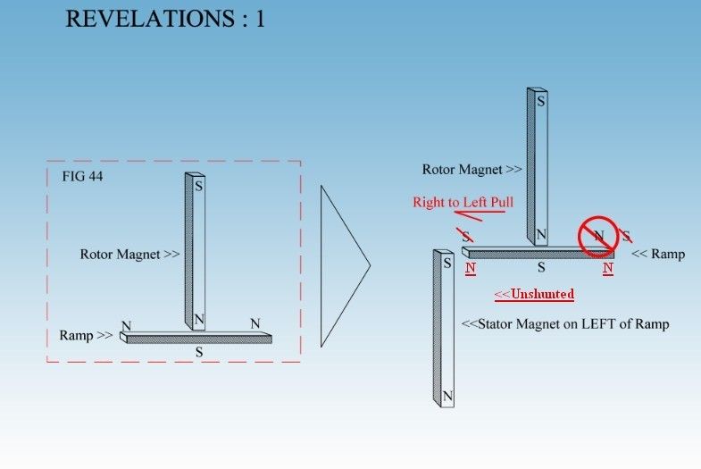
    I believe having a correct understanding of Magnetic Induction is the only way to a working device. Ufo, I have added my edits to your drawing with red underlined text, which I believe are the true polarities of the ramp as drawn. I hope you are ok with that. We have two separate forces at work on the ramp. Magnetic Polarity through induction and Magnetic Attraction to ferrous material. Unless shunted the stator's south pole will induce a North pole to the ramp. The moving rotor will induce a moving south pole. That south pole, in the ramp, will follow the rotor magnet until the induced pole of the stator magnet stops its movement. Then you will have a repelling North pole on the ramp just before the attracting South stator magnet. This is what Mack warned us about. Let's not forget about the Attraction force. This is always present regardless of poles. Yes, like poles repel, but have you ever pushed repelling poles together, only to find that last few thousands of an inch go together easily? Magnetic Attraction at work. (my opinion)

    Unlike in the drawing, it is my belief the leading ramp to the attracting stator magnet should be induced by the opposite pole on the attracting stator magnet. With a shunt between the ramp and the South, attracting pole. This way the ramp, that is facing the rotor's north is always an induced south, with the north of the ramp getting pushed to the back side of the stator magnet.

    Randy

    Randy,

    First, the images and text I have done on that post are all based on MadMack descriptions which are all Quoted in between each graphic and verifiable with the arrow link at each quote start. (it will take you to the original post)

    Sorry, but if you read my previous post you will realize what am saying...

    (1) Just get a Magnet and approach its North to another iron bar of about same mass...and read it out...check it out...by getting it near it...or even making contact with it...you will then notice the whole iron bar becomes a North Pole in both scenarios.

    This is material from a Book I am writing about Magnetism...where I have done countless testing, screening and not with ferrous powder, which is complete BS...but with Viewing Film, Ferrocell Lenses...and CRT Imaging.

    I just do not want to mess up this thread by starting an argument based on all that...or bringing up proof pictures and testing etc,etc

    Just perform those very simple tests I've mentioned above (1) and you will convince yourself about it.

    Bottom line is that I agree with the way Mack describes the way this Induction takes place...except for minor details.


    Take care


    Ufopolitics
    Last edited by Ufopolitics; 09-05-2015, 05:54 PM.

    Leave a comment:


  • Ufopolitics
    replied
    My agreements and discrepancies ...

    Ok, again, about the above post and the book cited here...which is the old classic magnetism rules we have been taught in all this years...

    I am really sorry, but I have to disagree with the magnetic influences on iron from a magnet, and when I say "influence" let's just figure a Non Contact but just to approach with narrow gaps...however, even when contacting this old theories are all wrong...sorry again for bringing this up...but anyone could check this out in a very simple testing:

    Whenever we approach the North Pole from a Magnet to an Iron Bar end, that iron bar end and actually the WHOLE Bar becomes a North...and NOT a South/North sequence!

    This could be tested with a simple Compass...all the way to a CRT Imaging...or Viewing Film screening.

    Now, that North the iron bar becomes by Influence does NOT becomes a 'separate' North Pole...therefore, it does not Repulses the magnet's North Pole, it is just an "extension", which the Main Magnet Polarized end tries to attract to its Center plane.

    However, all of the explanation that I have quoted in my previous post by MadMack makes sense up to a certain point...please allow me to put it on graphic first to then explain:

    [IMG][/IMG]

    Above is all the previous cited text and graphics applied to a Rotary Motor...

    I do agree that the South Stator Pole "Induces" a South "extension" at the Ramp closest end.

    I do agree that the North Rotor Pole Induces a North "extension" to the other side of ramp. But remember that this extension would NOT cause a repulsion...but an attraction towards Iron Mass.

    I do agree that the ramp will cause an acceleration from rotor magnet North Pole towards the "strongest South" .

    But, I do not see anywhere there could be a South Pole at the right end of the Ramp...I see that Half of that Ramp would be an extension of the North Rotor Pole while the other end would become another extension from the Stator Pole.

    I do see that bending away the ramp on the right side will reduce reverse pull or negative counter forces to rotation...simply because we are reducing the ramp iron mass to be attracted by Rotor North Pole...then "shunting it" or deviating it towards the right direction...

    So, concluding... in the end the whole concept makes sense (including the small disagreement I have here) and will just reinforce the design explanation disclosed by MadMack...


    Regards


    Ufopolitics

    Leave a comment:


  • tachyoncatcher
    replied
    Magnetic Induction is Key

    Removed for inaccuracies.

    Randy
    Last edited by tachyoncatcher; 09-05-2015, 06:42 PM. Reason: My mistake.

    Leave a comment:


  • Ufopolitics
    replied
    Illustrating Revelations...per MadMack Posts

    Hello to all,

    I have gone -again- over this great disclosure and explanation...and trying to illustrate MadMack examples as his descriptions, I have underlined the essential parts:

    Yes, reading in between lines...

    Originally posted by MadMack View Post

    Page 66, fig. 44.

    [IMG][/IMG]

    That is essentially a rotor magnet and an acceleration ramp. The vertical bar magnet is the rotor magnet and the horizontal iron bar is the ramp. See the magnetic poles induced into the ramp by the rotor magnet? There are 3 north poles. Obviously the north poles at both ends of the ramp, which are created by the rotor magnet, will try to keep the north pole rotor magnet from moving past the middle. We can add some rake by angling the ramp but that will only alter the balance point a little and the rotor magnet will still try to remain over the ramp at the balanced point. Result: a non working motor.
    Originally posted by MadMack View Post
    So we fix this by putting a south pole stator magnet under the left side of the iron bar in fig. 44. If the stator magnet is not over the ramp, the ramp will have a south pole on the left and a north pole on the right. Now there is a strong south pole that will pull a north pole rotor magnet toward it, right to left across the ramp. The closer the rotor magnet gets to the stator magnet the stronger the pull. Right?

    [IMG][/IMG]

    Yes, but what is going on now at the right end of the ramp? There is a north pole at the end of it right? So that should push against the rotor magnet and help things even more. Right?

    Well, no. What is happening now is the rotor magnet is inducing a south pole into the ramp at the right end which will try to pull the rotor backwards. We just can't win it seems. Even though the rotor will now pull toward the south stator magnet at the left, that pull is being robbed of its strength by the affects of magnetic induction in the ramp, the induced south pole at the right. The degree of loss drops as distance between the rotor magnet and south pole stator magnet decreases, and distance between the rotor magnet and the south pole at the right end of the ramp increases.

    So, what could be done to reduce this unwanted loss? The induction can't be done away with. We are restricted to the single rotor and stator magnet for magnetic sources, and we have the ramp itself. No other magnets or mechanical mechanisms are available. The acceleration ramp will eventually have another magnet a little ways past the right end of it and we don't want to get to close to that with the ramp, so what is left to do that will reduce the loss?
    And...The Solution:

    Originally posted by MadMack View Post

    [IMG][/IMG]

    The answer should be easy if you understand what is going on here. The ramp does not have to be a straight piece of iron. We could add some length to the right end of the ramp and bend this extra length down and away from the rotor. This would place the induced south pole farther away from the rotor magnet and reduce it's affect.

    That's all for now. I wanted to write more but I'm out of time.

    The point of this post was to illustrate why you need to dissect the motor into its smallest components, understand what is happening during operation and take every action and reaction into account. It's the small things make the difference.
    So concluding, the ramps should have the affecting INDUCED poles to rotation curved/bent down and AWAY from Rotor Magnet...in order to make prevail the ones we need for rotation closer to rotor magnet. One thing is not seen is what kind of TRUE induction BOTH Magnets (Rotor and Stator) would be affecting the Iron Ramp?...Only testing ourselves would give Us results.

    Plus, this was about the Attraction side end...We still need to look into the Repulsion arrangement...

    One thing is clear...and that is to make sure we verify what polarity the iron ramps ENDS is INDUCED when approached by Rotor Magnets...or what happens under the influence from North or South Stator Magnets.

    The basic idea of making the Two Pole Rotor/Stators is to First, have them balanced to a perfect ZERO MAGNETIC EFFECT where NO COGGING is observed...

    Then to test with Ramps in different positioning and bending angles...to obtain the positive result where rotor magnets PASS THEIR CENTER MAX POINTS.

    The other thing to consider is the Air Gap...weaker magnets (Ceramic) will need shorter gaps...while an N52 could afford wider gaps.

    IMO A Two Pole arrangement is just a MODULE of this set up...after we achieve this Module performing the way is supposed to work, by passing the Stator Magnets Center Line and gaining enough inertia impulse to reach the REQUIRED ANGLE to start interaction with the NEXT MODULE...then the whole thing would be just to "Copy and Paste"

    That is what I understand so far about this Machine Operation...and it makes sense the more I look or read on it.


    Regards


    Ufopolitics
    Last edited by Ufopolitics; 09-05-2015, 02:33 PM.

    Leave a comment:


  • Turion
    replied
    Shylo,
    I made the video without the ramps before I had everything completely adjusted. By the time I was done, there was no cogging. It was balanced completely.

    I understand what you are saying about the ramps, but both of the ramps I have add to the acceleration of the magnets on the rotor, so I am not sure it makes any difference WHICH side of the stator they are on. I don't think it matters if it accelerates going toward the stator or going away from the stator. It still won't turn continuously with only two ramps and two magnets on the rotor. If you see something different, please share! LOL

    I don't think it will EVER work with these ceramic magnets. Not enough attraction to the ramps. And from what I have seen with the neos, I would want the lightest weight rotor possible with the magnets on the rim, and the more magnets the better to assist in the flywheel effect, so a larger rotor with a weighted rim. I may pull my rotor off and machine away some of the plastic to reduce the weight, but before I do ANYTHING else, for me the next step would be to put all the magnets on the rotor.

    From what I have learned about this stuff from other builds, if ALL the magnets are on the rotor and this is for real, it should work with only TWO stators. All the additional stators do is increase the torque or speed of rotation. If it won't work with only two stators, it won't work. Adding more stators doesn't change the physics of the thing. Adding more magnets to the ROTORS can though.

    To build a big one with lots of magnets, that's a couple hundred dollars worth of neo magnets, so a lot of replicators will drop out before they ever get to that point. But to have 6 rotor magnets and 2 stator magnets and see if it will turn continuously is something a LOT of folks can do.

    Dave

    Leave a comment:


  • shylo
    replied
    offset

    Hi Dave ,I was referring to the video without the ramps.
    The video with the ramps you will never get adjusted.
    By using only 2 poles, 1 attract, 1 repel, you've thrown it out of balance.
    One side is all in attraction, the other is part attraction(the ramp) and part repulsion(the magnet).
    Try offsetting the ramp on the repulsion side, put it on the other side of the repelling magnet.
    The ramp on the attraction side increases inertia if it can get the repelling rotor magnet past the point of max attraction, that is where your other ramp should be ,so it starts to pull and keep things going.
    And yes above all Keep Momma happy, when momma's not happy nobody's happy.
    artv

    Leave a comment:


  • BroMikey
    replied
    If she hasn't gotten rid of you by now it's probably to late.


    Magnet mtr testing jig short video to show easy spin rotor.

    Next is to master mind some adjustable slides in multi axes

    planes. It's gonna be sweet. Thanks again Mack for pushin

    me over the edge.

    [VIDEO]https://www.youtube.com/watch?v=wvc1yDisTas[/VIDEO]

    Leave a comment:


  • Turion
    replied
    Shylo,
    I'm not sure what you mean by changing the offset??? Are you talking about the rake of the ramp???

    I haven't adjusted the ramps yet. Before they were there, I had NO cogging at all. I got it all adjust out. But I am not going to kill myself getting this thing perfect. I will wait until my neos come and THEN I will spend the time to make sure everything is exact.

    If you can bring your rotor magnet to the beginning of the ramp. Hold it there and let it go... and if the magnetic attraction of the rotor magnet to the ramp is enough to pull the rotor magnet up the ramp, to and PAST the stator magnet, you have it licked. You only need this small setup to see if you can get it to do that. Until you can, there is no use building anything bigger.

    I can't get it to do that SO FAR with these ceramic magnets. They don't have ENOUGH of an attraction to the iron bar.

    PLUS, the rotor magnets want to stop before they get to the end of the ramp. If the curve of the ramp exactly matched the curve of the rotor, the rotor magnet would want to stop halfway on the ramp. Because the curve is different and because of they way I have the ramp angled, the point where the magnet wants to stop is nearer the end where the stator magnet is.

    That is why the BOOK is so important. It talks about this VERY THING, and how to make adjustments so that the rotor magnet wants to go where YOU want it to go.

    No more from me until tomorrow. If I don't get some stuff done for the wife, Matt thinks she will divorce me. He could be right, and I can't have THAT!

    Dave

    Leave a comment:


  • shylo
    replied
    balance

    Dave, That little bit of lock-up your seeing, Will bring it to balance.
    That won't work.
    That is what we need to offset.
    The cog is the balance.
    But how to keep changing the offset, that's the question.
    artv

    Leave a comment:


  • Turion
    replied
    Ramps added

    Here's just a little video of the way I did my ramps. You can buy that flat strap steel at Lowes. It comes in about 3 foot lengths. I cut my curved shape out of 3/4 plywood and the circle (if it was a circle) would be about 1 1/2 inches larger in diameter than my rotor---the next step may NOT work with regular 3/4 inch board because it will BREAK if you abuse it to much. Then I laid the piece of metal on the curve and hit it a few times in the middle. It actually curved TOO MUCH doing this, and I had to put it on the cement with the open part of the "C" shape down and tap it a few times to take some of the curve out of it.

    I haven't worked on any fine adjustments yet, but I can SEE the magnets being pulled toward the stator by the ramp, so that is exciting. Just those ceramics don't have much "pull".

    So now I am on to the most important part. With the setup I currently have I can adjust until my hair falls out and it will NEVER continue its rotation. Doesn't natter HOW MANY stators I put around that circle. This is where you need to dig into the book on magnetics and do some READING. My next step, while I wait for neos to come by winged messenger is to read that book several times, especially the parts that we were pointed to. They have to do with how to modify that ramp to get it to do what we want it to do.

    Edit: Oops. Forgot to post the video!!
    https://www.youtube.com/watch?v=Ilft5GDovJ0

    Dave

    Leave a comment:

Working...
X