Announcement

Collapse
No announcement yet.

Barbosa and Leal Devices - Info and Replication Details

Collapse
X
 
  • Filter
  • Time
  • Show
Clear All
new posts

  • level
    replied
    Originally posted by kenssurplus View Post
    All joking and mocking aside, the variations are good to have reported, as well as the performace of such variants. The problem I am finding, is that I don't have a baseline to judge whether the variants are an improvement or not.

    What I would like, but not going to get, is a rundown on where we are with the experimenting and building. Perhaps a short table of devices, a brief mention of their departure from baseline - there's that word again. Perhaps also an actual performance test.
    Hello Kensurplus. Well I have posted some experimental results which showed that a 75Ah battery driving a 750 Watt inverter and self looped back to the battery through an intelligent battery charger could easily run steady for 12 hours with the battery voltage still sitting at 12.42 Volts under load after the 12 hours of continuous self looping. The battery was probably outputting about 45 Watts total continuously for that entire 12 hours. That is a pretty good baseline to show that a 12 hour self looping runtime is nowhere near enough of a runtime with a fairly light load to be able to draw any reasonable conclusions. With that size of battery a person would have to attach an extra load of at least 50 Watts and run for quite some time such as 24 hours or more to be able to see if the battery is able to maintain a full charge.

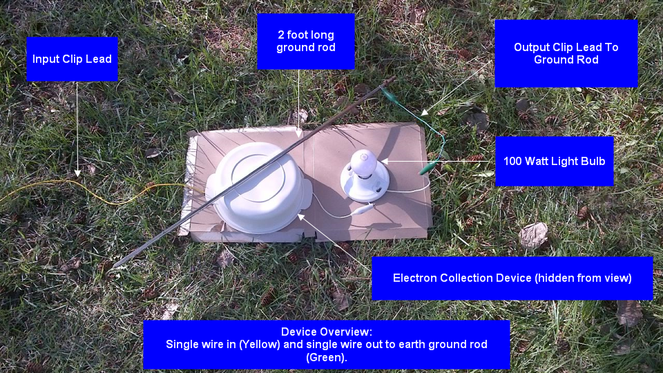
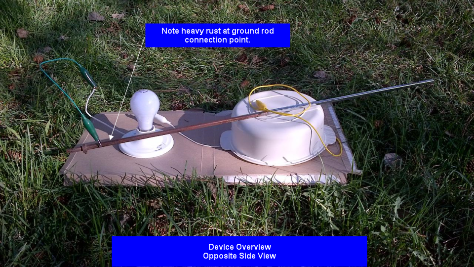
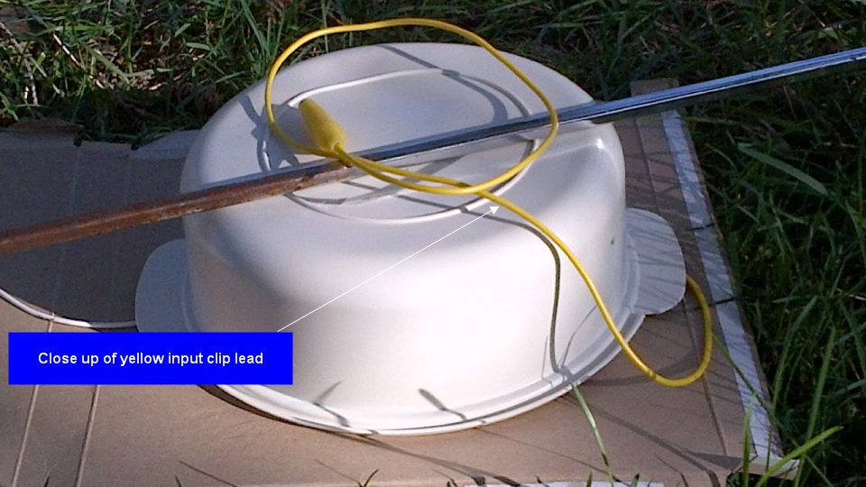
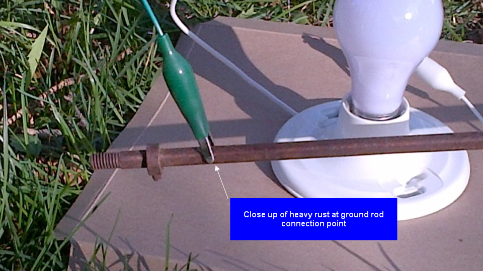
    I have also conducted an experiment that shows that just wrapping an earth ground wire several times around the high current (73 Amps) shorted secondary loop wire on a single transformer Barbosa and Leal device powered by a battery and inverter, does not give any power improvements when driving a load, and does not have any effect on the secondary loop current. There has to be more to it than that or it is an outright deception.

    When a person makes a patent application, the patent application is supposed to be an accurate representation of how an invention is constructed and configured. In the Barbosa and Leal device that was disassembled and documented, they apparently had the ground wire connecting to one side of the load after it wraps around the secondary loop wire, and this is what Clarence incorporated into his own build. Such a wiring configuration was not shown in Barbosa and Leal's patent application docs however, that I can remember seeing. What can we make of this? Appears to possibly be some serious deception going on there. If you power such a device from the mains, you are going to be supplying power to the load via a ground loop back to mains or back to the mains source if it is a SWER system. That seems like a very deceptive thing to do no matter how you look at it. I can't believe that Barbosa and Leal would not be aware of ground loops for that wiring configuration when using the mains, yet they have demonstrated their devices by powering from the mains. How do you see this?

    Last edited by level; 04-30-2015, 10:22 AM.

    Leave a comment:


  • level
    replied
    BroMikey - Agent of Suppression

    BroMikey. Give it up. It's all over. We have your number. You pretend to be one us true free energy experimenters, but we can all see that all you do is make post after post of complete nonsense and blow nothing but hot air here, and you act as completely irrational as you possibly can. You are obviously posting all your voluminous make pretend irrational nonsense here to try and disrupt and bury the truth and free and open discussion about free energy by us TRUE free energy EXPERIMENTERS!!! We all know that no one could possibly be anywhere near as irrational as you present yourself here day in and day out!!! You are a fake, a fraud, and a deceiver, and you have been EXPOSED!!! You have been posting in this thread for over two weeks and you have not shown even one experiment!!! You now see my proven WORKING free energy device and you desperately want to try to suppress my work. It's just not going to work, as you are clearly an agent of suppression, and we the TRUE free energy proponents have exposed you to the WHOLE world!


    ... Seriously BroMikey, start taking your medication regularly and get yourself the help you very obviously need... OK? This thread is for the friendly discussion and sharing of ideas and experimental results regarding Barbosa and Leal devices. People who are unable to communicate respectfully and in a friendly and open manner are not welcome in this thread. Please take your incoherent ranting and ignorant behavior somewhere else.

    Leave a comment:


  • BroMikey
    replied
    Same ole Level horse Sheet alert.

    Level seems to be quite crooked. It is a mind control name "Level" of course he is being chased by the men in black so i had better pack up and head for the hills.

    What a gas, I told you guys this character has slipped his gears.

    Ground control to major Tom

    Leave a comment:


  • kenssurplus
    replied
    All joking and mocking aside, the variations are good to have reported, as well as the performace of such variants. The problem I am finding, is that I don't have a baseline to judge whether the variants are an improvement or not.

    What I would like, but not going to get, is a rundown on where we are with the experimenting and building. Perhaps a short table of devices, a brief mention of their departure from baseline - there's that word again. Perhaps also an actual performance test.

    Since my mind can only focus on and rembember the last thing told it, your post reminds me I need to mow my lawn and Bro Mikey's post reminds me I need to change my flat tire on my car.

    Leave a comment:


  • OrthoParameter
    replied
    take control


    this is your thread level..... you do have a level of control over what goes on here. (pun intended)

    Leave a comment:


  • level
    replied
    Electron Collection Free Energy Device - single wire in - single wire out to ground

    Dear friends. Just wanted to share some photos of my current experiments with my new electron collection free energy device. As you can see in the photos, it uses just a single clip lead wire in to the electron collection device (yellow clip wire), and a single clip lead wire out (green clip wire) to a single 2 foot long earth ground rod, to light a 100 Watt light bulb. With only a single wire in and a single wire out to the (rusty) 2 foot long earth ground rod, we all know what that means... Yep, free energy!!!

    The ground rod has heavy rust on it where the green clip lead connects to it. This seems to show that whatever kind of current is flowing in this wire is not ordinary current. It seems it must be negative/cold current because it only needs a 2 foot long ground rod and it can flow right through rust (the opposite of ordinary current)!!! This is not a trick. There are no hidden batteries or any other tricks. Just one wire in to the electron collection device and one wire out to the 2 foot long rusty ground rod.

    I am a little hesitant to reveal the electron collection device details here because we know there are people here who hate free energy and will stop at nothing to suppress this device. I am pretty sure I saw a black SUV drive by my house a couple of times while I was taking these pictures outside, and I think the men inside were wearing black suits as well. We all know what that means...

    Please don't listen to anyone here who tries to suggest a possible explanation of how my device may be working because these agents of suppression here will say anything to try to make people think that my device is not really free energy. As you can see from the attached pictures, my device is real and it is WORKING!!!!

    Thanks for taking the time to view my free energy device.
    Hope the attached photos show up OK. Best to download these photos to your hard drive right away before the agents of suppression crash the website or whatever else. (Those of you in the know will KNOW what I am talking about). If you don't hear from me again, you'll know what happened...


    Stay strong and NEVER give in to the agents of suppression. Anyone who tries to suggest tests or measurements that you can try to better understand how a free energy device you are working on is working, is OBVIOUSLY not our friend, and we should attack and insult them at every opportunity. It is definitely us against THEM!

    Leave a comment:


  • BroMikey
    replied
    Originally posted by ewizard View Post
    Mikey, Not sure why you are thinking of changing what we know works. Clarence used copper coated ground rods. That works for the long term for electrical house grounding so why change it? It's cheaper and easier than a pipe with a steel rod. Also did you forget the water drill I mentioned. A 10 piece of PVC or copper can make a nice cheap water drill with your garden hose. Also you can usually get the first couple feet of a rod in the ground just by jabbing it in so if you don't use the water drill method (why not?) then you are usually only dealing with hammering a rod starting about 5 feet above ground. Concerns about water in the ground? Clarence mentioned it doesn't work as well after rain but I can assure you the water drill water will evaporate and/or seep deeper into the ground unless you are living on a swamp with a very high water table.
    Yes I remember

    This drill uses that method with water running down the pipe but it turns
    and helps when you hit harder ground. If you live in low country
    drilling is no problem, if you live in the rocks of Nevada or the rock mountains.


    I am in the high plains and is very dry, also known as the dust bowl in the early 1900's. This means that when there is no water in the presences of clay you need a jack hammer to break the ground.

    VERY VERY VERY DRY. Good for wheat fields, the bread basket of the USA.

    My rotor tiller blades dance on the surface of the ground and to get them]
    to cut through is very hard.

    Thanks for the video.

    Mikey

    Leave a comment:


  • BroMikey
    replied
    Originally posted by wantomake View Post
    To All

    This is a joy and great fun for me.

    I still have a cfl and charger running from the setup without draining my battery bank..
    Thanks Wantomake

    Great post

    Leave a comment:


  • PolandKapa
    replied
    @BroMikey: I am new to this topic, and I'm not going to quickly give up even if the project does not work out, this is the next hundreds just waiting to try out. I can not much idea about physics, but I have a non-linear thinking, which allows me unusual to find a solution to common problems of the issues about which I have little knowledge. Besides, I like a few popular themes from the point of view of normal bread eater.

    @Clarence: Could you try to use only one coil on your device. I'm curious results, because the second coil in your project, it seems to me unnecessary. Well, unless it has in some way flow of electrons, and may have already tried this approach and it did not work?

    I have an idea of ​​how close the circuit to squeeze out of your system more energy. Because if I understand this power output is limited by the inverter and battery charger power? Tomorrow I'll put schema that circulates through my head.

    @All:
    Btw. What do you think about Crystal power cells. Anybody got any experience with them.

    EDIT:

    What do you say to such a solution ?

    Last edited by PolandKapa; 04-30-2015, 12:30 AM.

    Leave a comment:


  • BroMikey
    replied
    Originally posted by PolandKapa View Post
    Today I did the first test on the transformer from an old UPS.
    I used only three rods, in addition to steel. But to my surprise it worked, I did not have the equipment or time to carry out the tests, the only thing I've done is to check how quickly rotates counter when directly connected an electric kettle, and through transformer, shown in the photo below.
    Scheme modeled on the link below.

    [VIDEO]https://www.youtube.com/watch?v=lUtRFSqj504[/VIDEO]


    Hi PolandKapa

    Thanks 4 sharing your work and also i want to warn you and all who bring there experiments for review that we have people here who hate this project with a passion, they will claim that you are drawing power from the power company and in this way try to side track the real work here.

    I am going to try your experimental setup also and I think these tests are well worth running and want you to be encouraged. The mockery toward real replicators is becoming more evident and hope you will see through their desire to ruin this project.

    Many people will see a post stating that the experimenters are steeling power from the grid and they will never try after that. This is the plan.

    Your work is very valuable to us and we need to watch one another back.

    Nice going, don't stop the adventure.

    Mikey

    Leave a comment:


  • ewizard
    replied
    Originally posted by Fjohnnyb View Post
    The water drill sounds like a much better idea actually. I was only suggesting the steel rod to make it possible to hammer the pipe Into the ground as I used it before and it worked quite well.
    I'm not trying to discourage anyone from trying other things but I believe it will cost more with copper pipe plus steel rod and there will be a lot of work in getting a bunch of these in the ground. If you have the money and time then it would be of interest to try but we know what Clarence did works.

    Leave a comment:


  • dragon
    replied
    Just as a general overview of what's going on - Let's say we take an inverter, place the Neutral wire to one ground, the line to a load then from the load to the other ground. Quite simple to see the interaction. The load would run as it normally would connected conventionally with the exception of added resistance.

    Since the system uses line voltage, that is voltage itself is not being manipulated, the only other way to increase output power is to increase amperage on that line. In turn increases amperage on the entire circuit, including that which flows through the inverter.

    In order to allow the inverter to simply idle with the torroid loads would be to create a separate circuit using the current loop and manipulate the voltage in that loop.

    Leave a comment:


  • level
    replied
    Originally posted by Rhino101 View Post
    Hello all...
    ... Clarence has on a number of occasions pointed out that he had found many errors "Deceptions" in the original patents. ...
    Hello Rhino101. Glad you made it in.

    Clarence's build is actually pretty close to what is shown in the patent docs, except that Clarence has added the extra earth ground connection to the neutral wire, and he connects the load between the hot and his other earth ground connection.
    This method of connecting one side of the load to earth ground actually came from a schematic posted by a guy on ou.com who took apart a device built by Barbosa and Leal, and then posted up the schematic drawing of how everything was wired in that device. A similar connection method was also included in another schematic by 'zero zero' from ou.com. The only other difference in Clarence's build is he is using power toroids, but Barbosa and Leal did not specify what type of transformers could or could not be used, and they themselves used a large iron stator core toroid from an electric motor for the single transformer device they sold which was later disassembled.

    Last edited by level; 04-29-2015, 08:24 PM.

    Leave a comment:


  • Rhino101
    replied
    Originally posted by BroMikey View Post


    Okay I thought it over and decided that I better do it like Clarence is showing if I want to take advantage of his gift. This should shorten the work up considerably.

    I think I won't use the information from the Patent, well only to get the idea and try to find somebody who is smart enough to undo their lies.
    Hello all... New to this site.... I have read and studied all Clarence's posts both here and on the OU.com site. I have tied to filter out all the rubbish posts etc.

    From what I see (As an outsider) is that Clarence has on a number of occasions pointed out that he had found many errors "Deceptions" in the original patents.

    He has tried to guide others in what he has found, and granted, as Level has also pointed out, Clarence has not given measurements etc. which would be nice to know.. However! that point is, if you want to verify his finding for yourselves, "Do" the experiment!

    I have found Clarence's information enlightening, and it will certainly save me having to try to "Re-invent the Wheel" and play catch-up trying to find the patent errors he has already discovered, and shared.

    I am not saying his system works (because without actually doing it I will bever really know), all I am saying is he is trying to guide us through the mine field.

    Thanks Clarenece!!

    Leave a comment:


  • level
    replied
    Originally posted by PolandKapa View Post
    Today I did the first test on the transformer from an old UPS.
    I used only three rods, in addition to steel. But to my surprise it worked, I did not have the equipment or time to carry out the tests, the only thing I've done is to check how quickly rotates counter when directly connected an electric kettle, and through transformer, shown in the photo below.
    Scheme modeled on the link below.
    Hello PolandKapa. If you are powering from the mains, and you have one side of the load going to earth ground, you are probably just making use of a ground loop back to the mains neutral. You may possibly fool power meters that way, but the power will still be coming from the mains. If you were powering from the mains in your test, and if you want to try a simple test for comparison, you can try not using your transformer at all and instead just connect the mains hot lead (it has to be the hot phase lead) to one wire of the kettle and connect the other wire of the kettle to your earth ground wire, and compare the performance to when you had your transformer connected in. I'll be interested to hear your results if you try it.
    Last edited by level; 04-29-2015, 06:49 PM.

    Leave a comment:

Working...
X