Connecting battery charger
Back on post #982, Clarence has an output from the rectifier. Take the plug on the switch mode battery charger and connect one pin to the rectifier positive and the other pin to the rectifier negative. Connect the charger output to the battery. Do you really need a diagram?
-
What's really funny is that you hot shots never post a working circuit.
Cut with the arm chair command post told ya so and post
something that shows you know enough about this to be
dangerous. Til then it's just parroting flow charts from your school
books. Teacher told me kind of stuff.
Show me a practical well thought out functioning circuit and
try to explain yourselves a little, all of this mumbling and
grumbling is silly.
Can't you guys come up with anything? Even a divider or anything
on paper? All these little digs about you told me so and you are
to afraid to give an example?
It's okay guys don't be afraid. So far no one has any idea
what is in your heads unless they are clairvoyant.
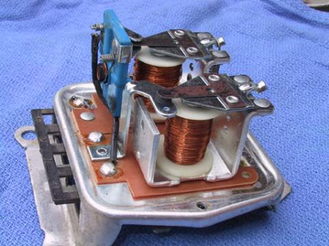
I'm old enough to have had a relay on my car as a regulator.
The voltage regulator on the 60's cars used this format and
I would pop the cover after drilling out the rivets (voiding
the warrantee )and file the point contacts clean again.
It used to be the way alternator voltages were regulated
going to the battery. If I find the circuit, do you want me to
email it privately so you have something to show the group?
You can't just hang a transformer on the unit.Originally posted by SisMika View Post


 Last edited by BroMikey; 01-07-2016, 09:58 PM.
Leave a comment:
-
Hello Bi,
This is really funny.
I suggest a simple transformer also and even told Clarence about using them in radios. But that idea got jumped on big time just like your idea.
So BM who never reads anything already posted then posts a circuit that has TWO transformers and a whole lot of other junk. Talk about a lack of comprehension.
Take care,
SisMikaLeave a comment:
-
Well yes and no. Like say we took a PC power supply and feed
the second stage directly with 120ac stepped up to 170vdc
like it works already okay?
You forgot about the spikes eating that switch mode device up.
The PC supple will use a TL594 in the olden days or an SG3524?
Something like that and the supply is no designed to take that
but could be modified.
Same with all of the junk that's out here for plugging into
nice quiet warm ac power burning circuits.
Show a well thought out circuit. Nevermind, leave it to the boss
Clarence will do them all til he finds the best one for his setup.
A simple divider would have been a quick easy but ya can't have
everything.
The thing i like about regulators is they follow the musical noise
around the circuit and are not so temperamental. I have been
thinking somebody has a simple build on ebay but I haven't checked
yet, however the ZVS came from there I believe. Simple is better
because microprocessors will need shielding plus that is not what we
want here for the average Joe to be stuck with failed digital circuits
he can't repair when they pop.
Where is your design? Speculation? better let the boss take care of it.Leave a comment:
-
idea
Hi Sis,Originally posted by SisMika View Post
I offered some nice polite help back in post #983 and Mr. Clarence ripped me a new one. Looks like those twelve $14 10MΩ resistors didn't work out. Go figure. But I'm sure Mr. Clarence would tell me it is his damn money and butt out. So then we see BM begging you for a regulator circuit diagram. Ain't that something?
How about this? He has 122VAC at some kilohertz. Wants to charge a 12V battery. Guess he didn't like my idea of an old battery charger because the transformer would overheat. How about a new switch mode battery charger? You can feed those DC. So rectify and filter the 122VAC and put that into a 120/240VAC switch mode 12V, 5A battery charger. Regulation solved and cost is less than those MΩ resistors.
What do ya think Sis? They probably won't like that idea either. WTH, back to the sidelines.
biLeave a comment:
-
Here it is again, for some reason the first copy got deleted so
I am posting this schematic again. This diagram is simple to
follow for anyone desiring to close the loop on a SEND/RECEIVE
coil system. So now I will leave you to your own devices
You will see Katcher meaning HV generator.
You will see a 24v supply on the far right for charging batteries.
If the main coil is off then no power is produced in the small coil set
and the regulator is off.
In this circuit he triggers this output MOSFET regulator FR307 with
the front HV generator circuit to be used to toggle the transistor base
at whatever adjustment on the resistor as a what is part of a
"FEEDBACK LOOP". Or you could use a 555 timer circuit to control
the 460 base.
A "FEEDBACK LOOP" is used to follow the main circuit, it's really
not the normal expression of a "FEEDBACK LOOP" but some may
loop at it like one because the number of turns.
In any case this is set up to FEEDBACK some power in the LOOPING.
We are Looping Back or Feeding Back some of the power being
circulated. For instance transformer coil L5 (if you choose to add it)
might draw the main transformer coil right down to nothing if it
were connected straight to the battery. However it is connected
to a 460 mosfet giving you the frequency or current needed.
 Last edited by BroMikey; 01-07-2016, 01:59 AM.
Leave a comment:
-
Hi Clarence.,
thank you for sharing with us all your knowledge.
I read the first 34 page of this forum carefully and I finally believe that this project is feasible. I currently applies to build this project and keep you informed if you want.
Thank you again. God bless you all.Leave a comment:
-
Here is one possible solution that not everyone will try but
get close a dozen other ways.
Enjoy!!
Leave a comment:
-
Okay it appears that Sis is not our secret admirer.Originally posted by SisMika View Post Instead of posting
a possible circuit solution as if we were able to read a diagram we get
nothing but condescending insults. That's how my Sis talks to me too.
I you want to help people this is not the optimum approach and having
said that I begin to realize anyone who is not aware of these facts
might not be as smart as Sis puts on.
Oh well never mind, here, take a seat for just a minute Sis and let me
talk, you are goofing up pretty bad. One more things Sis just because
I called you down for your insulting behavior don't let that stop you
from correcting your error by posting your diagram solution.
Some people are fairly cranky in the cycle of events.")
Okay let's go over the divider. Or the regulator or the transformer.
Yes many designs exist. I learned the hard way like every experimenter
does that sometimes a voltage divider is just to temperamental so
those of us who have lived long enough are not automatically condemning
for trying it.
I have made dividers work great in a circuit and it's just one of those
ideas that may not work every time, come on guys, lighten up.
Coils throw off the already balanced impedance that may have taken
great effort to tune, granted transformers can still be used like
resistors storing energy and damning up the stream or in step down
operation some will add a couple of loops to extract current off the
main winding.
I like the regulators myself but to each his own, but I tried them all.
Others may try them all and we shouldn't beat one another senselessly
when a man is working out in the open and sharing. Sharing is a kindness
and yes it opens us all to attacks, attacks from others who feel it is
better done another way.
We need to work together and share, so if anyone has a simple
regulator circuit and doesn't pull "the Sis" routine that will be fine.
I'll be back with one in a minute.
Originally posted by SisMika View PostLeave a comment:
-
Your real problem is having such an ego problem you won't listen to those that have tried to help you. If you would use a transformer all those problems would be gone. You could probably even use an automotive ignition coil as a step down transformer. Or winding an air core transformer is not that hard either. It is a shame you'll listen to a person who knows nothing instead of those that have some real experience with these things.Leave a comment:
-
No go on the voltage divider
Hello BroMikey,
built the voltage divider - nice and neat per usual but neat doesn't cut in the real world. takes perfection as close as you can get it!
the problem was having to use to many MAX mega ohm resisters. 10 Mohm
was the size I used and it required 12 to get the job done. however with the percentage difference in the whole lot it caused a net deficiency in the end result. missed by a slight margin - however enough to screw up the whole works!
Also there was a lot of constant fluctuation back and forth in the voltage values,
and that would not serve my purpose for the DC going into the battery.
SO
as I said before , if I ran into any problems , I would make a new larger
voltage control/regulator like the photo I showed recently.
This time I will make it larger with more selection connection points to nail the exact end voltage I need before rectifying anything. the smaller one had very little fluctuation to it.
OH well! just passing info and time.
@ ALL - Later!
respects,
ClarenceLeave a comment:
-
Well the New Year has come. Greeting to all......!!
I hope everyone is enjoying any progress each has made
in understanding new energy forms.
I sure am.
And guess what? A secret admirer of DON SMITH and of course
Mr.Tesla has contacted me privately with some early pictures
of DON'S for your review.
It was brought to my attention after I made a post a few days
ago about a statement DON made in his video. Don was talking
about his board components and as DON gave a run down piece
by piece he pointed out his variac.
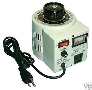
Now this is a standard variac we all have for experimenting with
right? That's right I have several. But this will not work.
It won't you say? Well I would say not because DON went out
of his way to point out his variac and specifically stated that it
needed to be THAT one for the sign transformers.
Our secret admirer may have gone to Don's events or just collected
data way back in the day but regardless here are the early pictures
YOU DON'T HAVE.
How can you stick to DON'S information and not have it all?
We are still gathering the right parts it seems.


Leave a comment:
-
Thanks RS
HI Fer
http://www.energeticforum.com/284427-post10589.html
[VIDEO]https://www.youtube.com/watch?v=-lpbyzTQZag[/VIDEO]Leave a comment:
-
Plasma Power Generator Transformer 1
Plasma Power Generator Transformer 1...
https://www.youtube.com/watch?v=-lpbyzTQZag&feature=em-uploademail.
This may interest those of you in replication...of sorts ?
- Enjoy
Leave a comment:
-
Hello BroMikey, thanks for the reply, I was reading most of your post and I have a nice idea how don smith system in general work, but Mr Clarence is planning to use the volts 12v from the ZVS,TPC,TBC,and the voltage divider direct to the battery circuit and how he will connect to the captor? the other TBC have a high frequency? How he will make it work? Will be nice to see that. Anyways I will be reading and waiting. Wish you the best.
Leave a comment:


Leave a comment: