DC input - AC output ?
I've not heard this before and it has me wondering.
Is this confirmed by actual readings or assumed ?
I can't see how this is so, and the best I can come up with is pulsed DC output. I shall explain.
To be AC, obviously, it has to flip direction. So I'm wondering what the mechanism is for this to happen.
The asymm motors have separate coil groups where the output will be the same direction every time a group passes the generator brushes. And every time a coil group passes the generator brushes there is, presumably, a pulse of electricity. And every pulse is always in the same direction.
To be AC the pulses would need to be reversed 'alternately'.
---S---
On an unrelated thought.
I'm chopping another motor tonight to see if I can get the same amount of wire as the OEM, not in One Pair of Groups but in Two Pair of Groups.
Once I appreciated that approximately 98% of the time the brush covers two commutator segments then I figure I should design based on Two Groups acting together, not just on One Group acting mostly alone.
This wind, if I can fit all the wire in, will have 10/12 of the OEM wire in 1/3 of my motor. In other words there will be 30/12 of OEM wire in the rotor.
Happy Hunting
mark
Announcement
Collapse
No announcement yet.
A1Mo-Gen: Tesla's Gift "The Electromagnetic Reactor"
Collapse
X
-
It's funny because everything is more expensive in Japan than most people think. Also, it's hard to get electric parts and things in Japan. Japanese people usually buy new stuff. They don't repair it. The big companies bought and control EVERYTHING! For example, I can only buy AIW 220c Hatachi wire. The stuff is best quality but to wind the Imperial it will cost you $150 for a 5KG roll or $10 for 10 meters.Originally posted by grounded View Posti dont have a rectifier to try out.
its on my list of things to do.
there cheap. can get them for £1 over here, which is about 200 yen, in japanese money.
Welcome to the party. Well, I got you on AC output but that probably about it! Lol. I'm not sure but it seems like the A1MoGen with extra brushes should run on attract mode when collecting energy. ... Or is it the other way around.im new to all this, so i wasnt aware that a motor-generator always pumps out AC.i just assumed, as DC power was going in, DC would be coming out, but have learnt otherwise. im hoping thats what caused the motor to slow, because i was trying to charge a DC battery with AC.
I'm in the middle of all this but... I only needed a motor for my EV build! Lolyou wont need any teaching - youve got this far with the motor, so youll have no trouble rigging one of them up. its literally the 2 AC wires into the rectifier, and 2 wires coming out become DC.
These motor seem to have there best output from 12v. The 2 magnet motors have 1 output ... the 4 stator s have 2 outputs... The A1mogen with extra brushes, it could maybe possibly be 6 outputs. That would be great If there is 0 magnet drag. I wish I had more experience with generator.Diode bridge - Wikipedia, the free encyclopedia
apparenty each of the 4 diodes that make up the rectifier circuit, steal a bit of power in operation, about 1 volt each roughly, so your looking at a 4v loss of output per rectified channel, which should be minor when the motors upto speed, and kicking out double or triple figures.
but like i said before, im not sure if it will work, im just guessing.
Thanks for that link.
I started reading about the Bedini Motors but I got lost and gave up. Those guys are all about the generation of energy. They would be very helpful.ive seen other people with the bedini wheels do a similar thing tho, so its not impossible, with the right circuit.
my knowledge on electronics and circuits is pretty sh1t. i wish i knew more.
Keep it Clean and Green
MidazLast edited by Midaztouch; 05-18-2015, 11:47 AM.
Leave a comment:
-
i dont have a rectifier to try out.
its on my list of things to do.
there cheap. can get them for £1 over here, which is about 200 yen, in japanese money.
im new to all this, so i wasnt aware that a motor-generator always pumps out AC.
i just assumed, as DC power was going in, DC would be coming out, but have learnt otherwise.
im hoping thats what caused the motor to slow, because i was trying to charge a DC battery with AC.
you wont need any teaching - youve got this far with the motor, so youll have no trouble rigging one of them up. its literally the 2 AC wires into the rectifier, and 2 wires coming out become DC.
Diode bridge - Wikipedia, the free encyclopedia
apparenty each of the 4 diodes that make up the rectifier circuit, steal a bit of power in operation, about 1 volt each roughly, so your looking at a 4v loss of output per rectified channel, which should be minor when the motors upto speed, and kicking out double or treble figures.
but like i said before, im not sure if it will work, im just guessing.
ive seen other people with the bedini wheels do a similar thing tho, so its not impossible, with the right circuit.
my knowledge on electronics and circuits is pretty sh1t. i wish i knew more.
Leave a comment:
-
i missed the " pay to play " .... im dopey
i dont know if its possible to do, but maybe fitting bridge rectifiers on the 4 extra channels, so the regen-energy is pumped back into the 4 feed lines, for motor assist ?
not sure if its possible, without straining the motor tho.
ive tried charging from the output lines on mine, and it slows the motor speed down.
that was charging a DC battery with the AC that was coming out tho, which your not supposed to do.
i havent tried a rectifier on the line, to convert it to dc
Leave a comment:
-
A1MoGen = Singular Coils with Extra Brushes
Motoring only & the importance of #5
Published on May 17, 2015
[VIDEO]https://m.youtube.com/watch?v=9KWvDSNqi-8[/VIDEO]
When choosing a Brushed DC motor, look of a motor that has the "Magic" #5 or greater.
Examples: 20/4 = 5 ..... 12/2 = 6
Number of poles divided by the number of magnets. If the number is 5 or greater.... You can add extra brushes!!!
Keep it Clean and Green
Midaz
I do this for people that my not have access to expert tools! Keep it simple!Last edited by Midaztouch; 05-18-2015, 10:10 AM.
Leave a comment:
-
I got you joke! Right!Originally posted by grounded View Postignore my earlier comment : " it forces you to use smaller coils "
the design wouldnt need changing would it.
i havent barely slept for the last 4 years, so im not really with it.
it should work ok.
it will be firing all over the place tho, left, right and centre - pow,pow,pow sparks camera action lightning smoke and fire, haha
wouldnt it suck alot of juice like that ? firing twice as often, youll have twice the performance, and twice the drain maybe ?
I know your sleepy but... Did you read this part?
Keep it Clean and GreenOriginally posted by Midaz
*You may be thinking, "That will increase power consumption!?"*
Of course! You have to pay to play.
Or
Use thinner wire ......
Option 3: motor can be run in series.
Midaz
I got a vid coming... Don't go to sleep yet! WaitLast edited by Midaztouch; 05-18-2015, 01:38 AM.
Leave a comment:
-
ignore my earlier comment : " it forces you to use smaller coils "
the design wouldnt need changing would it.
i havent barely slept for the last 4 years, so im not really with it.
it should work ok.
it will be firing all over the place tho, left, right and centre - pow,pow,pow sparks camera action lightning smoke and fire, haha
wouldnt it suck alot of juice like that ? firing twice as often, youll have twice the performance, and twice the drain maybe ?
Leave a comment:
-
Extra Brushes for motoring only
When thinking about the Singular Coils = A1MoGen with extra brushesOriginally posted by grounded View Post
i suppose you could just drill into the brush board, and fit extra units, similar to these :
INDESIT WIB111 WIB111UK Washing Machine MOTOR CARBON BRUSHES x 2 | eBay
1 disadvantage of more brushes, would be, it forces you to use smaller coils, which means less high-end power.
on the flipside, as its pinging drive more often, it should be able to maintain the low-end power better.
i have no idea how that will effect the driving characteristics, but my best guess is... it will restrict your top speed.
if thats the case, then maybe changing gear ratio's is the answer, to level things out.
who knows tho, the only way to find out is to test it on your bike in the real world.
First Guildline Spec is... All Coils are the same size as the Magnent
That first spec is flexible. It allows you to do what you think is best for YOUR needs.
For example: 12pole. 2 magnet(size of 5poles wide), brushes (size of one comm segment)
Magic #5 = extra brushes for motoring only works for this example motor!
You either want Max RPMs or max torque... I say, I want it all or as much as I can get.
Keep to the first Guildline Spec....
Option 1: singular coils are the same size as the magnet, 5poles wide, will give you max RPMs
Option 2: each armature pole is wrapped/wind completely with one singular coil...It give you max coil magnetic field strength (DADhav , see, your style is all good too! )
)
*When you add extra brush you get more torque and more RPMs with both options.
*You may be thinking, "That will increase power consumption!?"*
Of course! You have to pay to play.
Or
Use thinner wire ......
Option 3: motor can be run in series.
Conclusion:
If you want to Hot Rod at full power, extra brushes add to the fun
If you want to drive all day to a nice location, thinner wire and extra brushes give you a higher top end for highway speeds.
Keep it Clean and Green
Midaz
Are my thoughts, my fantasy or can it be done... Singular Coils with extra brushes IS a real game changer!Last edited by Midaztouch; 05-18-2015, 05:00 AM.
Leave a comment:
-
i suppose you could just drill into the brush board, and fit extra units, similar to these :
INDESIT WIB111 WIB111UK Washing Machine MOTOR CARBON BRUSHES x 2 | eBay
1 disadvantage of more brushes, would be, it forces you to use smaller coils, which means less high-end power.
on the flipside, as its pinging drive more often, it should be able to maintain the low-end power better.
i have no idea how that will effect the driving characteristics, but my best guess is... it will restrict your top speed.
if thats the case, then maybe changing gear ratio's is the answer, to level things out.
who knows tho, the only way to find out is to test it on your bike in the real world.
Leave a comment:
-
Singular Coils = A1MoGen
5 is the magic # for motoring only
The reason I said that 5 is the magic number for motoring only is... You can add extra brushes!
The goal is to increase the overall performance of your brushed DC motor without creating magnetic drag...
While working with what you have available, cheaply and effectively! Keeping it simple as possible for maximum enjoyment.
Take the number of poles and divide it by the number of magnets. If that number is 5 or greater, you can add more of the same readily available OEM brushes to your already existing brushed DC motor!:thumbsup:
Example. 12 pole, 2 magnet, brushes the same size as 1 comm segment.
12 divided by 2 = 6. .... 6 is more than 5. You can add extra brushes.
Why extra brushes?
Advantages
1.) you at the very minimum you double coils to power the load
2.) double the "throw out" angles = more RPMs
3.) can use a thinner wire to lower the amps draw
4.) more coils being powered = more torque
It's just a simple DC motor.
Disavantages

Keep it Clean and Green
MidazLast edited by Midaztouch; 05-17-2015, 09:55 PM.
Leave a comment:
-
Good to know Midaz. But blowing up a few $3 PWM's sounds like a better learning curve.Originally posted by Midaztouch View PostThey are very popular on the EV site forums... Best value, dollar for dollar.
I do like the idea of their controller with regen, but I think I want to keep it simple at the beginning.
Happy Hunting
mark
Leave a comment:
-
Originally posted by HuntingRoss View Post[IMG]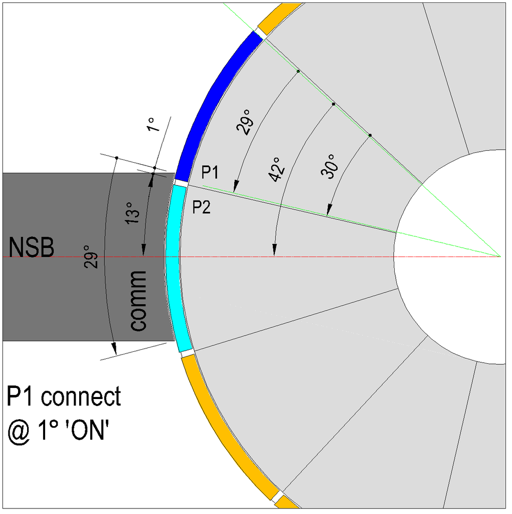 [/IMG]
Image 1 - P1 connecting.
[IMG]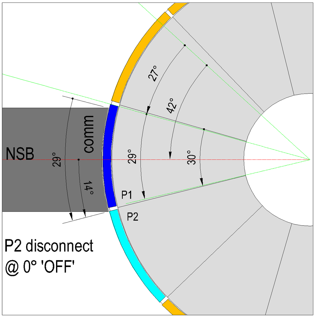 [/IMG]
Image 2 - P2 disconnecting.
[IMG]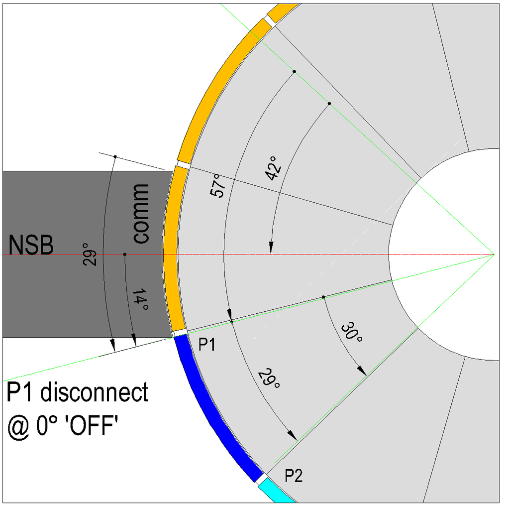 [/IMG]
Image 3 - P1 disconnecting.
*This post does not involve single or double commutator motors.
*This post only considers the relationship of the commutator segment(s) and a single brush to establish the critical sweep angle from connection to disconnection.
*These images are for a 12 pole rotor 30° per pole.
*The angles are whole numbers only.
*The brush is equally divided by the North Stator Bisector.
*The brush is the same width as the comm segment, 29°.
*The images indicate a 1° angle of separation between the comm segments.
*The 'ON' and 'OFF' angles are assumed to be 'ideal' at 5° and 20° respectively.
An explanation of the figures :
Image 1.
P1 leading edge has connected by 1°. P1 trailing edge is 29° behind the leading edge and is 42° above the NSB.
Image 2.
P2 trailing edge has disconnected by 0°. The image has advanced by 27° from Image 1.
Image 3.
P1 trailing edge has disconnected by 0°. The image has advanced by 57° from Image 1.
The critical angles :
Depending on the winding of the chosen design, single, pairs or groups the angle between the first and last coil bisector must be added to the sweep angle plus the 'ON' and 'OFF' angles.
Example 1 - P1 analysis. A 4 pole pairs winding on this rotor has 120° between the Coil 1 and Coil 2 bisectors. P1 Coil 1 bisector is set to be 'ON' at 5° past the NSB and accordingly P1 Coil 2 bisector is 'ON' at 125°. For P1 to disconnect it must advance 57°placing the 'OFF' angle for P1 Coil 1 bisector at 62° past the NSB and accordingly P1 Coil 2 bisector is 'OFF' at 182° past the NSB. This is 22° past the 'ideal OFF' angle and 2° past South Stator Bisector (SSB) before disconnection. It is concluded a 4 pole pairs wind is not viable for a 12 pole rotor.
Example 2 - P2 analysis. The same 4 pole pairs winding. P1 Coil 1 bisector is set to be 'ON' at 5° past the NSB. Accordingly P2 Coil 2 bisector is 'ON' at 155° past the NSB. For P2 to disconnect it must advance 27° placing the 'OFF' angle for P2 Coil 2 bisector at 182° past the NSB. Both methods achieve the same result and the conclusion is inevitably the same.
Example 3 - P1 analysis. A 5 pole single coil winding. The coil bisector 'ON' angle is 5°. The bisector has to sweep 57° before disconnection giving an 'OFF' angle of 62°. Adding an 'ideal OFF' angle of 20°, 82°, leaving 98° for timing adjustments.
Happy Hunting
mark
Ross made the singular coil CAD as clear as day to read.
1.) just connected
2.) halfway
3.) just disconnected
Just the way I said it before the argument about singular coils!.. I didn't deserve the BS from UFO. He needs to apologize to Mark, myself, administrators and all for his huge misunderstanding!
Keep it Clean and Green
MidazLast edited by Midaztouch; 10-03-2015, 11:42 PM.
Leave a comment:
-
For the simple Brushed DC motor we are using, please look at these inexpensive and well built OEM style PWM controllers:Originally posted by HuntingRoss View PostThank you John.
That was mostly outside of my comfort zone, but by the time I'm finishing off this series of tests I will be moving into that area and will need to get to grips with it.
I have one more planned motor wind with testing before I put the winner back into the modified scooter (bigger back belt cog) to see how it performs. The outcome of that will translate into my 12" 120 tooth rear wheel project which still requires a platform to mount it on...another work in progress.
And those cheap PWM's sound like a real find.
Please keep the thread updated with your results.
Happy Hunting
mark
Kelly KDS Mini Brushed Motor Controller - Hub & Wheel Motor Controller | EV Parts
They are very popular on the EV site forums... Best value, dollar for dollar.
Keep it Clean and Green
Midaz
Leave a comment:
-
Thank you John. That was mostly outside of my comfort zone, but by the time I'm finishing off this series of tests I will be moving into that area and will need to get to grips with it.Originally posted by DadHav View PostHey Mark, Make sure you let me know if you make a video about what you're talking about. Maybe I can help you figure out a few things or refine your test. Cap dump circuits are very popular with pulse circuit experiments and there are many techniques. I've never experimented with anything on the level of an Imperial motor though. I might have something to offer on a small scale to help people experiment and understand on an inexpensive basis. I have some small PWM modules on their way and what's unique about them is they are only about $3.00 US and they are a low frequency device that can have a frequency setting as low as 15 seconds if necessary. The output transistor should be capable of driving an FET for cap dumping so it could be fun for cheap. The closest thing I'm having success with is my brushless motor/generators and will try the module on them. They probably will have a similar effect as the brushed motor/generators being made here. Since these are individually wrapped stator legs they can have 6 coils for prime mover and 6 for generator. Now I could be wrong but the effect is similar between both (maybe) . Even though the generator coil is completely isolated from the generator coil it has a transformer effect from the motor coil. When I look at a scope trace I see a smooth sign wave from the transformer effect and then a high voltage spike. After rectification I can watch the capacitor charge and it charges very rapidly from the transformer voltage then very slowly charges the capacitor to the additional high voltage of the radiant spike. When you get into it further you might see nearly the same thing. Well wait a minute. Maybe I can hook the dump circuit to the little 5 pole motor just for fun. I have to think about that. If you are getting higher voltage than your battery from a generator coil that isn't in series with the motor coil then that might be special and work that way. I would have to run the series setup to get above input voltage. OK now I'm just thinking out loud. I'll let you know if I get anywhere.
John
I have one more planned motor wind with testing before I put the winner back into the modified scooter (bigger back belt cog) to see how it performs. The outcome of that will translate into my 12" 120 tooth rear wheel project which still requires a platform to mount it on...another work in progress.
And those cheap PWM's sound like a real find.
Please keep the thread updated with your results.
Happy Hunting
mark
Leave a comment:
-
Originally posted by HuntingRoss View Post
There are three images in this sequence showing the 'sweep' of P1 comm across the brush. The point I'm laboring is the leading edge of P1 energising the coils and the trailing edge of P1 before it disconnects from the brush.
Key points -
The OEM setting for the brush is the same size as one commutator segment
Start: Just connected
Image 1 shows the leading edge of P1 comm 5º on the brush. The trailing edge of P1 has still to sweep 30º to be in the same position. The coils are energised.
[IMG]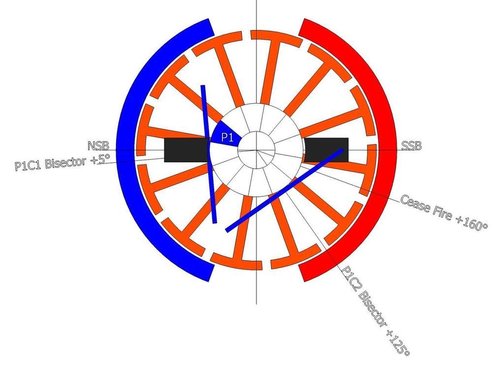 [/IMG]
Halfway
Image 2 shows P1 comm advanced by 30º. The leading edge of P1 is 5º past the brush. The trailing edge of P1 has 25º to sweep before leaving the brush. The coils are still energised.
[IMG]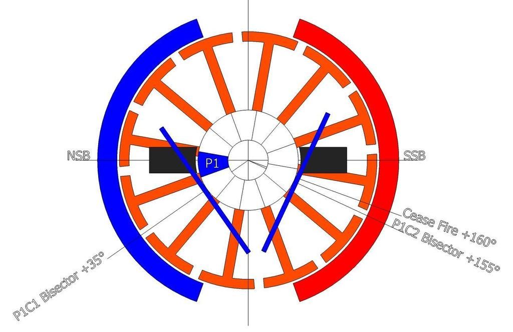 [/IMG]
Finished: Just disconnected
Image 3 shows P1 comm advanced by 30º. The trailing edge of P1 comm left the brush 5º ago. The coils are now disconnected.
[IMG]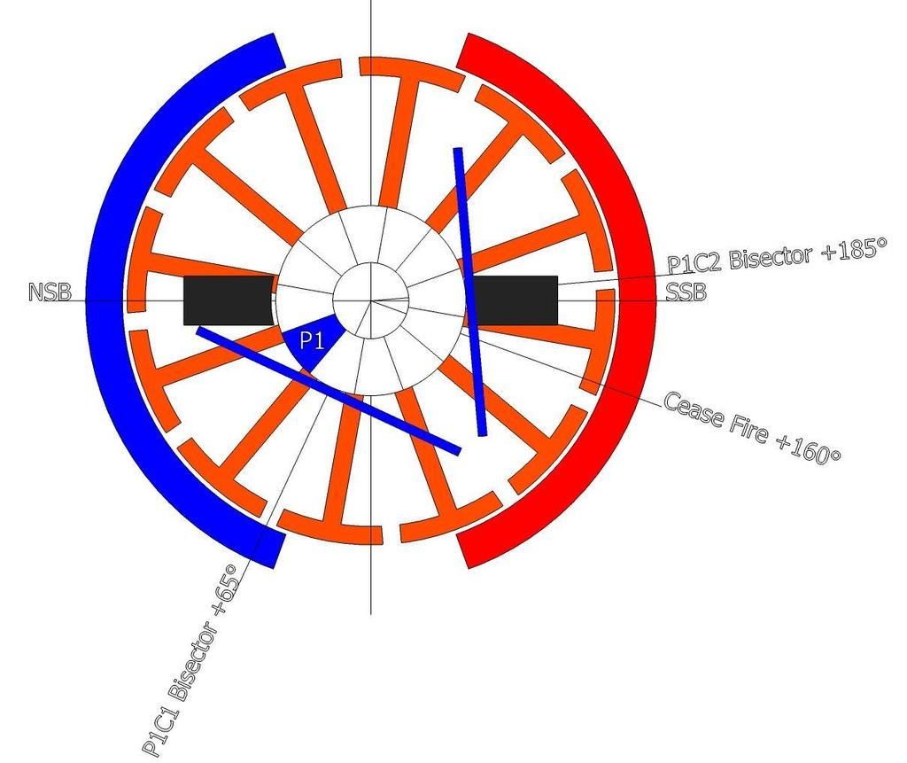 [/IMG]
So with P1 sweeping 60º the P1C2 bisector is at +185º past the NSB and the trailing edge disconnected 5º earlier. Giving P1 comm a total energised sweep angle of 55º.
Hopefully this clarifies what I've been saying... I have to say I have studied this and studied this and I can not see an error.
Happy Hunting
mark
Ross made it so simple to see and understand!
Think in three frames and you will not go wrong.
1.) Just connected
2.) Halfway
3.) Just disconnected
Keep it Clean and green
MidazLast edited by Midaztouch; 10-03-2015, 11:39 PM.
Leave a comment:
Leave a comment: