-
-
Tesla cone coils
Maybe this is the answer:Double Cone Bipolar Tesla Coil
would be fun to experiment with....Comment
-
Yeap, thanks, I don't build OTHERS VISIONS anymore. No point since I haven't any idea what the goal is for the project nor whats been built to date. I did try and share some observations but you blew past those as though they were nothing, so thats ok.
Take care!
Gene
Originally posted by med.3012 View PostComment
-
thanks, i saw this coil before but i don't have experience with it.Originally posted by Dfortune View PostComment
-
ABSTRACT Displacement Current is the criticalOriginally posted by genessc View Post
“ingredient” in recent antenna designs such as the
CFA and EH. Its existence was postulated in the late
1800’s to explain how Alternating Current (AC) could
flow between the plates of a capacitor. In this article,
we analyze the charge-based model of the capacitor,
and attempt to prove that the model is seriously flawed,
and perhaps show that Displacement Current does not
exist.
more reading is here :
http://www.asps.it/miller00.pdf
maybe everyone on this forum know what is the self capacitance of solenoid coil, take a coil with 10 turns for example, the problem with this kind of capacitance is its disfiguration... meaning the turn number 1 will make a capacitor with turn n 2 the result capacitor will make another capacitor with turn number 3 at the same time n1 alone will make another capacitor with n3 alone !!! how many capacitors exist in this model ?
when using the E-TBC in Colpitts oscillator it show a high stability in 14.3 MHZ even thought the stray capacitor is the problem in high frequency region, the circuit i used was taken from the following website, the frequency used is about 7.8 MHZ, compare it with our graph showing a perfect sin wave in about two time that frequency.
makeRF: Experimenting with Colpitts OscillatorsComment
-
Moving the E-TBC in higher frequency around 20 MHZ
the E-TBC that gave a frequency around 20 MHZ ( maybe more than 20MHZ) was built using 14 cm length foils X 5 cm width wound on 3.5 cm PVC tube giving about 1.3 turn, i just verified the standing waves using a small neon bulb and it show the brightness point on the edge of L2 coil and the darkness in the middle, i built a coil using 5 meter wire just to see how much length needed to achieve a quarter wave electrical length.
i am wondering if a small neon bulb is the best to detect these standing waves ?
the following oscillation graph is the highest frequency measured using a digital scope ( Colpitts circuit ) .
maybe the next step is trying to recharge a battery using these waves.Comment
-
Improving the quality of oscillation :
in high voltage oscillation the E-TBC need a parallel capacitor to work with, it's the Yellow capacitor in Don device, i think this is why he used High voltage probe which are of course very expensive

in the following video he said it help for regulating L1 coil , so it's not for resonance !
https://www.youtube.com/watch?v=4af39u1IyF4
in the same video he clarify that L1 is able to setup its resonance without problem which mean it's an E-TBC
what do you think ?
i am wondering about spark gap distance, what is the best gap distance for high voltage spark ?Comment
-
Hi Med
Been a while since we talked, Good to see you posting your progress. You have broken the frequency barrier with the culpitts oscillator.
When it comes to standing waves with some experiments Ive seen with helical resonators one end is hot and the other is not, is it with your E-TBC that the inside is hot the outside is not, but the neon can only access the voltage node from the edges?
I would have liked to have been more helpful but for now the best I can do is try to learn.
The last picture you posted with the two yellow caps, are those two long black things next to them diodes? If so, caps, diodes. and a type of sparkgap connected and that close together,, now Im confused.
I did download the video linked (thankyou ) so I will take a more panoramic view at that.
About spark gaps, how do they work. Does widening the gap lower the frequency, or does quenching the spark raise the frequency. I also cant help but be curious about the typical frequencies one might expect from a spark gap.
One last question, is it just me or is the resonator winding in some of Mr Smiths devices missing or covered over with an insulative layer so its not easily seen?
Thanks
LotecComment
-
Hi Lotec ,
nice to see your post :-) , Don used some kind of helical antenna dipole where every part form a quarter waves electrical length , the two parts together form a half antenna dipole , one of them will take the back EMF so he could unify both the voltage and the current to be present at the same time , when the voltage is high on the edge the current is almost zero ( in center tap) but when the electromagnetic wave collapse the current is high but the voltage will driver an opposite component , this is why ( my point of view ) we have to use twin coil to combine voltage with current.
i am still not confident with the test i did using small neon light bulb because i got the lighter points when the E-TBC was inside a plastic PVC and L2 coil wound on it, when removing the plastic tube these points with high lighting gone ! meaning the plastic dielectric was a part from the phenomena, the electrical component of the electromagnetic waves prefer high dielectric material to penetrate in it .... from the edge i count 13 turns and i found these node point where the voltage is almost zero ! ( maybe i need advice from Antenna expert )
but when the plastic tube removed to form an ideal air coil these points gone but the power still exist meaning the small light neon bulb is less sensitive ) here i have to mention the equipment Don used ... for example high voltage probe , high voltage high frequency generator , sophisticated LC meter, oscilloscope ... and a lots more to work effectively in RADIO FREQUENCY environment
the yellow cap was intended for regulating the oscillation of L1 coil, the problem with spark gap is the dumping oscillation and its quality, to achieve this situation we have to satisfy the condition of under dumping oscillation where the square resistance of spark gap when firing have to be
in practice the resistance of spark gap have to be around 200 OHM ( my calculation ), this mean the distance of the gap have to be small in other hand a parallel capacitor ( yellow Don cap) will help to achieve a reasonable oscillation under these critical conditions, the position of spark gap can be before the yellow cap if direct resonance condition is achieved which lead me to think the inventor used a relatively high frequency module to driver his combination, in my case i use NE555 driver circuit which work around 12 KHZ , it's a low frequency and direct resonance is very very difficult to be achieved, maybe later i will use ZVS driver to achieve higher frequency.
the distance of spark gap will not affect the resonance frequency of the E-TBC but it can affect the condition of oscillation as discussed above.
about the E-TBC it's very easy to be hidden because it take the form of PVC tube , but notice this video
Конференция Смита - YouTube
where someone from the audience ask the inventor to take a measure from his device, Don noticed he want to take a resistive measurement .... so he said it will fry your multimeter.......
it was clear Don prevent taking measurement of his device ( he did it nicely )
Last edited by med.3012; 03-06-2015, 10:03 PM.Comment
-
Originally posted by med.3012 View Post
here i think i am confused too ! i think there is a hidden schematic in Don device, after all we don't have to replicate his device literally, it's better to go our own way, since the process of amplification and multiplication is known the last step is just tuning.
Comment
-
Hi Med,
Thanks again for your patients and explanation. I was looking at the circuit on page 3-23 under the Don Smith device. Looking at it that way it made a lot more sense. (although I havnt worked with high voltage primary tanks, I still have that to look forward to.)
I think what confused me was. I might have been expecting a step down before the output. The coil as it looks seems like it might step it up a bit.
If I dont have any joy with the oscillator I am working on I will try a culpitts too. I got the data sheet for the npn you are using. One day I hope to stumble across an npn with a bit more power than a signal trans that can cope with those kinds of frequencies.
All the best
Lotec
edit I think I saw that one, thanks for the link. I think he would not mind if his meter blew up cause he had a whole bunch of them.Last edited by lotec; 03-07-2015, 12:36 PM. Reason: slow connection picture of the guy wanting to measure loadedComment
-
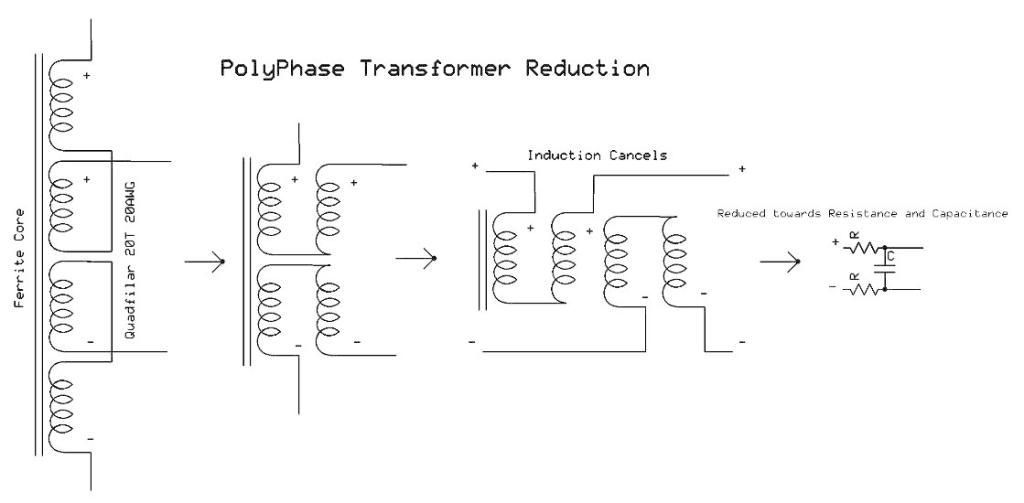
STEAP - PolyPhase Transformer Reduction
Hello Med,
You might be on to something here. Take time to review the STEAP concept from Michael J. Nunnerly on the forum.
He uses a quadrifilar which he calls a "Polyphase transformer". Review this schematic. Basically a set of 20turn bucking inductors to create capacitance. I see similarities here with your E-TBC.
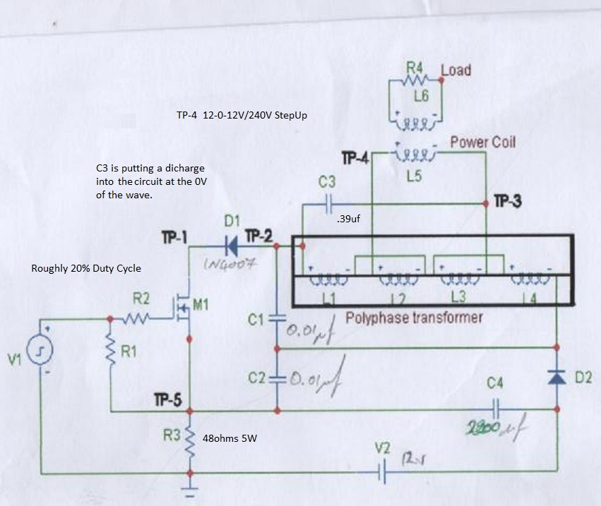
Here is the reduction of the poly phase transformer, at least the way I see it.
Your answer for extracting energy is from the power coil. There is energy multiplication happening here at the standing wave in resonance. C3 and L5 are in series LC while the polyphase transformer, acting like capacitance is in parallel LC. You have both series and parallel LC happening at the same time. There is parametric qualities to this schematic as well, just like you have found out. So you will see multiple resonance points happening at the same time.
The energy is between L5 and L6 at the power coil! You will have a null point in the middle of L5, but considerable amount of energy magnification on L6.
I believe voltage and current are working together in this arrangement to extract.
There has been reports of this schematic using two TBC to generate enough power to run a 110V bulb at full brightness and returning energy back to the source battery, running for free. I can't put my head around how to implement two Tesla bifilar pancake coils on this schematic yet, so I don't quite understand how this was accomplished. Needless to say this is OU, and can be validated if you really take the time to tune.
Hopefully you can see the similarities between your E-TBC and this arrangement as well as learning how to extract the energy. I'm learning more and more to learning how to combine series and parallel resonance together. You are correct voltage and current together is not what we want, but we need to pull energy only from the magnetic or the electrostatic side only and convert into real power, watts, with the source input seeing little combination of both forms of energies combined. As you have discovered, it's the voltage that does the work, or the magnetic that does the work, once you put these together, you working in normal hot electricity.
Hope this helps.
JeremyComment
-
Originally posted by lotec View Post
You are welcome, high voltage is expected from L2 coil but Lesser voltages can be obtained at intermediate points along the length of the L-2 coil, in this case L2 turns can't be reduced because back and forth waves need the exact L2 length.
if you want to work with Colpitts design in high power, it's better to use Power MOSFET, i think it's difficult to find a high power transistor with higher speed into 20 MHZ ranges.
i lots of work is waiting
Comment
-
Hello Jeremy,Originally posted by jerdee View Post
Thank you very much for you post, as you noticed it's important to separate voltage and current in power amplification stage, the E-TBC is an electromagnetism device with a special electromagnetic feedback inside, if you start with electric power you will end up with electric power amplified during the stage when the current grow! the same if you start with magnetic power you will end up with current amplified when the voltage grow, this explicate the energy equation of this device since the voltage do the job, ambient background supply current and the square of frequency is the speed of multiplication.
in my point of view the E-TBC is not series and parallel resonance , but it combine series and parallel to be series/parallel system both in the same fashion !
you comments and analysis are welcome including the schematics you post, it worth to be tested .
thanks once again.Comment
-
using short waves Radio !
Using short waves Radio to see the frequencies when the E-TBC oscillate isn't a bad idea , but short waves Radio show a variety of frequency starting from 1MHZ into 20 MHZ ranges...
harmonic waves exist which mean there is interference inside short waves Radio or maybe outside in the E-TBC ! what do you think ?Comment
 Tweet
Tweet

Comment