Announcement

Collapse
No announcement yet.

Basic Free Energy Device

Collapse
This topic is closed.
X
X
 
  • Filter
  • Time
  • Show
Clear All
new posts

  • altrez,
    It IS simple. That is what I don't think people really understand. We HAVE all the pieces. We just need to put them all together. If you look at the threads I have TRIED to start on this forum, this thread, the "3BGS" thread, and the "All About Your Basic Coil" thread have all been devoted to one purpose...talking about the basic, simple components that can be assembled to put together a machine that works. The "All About Your Basic Coil" thread was to talk about the "Energizer" portion of this basic setup. If we want to produce electricity IN VOLUME we need to add an energizer to the mix, and use the motor to run it.

    That energizer needs to have some very specific parameters. It needs to produce as MUCH power as possible, or a SPECIFIC amount of power based on its application and it needs to be "low drag". We have heard this term before, but I want to be more specific about it.
    1. It needs to as be Lenz free as possible, which means producing as little back EMF as it can be engineered to produce, and engineered to produce it when it hurts us the LEAST. You may not be able to eliminate it, but engineer around it if you can.
    2. It needs to have as LITTLE magnetic attraction between the core material and the rotor magnets as possible, and if you can, control WHEN that happens (with electromagnets you have SOME control)

    And then there is the Thaine Heinz Effect, or the so called speeding up under load. I have seen this Many, MANY, MANY times. I have a video of My generator doing it with just two coils...one running as a generator coil, and the other shorted out to speed it up under load. But to show that video here, I would have to show my generator, which I am not ready to do yet, because it is not finished. Here is a video of someone ELSE doing the same thing:
    https://www.youtube.com/watch?v=fJl0TO_aR6M

    On my generator I do NOT have The Leedskalnin U shaped coil cores, nor do I have the two coils connected together in series as in this video, so there are other configurations that will accomplish the same thing. And realize this will ONLY work with resistive loads, NOT inductive loads.

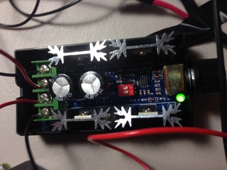
    You don't build a coil that meets the parameters I have talked about here the first time out of the gate. (Unless you have the luck of the Irish) You build it by experimenting and experimenting and experimenting. You try different sizes of wire, different lengths of wire, different wrapping and twisting patterns, different coil cores. I have built hundreds of coils. I can show you pictures if you don't believe me. I have shelves full of them. I have a huge box full of copper wire from discarded coils. I have a coil that appears to be working for me, but I have ideas on how to improve it. I have built a unit to do NOTHING but test the output of coils, so I can turn a rotor by running a motor at a specific rpm with a known voltage and amperage, and see how a particular coil affects the RPM, the amp draw of the motor (kinda the same thing) and how much voltage and amperage it will put out to a known load.

    I have been working with some core materials lately that are flat amazing. I have gotten free samples from a company, and they are providing me with enough of the material to rebuild my prototype. This will also give me that opportunity, as much as I hate winding coils, to rewind my coils in a more efficient configuration.

    I wanted to get a BUNCH of people involved in this testing process because it is as expensive as heck, and I don't have the TIME to do everything. Right now I am incredibly busy, but by the first of the year I will be in a position where working on this stuff will once again be my full time job.

    In my opinion, it is not enough to have something that "works." If I am going to put something out there for people to build, I want it to be bullet proof. I want it to be so simple that if it is done CLOSE to the way we say to do it you will get the results we say you will get.

    Like I said at the very beginning of this thread.

    The BEST, most efficient motor we can find
    The BEST energizer we can build
    A flywheel
    Some batteries to power it up
    A control circuit.
    Run it on the 3BGS setup

    Look at post #3312 On "The 3 Battery Generating System" Thread
    I made that post on July 21, 2014.
    I talked about uses for the 3BGS and I talked about EXACTLY the same thing.

    WHY you ask?
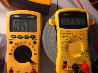
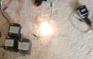
    Because I have Matt's pulse Motor running an Energizer I spent a couple thousand dollars to design and build. I have a flywheel on it. I can run it in the 3BGS setup. I can MEASURE inputs and outputs. (And these are outputs to known loads where I measure the voltage and amperage) I can see how long the batteries last. I can see how much power I get out of the system. I have been working with this generator for well over a YEAR now. I can do the math.

    To paraphrase what they used to say on the old Six Million Dollar Man show
    "We have the technology. We can build it"
    “Advances are made by answering questions. Discoveries are made by questioning answers.”
    —Bernhard Haisch, Astrophysicist

    Comment


    • Originally posted by Turion View Post
      altrez,
      "...It IS simple. That is what I don't think people really understand. We HAVE all the pieces. We just need to put them all together.

      To paraphrase what they used to say on the old Six Million Dollar Man show
      "We have the technology. We can build it"
      You are very right and I think you are working really hard to get more people involved. I know sometimes you want to just walk away but you are getting through to lots of diffrent people. You have a great Idea and I plan to put all my resources into construction the project. We also need people who can work on each part of the system and fine tune it as much as possible.

      Once I have a successful 48 hour test of the Switch / 3BS I am going add a 24 coil energizer and tweak it out as much as possible.

      Thank you for all your hard work and guidance!


      -Altrez

      Comment


      • I left out something about my Tesla Switch setup that I feel is important. If you have noticed on some of my screenshots I have 9 batteries 1-3 1a-3a 1b-3b. I feel this is key to pushing the Switch setup into COP > 1 or more

        I have not fully tested it yet but the argument is sound. You have 3 Tesla Switches / 3BS systems hooked together cycling between each 1 at a time. Once I have figured out the best length of time I will automate the switching.

        In my testing I have found out that the batteries need a off duty cycle of a certain interval to really show the true potential of the setup. With 3 switches hooked up as one you always have power to the energizer it should work extremely well.

        Its the power of 3 and 9!

        I am ordering more data logging equipment soon so I can verify it all not just on paper but post real data of the output over time to prove that I am right on this.


        -Altrez

        Comment


        • Originally posted by altrez View Post
          You are very right and I think you are working really hard to get more people involved.
          But involved with what exactly?

          I thought this thread was for a new arrangement of the basic components, battys, motor, energiser, driving cct etc that had special benefits, maybe simplicity.

          If so, then surely discussion of everything else needs to be taken elsewhere so that those who remain can keep a focus and get the job done.
          .

          Comment


          • Originally posted by wrtner View Post
            But involved with what exactly?

            I thought this thread was for a new arrangement of the basic components, battys, motor, energiser, driving cct etc that had special benefits, maybe simplicity.

            If so, then surely discussion of everything else needs to be taken elsewhere so that those who remain can keep a focus and get the job done.
            .
            We are working on it a bit at a time. On the battery part I am working on the Tesla Switch using 9 battery's from Amazon and some simple switching. We have the off the shelf Razor scooter motors and I am working on a simple energizer.

            A lot more needs to be done but the basic schematic really does not need much explaining IMHO.

            When I have posted all of my data of the battery setup and prove how well it works then anyone can just use that setup and put it together in less then 1 hour.

            We need the same on each part of the system. And then we tweak the whole system or at least thats how I see it.


            -Altrez

            Comment


            • wrtner,
              Basic components as I have been saying for a while now, and John B has said since it was published it in the Free Energy Generation book:
              Batteries
              Motor
              Energizer
              Flywheel
              Switching

              all I added to that is running it on the 3BGS setup, because I have seen what that can do. And where do you think THAT original schematic came from?

              If you have a solar setup or any kind of setup where you are cycling batteries, It is ALWAYS best to have one under load, one charging, and one resting after charge. That's a total of 3 batteries. Altrez has taken this to the next step, where he is using three groups of three, and is looking at running just the motor with the batteries WITHOUT discharging the primaries. It's a Tesla switch type setup. I happen to KNOW that the 3 battery setup works because I have tried it. And you don't have to GAIN charge in your batteries. If you can just break even, you will get the benefit of the energizer for FREE. I have had REALLY LONG RUNS with manual switching. You can cycle the batteries manually or with a microprocessor. But you need that rotation so that the batteries don't lose charge. THERE MAY BE A BETTER WAY THAN THE 3 BATTERY SYSTEM. That's why we need people trying this. But the 3BGS is where I have spent the last EIGHT YEARS of my life, so I feel confident when I talk about what it can do. I'm NOT saying the primaries will charge or even that they will keep from discharging (VERY slowly), but with a little luck and close to the correct timing they should hold their own. Which means the motor turns the low drag generator (basically) for free. SO even if they need to be rotated out once in a while, who cares...the energizer has been going strong the whole time. We NEED more research done on this switching.

              THEN, we need more research done on the motor. Which is better...an off the shelf motor or a modified pulse motor? I have used Matt's modification of the razor scooter motor with GREAT success, so I am sticking with it until I find something better.

              Then the energizer. Here is where the MOST work has to be done, and I talked about that in my last post. Now if you do what John B did, and run your energizer AS YOUR MOTOR, you have even MORE issues to deal with on the timing side of things. When to fire, what distance between magnet and coil...all the things explained in the Bedini SG handbooks. There are benefits and disadvantages to that. I wanted simple, things anybody could do, so I was keeping them separate.


              Dave
              “Advances are made by answering questions. Discoveries are made by questioning answers.”
              —Bernhard Haisch, Astrophysicist

              Comment


              • Originally posted by Turion View Post
                THEN, we need more research done on the motor. Which is better...an off the shelf motor or a modified pulse motor?
                Very nice position statement.

                Bearing in mind that JB has stressed many times that with his 1984 device, and the Watson variant of it (i.e. the same but a darned sight bigger) that the motor needs to be field wound DC, maybe that is a good starting point.

                I have burned my fingers on car starter motors. They qualify and are capable of immense current but the bearings are rubbish. Who uses DC field wound motors in an inexpensive consumer product?

                Comment


                • wrtner,
                  I assume that whatever motor was used for the Watson Device, it was wound for the lowest amp draw possible for THAT SPECIFIC USE, and the purpose of the wound rotor and stator was so that it would "freewheel" during the off time.

                  So let me address the difference here between using a motor with wound rotor and stator vs one with permanent magnets on the stator IN THIS DEVICE ONLY, and NOT THE ORIGINAL WATSON MACHINE. The main difference here is that we will be running the motor in the 3BGS configuration. What does that mean? It means that the generated current produced by the motor whenever it is running, instead of being forced back against the input current flow, actually has an outlet because of the way we run it between two negatives. Measure the voltage into the motor and out of the motor on the 3BGS when it is running, and you will see an increase. So in the OFF time it is still generating current to charge the batteries. In the Watson device it was NOT being used as a generator in the off times, so that generated voltage would have been wasted. Hence a NEED to have NO influence on the rotor by the stator in the off times. Does that make any sense?

                  Of course, this is just my opinion, and I have been wrong once or twice in my life.

                  (Damn Matt, you get up TOO early on a Saturday! Go back to sleep!!)
                  Dave
                  Last edited by Turion; 11-01-2014, 02:13 PM.
                  “Advances are made by answering questions. Discoveries are made by questioning answers.”
                  —Bernhard Haisch, Astrophysicist

                  Comment


                  • Watson machine

                    The original Watson primary motor discussed.
                    http://www.energeticforum.com/renewa...html#post48882

                    I think JB discussed it in his original book as well.

                    Randy
                    _

                    Comment


                    • Hey Randy,
                      Good to see you here. I've read quite a bit about the Watson Machine, so knew it had a wound rotor and wound stator, but I THINK we achieve the same purpose by running the pulsed Razor scooter (rewound) motor in the 3BGS setup. I'm NOT positive of that, which is why I believe we need more experimentation on the motor side of this thing. Take a 12 volt universal motor (don't most of them have wound rotors and stators??) vs a rewound razor scooter motor and compare input, output, torque, amp draw, etc. To see which motor is the best. BUT, I would also mention that you can rewind a motor to run a SPECIFIC load VERY efficiently, and a lot of times it is best to know the load and THEN engineer the motor, which is why I think the razor scooter motor is good for NOW.

                      Dave

                      One more day until the new SG book comes out. There will be things in there on the Watson machine that will provide more specific direction.
                      “Advances are made by answering questions. Discoveries are made by questioning answers.”
                      —Bernhard Haisch, Astrophysicist

                      Comment


                      • Thanks Dave. I think your experimenters will find inspiration in the words from Peter in the link above, "The energizer MUST charge into a capacitor so its output is biased toward VOLTAGE production and away from current." and JB's recent comment in this thread about "compressed magnetism". Both comments elude to the elasticity of the ether or dielectric and its usefulness in these devices.

                        With the right ringing, those motor coils can translate far more energy than a capacitor. The trick is getting the input impulse frequency, rpm, and wire length of the coils all matched up. Something I'm sure, JB has spent many hours refining and might even share in his newest release tomorrow.
                        Good Luck,
                        Randy
                        Last edited by tachyoncatcher; 11-03-2014, 12:06 AM.
                        _

                        Comment


                        • Take two motors, each run on a separate 3 battery circuit. Now shaft connect them. Each will run the other as a generator. Pulse motor 1 and take the output of motor 2 and charge the batteries connected to motor 2. Then pulse motor 2 and take the output of motor 1 and charge the batteries connected to motor 1. Put a flywheel on the shaft to smooth it out and help it continue to run between pulses. Maybe you put a rotor on the shaft between the motors to use as the flywheel, with some magnets on it and coils around it.

                          But step one would be just using the two motors with the 3 battery setup to see how off the shelf motors/generators will perform. This is what I am going to set up right now, and work on the circuit to be run with an Arduino.
                          Dave
                          “Advances are made by answering questions. Discoveries are made by questioning answers.”
                          —Bernhard Haisch, Astrophysicist

                          Comment


                          • Hello All,

                            I tested the 3 battery setup last night with two motors. On the generator side with the motors connected by a #25 chain I can get about 9.50 Volts output.


                            The meter on the left is the output from the generator the one on the right is from battery 3.

                            I also added a PWM to the system to see what would happen when I adjusted the motor.


                            It worked the way I thought it would and allowed me to adjust the speed of the motor until I found the sweet spot that battery 3 was getting the best charge while battery 1 and 2 had less draw.

                            That definitely tells me that the load is very important to get right.

                            My last test was putting a load on the generating motor.


                            Thats a 20watt 12v lamp in the picture. It was not running at full brightness but it was running well from the 9.5 volts. The interesting thing is when I added that load to the generator the charging almost stopped to battery 3.

                            -Altrez

                            Comment


                            • Hey Matt. Thanks for that simplified schematic.

                              Makes things easier to visualise what I am trying to do. The only problem I can see with the way you have drawn it is if the load needs correct polarities to function. But Im sure I can work around that.

                              Loving this simple switch btw. Wish Id got around to building it earlier. The Li-ions are working well. Looking at trying some LiFEPo4 soon. A little more forgiving with their charge and discharge voltages than their LiPo cousins. Got me thinking about a three battery switch for my quad copter. Everyone else is stripping weight and optimizing motor/esc combos then shorting it all to ground in a vain attempt to increase flight times. Id really like to get into the nitty gritties of ESC design. Seems to me from what schematics I can find to be a simple H bridge mosfet switch, some sensored, some sensorless. Can only imagine where that will lead if you could juggle potentials AND recover energy from the brushless esc.

                              Regards
                              "Once you've come to the conclusion that what what you know already is all you need to know, then you have a degree in disinterest." - John Dobson

                              Comment


                              • Originally posted by Matthew Jones
                                If you were to somehow get the generator to put out 24-26 vdc you could then hook the HOT to the HOT of battery 3 and run the bulb between the ground of the gen and the ground of batt 3 and you would be able to collect that power.

                                The goal is always to create a potential and catch it after the load. Never let power go to ground.

                                But in your case you would need smaller motor / gens. The scooter motors are to big for your little batts.

                                Matt
                                Hi MAtt,

                                I could put a larger sprocket on one of the motors to get more voltage but its also going to draw more current so you are right, I need bigger batteries or smaller motors. Can you please recommend a smaller easy to find motor that I can try for this project?


                                -Altrez

                                Comment

                                Working...
                                X