Announcement

Collapse
No announcement yet.

Basic Free Energy Device

Collapse
This topic is closed.
X
X
 
  • Filter
  • Time
  • Show
Clear All
new posts

  • Hello All,

    I have been working with the Tesla switch and about have it to the point I think its showing some real signs of something strange. I hooked the motor up as a generator and ran the unregulated 20 watt 12volt bulb as the load on the generator Here are some pics.


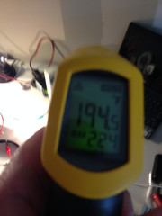
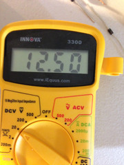
    The interesting thing here is I was getting more voltage out of the battery charger then was going into battery #3 next test is to measure current. also I got a lot of heat from the 20 watt bulb that I plan to try and tap into as well.


    -Altrez

    Comment


    • Torque Multiplier

      If you want a GREAT example of a torque multiplier to gain a MECHANICAL ADVANTAGE, take a look at this video.

      Replace the drill with a pulse motor that uses almost NOTHING in voltage and current to turn the shaft, and look at the work that is done at the other end. If you think there isn't any, stick your finger between a couple neos in attraction mode and then talk to me about the power there. Magnets that slide by each other, especially at speed, are so much easier to pull apart than when they are stuck together and you try to pull one straight back from the other. Anybody who has tried to separate two neos knows exactly what I am talking about.

      In this video you see the shaft driving two short stroke POWERFUL pistons, or rods. Now what could you attach to those rods? This is a variation of the GAP power device, but an improvement I believe.

      When I talk about a basic free energy device, I am talking about taking things we absolutely KNOW will work, principles we KNOW will work, and putting several of them together in working devices to achieve a desired outcome. This is just an example of combining a couple different things. I'm not saying I built one and it is THE answer. I just think we need to make sure we are not too narrow in our focus one ONE device, and we need a combination of the best of several things put together to get where we wanta go.

      https://www.youtube.com/watch?v=XdnSgH0Vvlw

      Dave
      Last edited by Turion; 10-28-2014, 06:42 PM.
      “Advances are made by answering questions. Discoveries are made by questioning answers.”
      —Bernhard Haisch, Astrophysicist

      Comment


      • I don't see a link to the Video.

        -Altrez

        Comment


        • Video link

          Oops
          https://www.youtube.com/watch?v=XdnSgH0Vvlw
          “Advances are made by answering questions. Discoveries are made by questioning answers.”
          —Bernhard Haisch, Astrophysicist

          Comment


          • That is pretty interesting.

            -Altrez

            Comment


            • I am working on conditioning all my battery's with my Bedini charger. Once I am done with that they will be the backbone of the Tesla switch. I have a thermoelectric module coming in tomorrow and parts to build the 20 watt regulated circuit.

              The first part for my build then will be done. After that I am thinking pulse motor.


              -Altrez

              Comment


              • magnetic field in motion

                Thanks for the video Dave, I questioned a while back about the field in motion, the general consensus was that , the field maintains its' intensity regardless of speed as long as proximity was maintained.?
                If you don't have a north field present ,its a south, but fields in motion change things.
                You can't have them too close.?
                Distance and angle are the key me thinks.
                artv

                Comment


                • I know you all understand that if we could turn the magnetism in a magnet off and on it would be freaking easy to build an electric motor, and also that if we can shield a magnet, we can build an electric motor. That's why there was so much interest in the You Tube videos of James Rodney and his stator:

                  https://www.youtube.com/watch?v=HiI2...cza5XxtHh-lM7Q

                  Well, yesterday I was doing some reading on how to put magnets together in a Halbach array, so one side has amplified field, and the other pole is eliminated. In other words, a magnet with a north pole, but no south, which would be perfect for building an electric motor. I read that refrigerator magnets are already set up this way One side sticks to the fridge and the other side is nonmagnetic. Obviously we have the technology to do that, so why so we need magnetic shielding? So I wondered if refrigerator magnets could be used to shield a neo. So I tried it.

                  The refrigerator magnet definitely reduces the magnetic pull of the neos SIGNIFICANTLY. The stuff I have is cheap and thin. I need the stuff they use to make magnetic signs for the sides of cars, which is nice and thick because I had to put three layers, which is about 1/2 inch thick. You are defeating the purpose when you add layers because one side is magnetic, so you are ADDING magnetic material, but it still worked. The more layers, the more it reduces it. With three layers ( 1/2 inch thick total) I could touch a screwdriver to the neo and pull it away without too much trouble. I was actually tap, tap, tapping it. Without it, it takes two hands to pry the screwdriver loose. I am going to do some tests today with a fish scale to measure foot pounds of torque required to pull a hinged pice of steel loose from a magnet held in my bench vise, and how that is reduced per layer of the shielding. I will shoot some video. There is a sign place here in town that might sell me some of the material for car signs.

                  Next I need to make a rotor and stator to try this out and see what kind of torque I can get. All these little things could add up to one big thing.

                  Dave
                  “Advances are made by answering questions. Discoveries are made by questioning answers.”
                  —Bernhard Haisch, Astrophysicist

                  Comment


                  • I knocked up a basic layout of Johns simple "lightbulb" diagram 3 battery switch. Used some 18650s I salvaged from a makita tool pack and a 1 watt LED. Charging battery charging nicely. Wondering if anyone has a schematic for a toggle switch so I dont have to physically remove each battery from its holder.

                    I thought I could use multiple switches and weld/solder a bar across each, so one throw could toggle multiple switches. Any ideas guys? DPDT? TPTT?

                    Regards
                    "Once you've come to the conclusion that what what you know already is all you need to know, then you have a degree in disinterest." - John Dobson

                    Comment


                    • Cheers Matt. I get confused easily when it comes to this. Dont really want anything automated (yet) would just like to toggle each battery through the circuit at the flick of the switch manually.

                      Will have a scribble with 6 x SP3Ts and see what I come up with.

                      Regards
                      "Once you've come to the conclusion that what what you know already is all you need to know, then you have a degree in disinterest." - John Dobson

                      Comment


                      • 12 volt switches

                        These are 12 volt switches:
                        MHS133: SP3T Slide Switch 0.3A 30V DC: Alcoswitch/Tyco Electronics

                        Ot here are some on eBay. DOn't know what voltage they are
                        On on on SP3T Toggle Switch 6 Amp M2033 | eBay
                        “Advances are made by answering questions. Discoveries are made by questioning answers.”
                        —Bernhard Haisch, Astrophysicist

                        Comment


                        • Originally posted by Matthew Jones
                          Each Pole of each battery only has a possible connection to 3 points so 6 SP3T switches would do it. That and a good ledger so you don't accidentally throw the wrong configuration.

                          Manual might be cheaper.

                          But then again if you want to spend money, use relays and a microprocessor with a separate power supply. Use the analog ports to switch and data log the voltages.

                          Matt
                          Thanks guys. Matt I just read your msg again and realize what you mean by "ledger". I think. Im guessing you mean a series of protocols by which one follows to make sure the correct procedure is followed. That, while possible, is not my intent, and Id rather swap batteries than do that. I was just trying to visualise a switch or arrangement of "linked" switches where the user can toggle a single throw between three modes. Each mode with the battery in a different position. Thus each battery gets a chance in each location. But I would only bother with this if it was setup so with a single toggle each "mode" was selected. And no timers or ICs. Just simple "mode 1/2/3" with a separate "off" perhaps. Even thought of making my own knife style switch to suit. Or maybe a rotating contactor. Needs to have a decent amp rating if scaled up, but those minis that Turion linked might work fine with this low power LED circuit.

                          I know its a minor thing. But it would make testing the light circuit nice and easy.

                          Regards
                          Last edited by ren; 10-30-2014, 10:10 AM.
                          "Once you've come to the conclusion that what what you know already is all you need to know, then you have a degree in disinterest." - John Dobson

                          Comment


                          • Gentlemen,

                            Check out this article:
                            https://gigaom.com/2014/10/29/a-batt...ors_picks=true

                            That's not TOO horribly far from you is it Matt?
                            “Advances are made by answering questions. Discoveries are made by questioning answers.”
                            —Bernhard Haisch, Astrophysicist

                            Comment


                            • Originally posted by Turion View Post
                              Gentlemen,

                              Check out this article:
                              https://gigaom.com/2014/10/29/a-batt...ors_picks=true

                              That's not TOO horribly far from you is it Matt?
                              Thats pretty interesting if true. I will keep an eye on it.


                              -Altrez

                              Comment


                              • Update:

                                I plan on updating my tesla switch config with a Pulse-width modulation setup to control the motor this weekend. I should have some hard data to post later this weekend on that expirment. My goal has been to make the Tesla Switch as efficient as possible so it can be used as the power source for the basic free energy device.

                                So far my batteries that have been condition with the Bedini charger are running longer than the ones that have not so that is already allowing me longer run times while using the tesla switch config.

                                It also allows for faster charging on the battery in the third position! My logic on this has been that if I can cut down the time it takes to charge the battery while at the same time having longer run times with conditioned batteries it should make a big difference in overall run times / output.

                                At the same time I have been running two off the shelf razor motors in a generator configuration at a gear ratio of 1-1 charging a 4th conditioned battery that will be added into the tesla switch once I see an overall voltage drop.

                                Now the switch is running longer than I can stay up to test it. The last thing I had to do is tap into the Tesla switch to run the next part of the build. For now I am running a small inverter from the battery located in the third position I have played with the loads and can run a small 13 watt cfl while battery 3 is charging. IMHO thats more then enough extra energy to run a pulse motor and charge yet another battery to do real work.

                                Sounds too simple I know but this is not just theory I have tested it. And will post pics data logging and a youtube video of the system working when I get a chance.


                                -Altrez

                                Comment

                                Working...
                                X