Announcement

Collapse
No announcement yet.

Newman Motor Finally Explained?

Collapse
X
 
  • Filter
  • Time
  • Show
Clear All
new posts

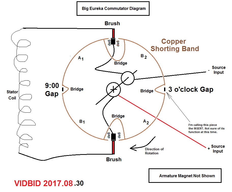
  • GAP solid state commutator

    Look at this "Hybrid Coil" commutator of mine with custom latching Reed Switches: Three channels: Pulse width, BEMF, and CEMF output; Powered by a 12 volt DC fan:

    A simple readjustment of the trigger magnets can turn my GAP commutator into a Joe Newman commutator like Miller's.
    Attached Files
    Last edited by Allen Burgess; 08-31-2017, 09:01 PM.

    Comment


    • Geoffry S. Miller.

      @Vidbid,

      What did Miller's commutator hook up to? The center contact looks like it might correspond to Art's Porter's proportions?

      Comment


      • Miller

        Originally posted by Allen Burgess View Post
        @Vidbid,

        What did Miller's commutator hook up to? The center contact looks like it might correspond to Art's Porter's proportions?
        I'm a fan of Art Porter of Gap Power.

        GAP Power, Magnetic Neutralization

        https://www.youtube.com/watch?v=u8eZ3YsT8nI

        I believe his machines possess overunity capabilities.

        However, to me, it's like comparing apples to oranges.

        In my view, Newman's latest commutator is super simple.

        Miller is a good guy. I have a lot of respect for him.


        Notice that his build (the above prototype) lacks Newman's "Copper Shorting Band" so-termed by me.

        In the above build, the commutator speed is controlled by an external secondary motor.

        However, I'm a traditionalist and a purist, so I like sticking to Newman's design.

        The two small discs supply source power.

        The singular large disc alternately supplies power to the stator coil.

        There you have it.

        Sidebar: I, too, am very much interested in upping the rotational speed of the Newman motor, hence, the interest in magnet bearings.
        Last edited by vidbid; 02-15-2019, 05:54 AM.
        Regards,

        VIDBID

        Comment


        • Commutator

          Originally posted by maxc View Post
          With this commutator I can short the coil out but I noticed that pulls 20 more percent power and slows it down. I order 10 more pounds of wire and I have some high frequency transformer laminates. I'm going to remove the magnet rotor and use a laminate rotor. To beat lenz's law. Also I'm going to put the laminates in the coils.
          This is an interesting commutator setup.
          I'm just curious, did you include all three segments described by Newman (referring to the FIRE, BLANK, and SHORT segments described in Chapter 9 of his book)?

          pjotterkjen

          Comment


          • Disc design

            Originally posted by vidbid View Post
            The video is still available:

            Code:
            https://www.youtube.com/watch?v=sZ2-p5Zc8qY
            And that image is still there, but blurry:


            Anyhow, here's his famous commutator:

            Notice how every third section of the commutator shorts the stator coil.


            Rest in Peace: Joseph Westley Newman (July 2, 1936 – March 6, 2015)

            By the way, everybody, you can get his writings from the following link:

            http://www.free-energy-info.tuks.nl/BooksDownload.html
            Vidbid,
            I'm now trying to decide which disc type wound work best or at all. My disc is only 3+ inches wide by 1/2" thick. Not a good flywheel at all. But I want to use the "firing, blank, shorting," segments on the disc design. My segments will not be as small or as many as this picture shows.

            I have built the barrel type comm but no shorting segments on it. I followed the design from the complete display that part of is shown above(top).

            wantomake

            Comment


            • Capacitor and spark gap?

              Originally posted by vidbid View Post
              Thanks. Much appreciated.


              wantomake,

              Good points and interesting.

              I want to say about the idea of using reed switches. Personally, I don't believe it's a Newman motor if it's using reed switches.

              About the BEMF or CEMF, to me, that's the gold in the machine.

              To me, the magic happens in the commutator. If you look at Newman's latest videos, take some time and study his commutator.


              It looks like Newman has a "continuous" shorted band on his commutator, which I'll be implementing in my commutator design.

              For the purposes of constructing a Newman commutator, I have a couple of steel discs that I'm playing with, but I'm thinking about using copper, instead, but I might just use one of the steel discs to prototype with.

              I think the majority of people miss the importance of Newman's commutator in the design, and I'm not talking about his book. I believe people need to really watch his last few videos of his motor Big Eureka.

              It's really a shame that he didn't explain its workings while he was alive.

              Luckily, I think there's enough video segments of its operation that we can piece its construction together.

              I believe the most important component in his motor is the commutator, especially, the commutator in Big Eureka.

              I believe that's where our attention needs to be.
              Hey vidbid,
              Could you add a capacitor with a spark gap(at top or bottom) across the coil?

              A spark gap is the only way to keep the capacitor from shorting out if connected across the coil.

              What do you think?.

              wantomake

              Comment


              • To all newman motor update from energybat labs 2017

                To All

                Geoffrey miller from energybat.com

                If you go to Aaron's website and buy my talk about
                the Joe Newman's Motor of this years Conference
                you will have a lot Questions answered.

                Have a great day.

                Geoffrey

                PS thanks Tom C.


                Originally posted by vidbid View Post
                I'm a fan of Art Porter of Gap Power.

                GAP Power, Magnetic Neutralization

                https://www.youtube.com/watch?v=u8eZ3YsT8nI

                I believe his machines possess overunity capabilities.

                However, to me, it's like comparing apples to oranges.

                In my view, Newman's latest commutator is super simple.

                Miller is a good guy. I have a lot of respect for him.


                Notice that his build (the above prototype) lacks Newman's "Copper Shorting Band" so-termed by me.

                In the above build, the commutator speed is controlled by an external secondary motor.

                However, I'm a traditionalist and a purist, so I like sticking to Newman's design.

                The two small discs supply source power.

                The singular large disc alternately supplies power to the stator coil.

                There you have it.

                Sidebar: I, too, am very much interested in upping the rotational speed of the Newman motor, hence, the interest in magnet bearings.

                Comment


                • Originally posted by wantomake View Post
                  Vidbid,
                  I'm now trying to decide which disc type wound work best or at all. My disc is only 3+ inches wide by 1/2" thick. Not a good flywheel at all. But I want to use the "firing, blank, shorting," segments on the disc design. My segments will not be as small or as many as this picture shows.

                  I have built the barrel type comm but no shorting segments on it. I followed the design from the complete display that part of is shown above(top).

                  wantomake
                  Those designs are obsolete. Newman changed how he designed the commutator. Look at the commutator on Big Eureka. That is Newman's latest design.
                  Last edited by vidbid; 08-30-2017, 07:13 PM.
                  Regards,

                  VIDBID

                  Comment


                  • Originally posted by wantomake
                    Geoffrey,
                    I did purchase the presentation from the conference and you didn't spend enough time on build details. I may have missed something but I'll look at it again.

                    wantomake
                    Have you watched the Newman Movie that came out in 2016?
                    Regards,

                    VIDBID

                    Comment


                    • Evidence for the 9 O'Clock Gap

                      Originally posted by vidbid View Post

                      Newman Motor Commutator Contact on Large Disc Circumference


                      Newman Motor Commutator3 O'clock Gap on Large Disc Circumference


                      Possible Schematic or Diagram for Newman Motor Commutator

                      @wantomake, Thanks.

                      Let me start out by saying, to me, the first thing of importance is to make the observation.

                      That's what I do. I observe, and then I try to make an observation.

                      After I make the observation, then I will attempt to formulate a theory.

                      I'm not sure what the function of the 3 O'clock Gap is, but I do observe that there is clearly a 3 O'clock Gap there.

                      As for the 9 O'clock Gap, I'm only speculating that it exists. I don't know for certain that it is there, but I can speculate that if it is there, what then how it might affect the operation of the commutator.

                      As for the bridges across the commutator contacts, again, that is only speculation. At this point, I can only speculate.

                      I'm pretty sure that Newman was feeding the fly-back from his coil into his battery at some point. I believe (but I can't prove) that the function of the caps is to catch the fly-back in some way and hold it, possibly, as a buffer.

                      In one of his videos (I'm not sure which), Newman stated something about keeping the magnetic field in the coil (at least, that's what I believe that I heard.) Would his latest commutator design accomplish that? I believe the answer is Possibly.

                      Good luck to all who attempt any kind of replication based on Newman's latest work.

                      At this point, I believe Newman's latest motor works and produces overunity. I believe that the answer has got to be simple. I'm not worried about the Einsteinian theory that Newman embraced and tried to explain. He would have done better just to show how he built the machine, but he didn't with his latest machine.

                      So we have to piece it together with his videos and images of his latest machine.
                      I found this image that shows the so-called 9 O'Clock Gap

                      https://pesn.com/archive/2010/06/30/...o/img_0093.jpg

                      So, I'll have to update my diagram.
                      Regards,

                      VIDBID

                      Comment


                      • Saw it.

                        Originally posted by vidbid View Post
                        Have you watched the Newman Movie that came out in 2016?
                        Vidbid,
                        Yes I watched it and it just infuriated me even more against those suppressive bastards that are killing and destroying the only mother earth we live on. For what? For greed and power over us.

                        wantomake

                        Comment


                        • Art Porter and Joe Newman commutator contrast.

                          Compare the proportions between Art's scope shot and Joe's commutator ratios below far right: The center photo is Art's semi circular opti-cutter commutator on the far end. 9/16 to 3/16 = 54% and 18% while Art's scope shot reveals 43% and 18%. Joe's blank space equals Art's BEMF space exactly following the power pulse! Very interesting.

                          Joe is obviously sleeping his BEMF, so any feedback to source has to come from the short section of his commutator:

                          Both magnet coil and commutator setups qualify as "Hybrid Input, Output" coils. Joe's rotational segment only catches 1/8th of the power coil for output unlike Art's 38% from the direct linear alignment of his oscillator magnet piston.
                          Attached Files
                          Last edited by Allen Burgess; 08-31-2017, 09:00 PM.

                          Comment


                          • Originally posted by wantomake View Post
                            Vidbid,
                            Yes I watched it and it just infuriated me even more against those suppressive bastards that are killing and destroying the only mother earth we live on. For what? For greed and power over us.

                            wantomake
                            It's about control.
                            Regards,

                            VIDBID

                            Comment


                            • Originally posted by Allen Burgess View Post
                              Compare the proportions between Art's scope shot and Joe's commutator ratios below far right: The center photo is Art's semi circular opti-cutter commutator. 9/16 to 3/16 = 54% and 18% while Art's scope shot reveals 43% and 18%. Joe's blank space equals Art's BEMF space exactly following the power pulse! Very interesting.

                              Joe is obviously sleeping his BEMF, so any feedback to source has to come from the short section of his commutator:

                              Both magnet coil and commutator setups qualify as "Hybrid Input, Output" coils. Joe's rotational segment only catches 1/8th of the power coil for output unlike Art's 38% from the direct linear alignment of his oscillator magnet piston.
                              Joe is obviously sleeping his BEMF

                              I like that expression. I'm not sure I know what it means.

                              I suppose it could mean that the charge in the coil is being conserved.


                              Interesting.
                              Last edited by vidbid; 02-15-2019, 05:57 AM.
                              Regards,

                              VIDBID

                              Comment


                              • Originally posted by vidbid View Post
                                Joe is obviously sleeping his BEMF

                                I like that expression. I'm not sure I know what it means.

                                I suppose it could mean that the charge in the coil is being conserved.

                                Interesting.
                                Yes, it sure is!
                                In my understanding from what is written in the book, the BLANK allows no current to COMPLETE the circuit and thus prevents the current to go back to the input voltage source (all those tiny batteries in series). This prevents the batteries from draining quickly. So, only high voltage pressure is used, and a very short input current as a consequence (but only into the coil). This causes a magnetic field to build quickly, and in the BLANK segment, this field collapses which causes a current TRYING to flow to keep the magnetic field at the same strength. This in turn turns the magnet with a higher force WITHOUT using (draining) the battery.
                                Then the SHORT segment is there to EXTEND the current flowing, and this lets the magnet rotor turn with an even greater force. Batteries gets part of the BEMF through the commutator and are charged that way.
                                Timing of these segments is extremely important and Newman says each build has his own tuning or exact timing of these segments with respect to the position of the magnet rotor.

                                Then the Eureka communtator. This one keeps me puzzling. How did Newman go from the multi segment commutator to the big one with only four copper segments? And, were they interconnected as you think they are?
                                Geoffrey talks a little bit about it in his presentation. It starts at 51:38. Can anybody tell me what it means when he says "you put a 45 here and a 45 here (on the other side)"? Is he referring to the position of the brushes? Because the small commutator is covered with a complete ring of copper.
                                Then he says: "you go from 12 to 3 o'clock with a copper strip, and from 6 to 9 o'clock with another strip of copper. Then you connect the small copper ring on the front to one of the strips, and the small copper ring on the back gets connected to the other copper strip. And that's it."
                                So vidbid, you may want to listen to this, and I guess you will make some adjustments in your design accordingly.
                                Q: were the other segments (assuming there were four) connected to something? Interesting question. Geoffrey does not answer that one, so maybe he can here? Were they maybe used to flip the voltage polarity, as in the older commutator with the many segments?
                                Anyways, to my understanding, if Geoffrey is telling the truth, you need to remove the bridges, and connect either A1-A2 or B1-B2 to the small copper rings, as indicated by Geoffrey in the video.
                                This would allow for me to understand how the big machine can start on it's own. Connecting the voltage in the position where the voltage is applied to the coil would generate the magnetic field, hence a big torque on the magnet rotor through the interaction of the coils's electromagnetic field with the magnetic field of the magnets.
                                Of course, you will need to add in the big capacitors in your design to suppress the BEMF spike. Seems important to me.

                                Geoffrey further states in his presentation (a bit before the above mentioned description of the big commutator) that any build that presents an electronic way of pulsing cannot be a Newman motor. He says you need the commutator. I wonder if that is true and I'm planning to find out when I have the 15-C2 (Ch. 6 book) or 22-K1 (p. 67 book) on my bench and getting ready to replace the mechanical (moving) parts with an electronic version.
                                That is going to be a wonderful journey. I think the combination of Bedini's electronic inventions and Newman inventions together with Babcock's switching technology could well produce an highly efficient small home unit that produces enough energy for daily use, without having to use huge amounts of pounds of wire or lots of PV panels on my roof.

                                If only they could have gathered together, like the three musketeers, they would have had so much breakthrough power. So now, it's up to us, develop the thing and make it all open source so everybody can build one for his own use.

                                Can't wait to get going.

                                pjotterkjen
                                Last edited by pjotterkjen; 08-31-2017, 02:56 PM. Reason: adding comment

                                Comment

                                Working...
                                X