Announcement

Collapse
No announcement yet.

Re-Inventing The Wheel-Part1-Clemente_Figuera

Collapse
X
 
  • Filter
  • Time
  • Show
Clear All
new posts

  • A Quick drawing about Citfta's Part G

    Hello to All,

    Guess you all would be lost without my graphics...

    Here is a quick drawing of Citfta's Part G:


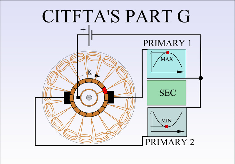
    OK, now you guys must realize that all coils in the armature of a Universal Motor (like in any other brushed motor) are "typically" OVERLAPPED, and not like represented on diagram above, I did it like that for purposes of clarity in the whole graphic.

    Whole Armature is contained within the black circle.

    On the center the gold smaller ring is the CONTINUOUS SLIP RING, where the Small Positive Brush is connected to Source Positive.

    We could see a gold wire running from Slip Ring to just ONE ELEMENT of the Commutator, that I painted RED with a + sign within.

    Commutator is based on a 16 elements as in Figuera's Patent from 1908, brushes are contacting Two Elements as also directed by Figuera, not allowing Field to Collapse.

    Say we are rotating whole armature in a CW direction or as represented by "R"...Then, Primary 1 would start the short period of MAX ENERGIZING, while Primary 2 would be at it LOWEST ENERGIZING...
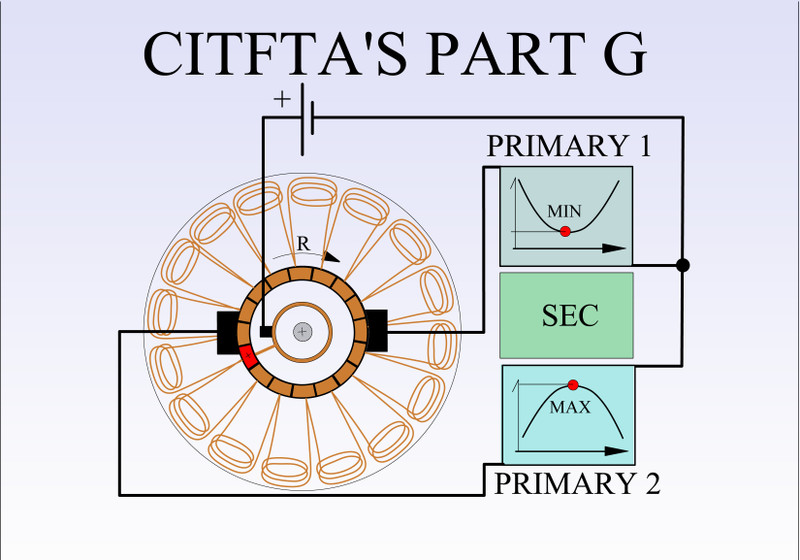
    Advancing rotation 180º then the opposite will take effect, like seen below:


    Hope is clearer now.


    Regards


    Ufopolitics
    Last edited by Ufopolitics; 09-02-2018, 07:42 PM.
    Principles for the Development of a Complete Mind: Study the science of art. Study the art of science. Develop your senses- especially learn how to see. Realize that everything connects to everything else.― Leonardo da Vinci

    Comment


    • Hello Bi and Ufo,

      Yes Bi, as Ufo has posted that is the correct way I have modified the motor. That was only an idea to test to see if I thought it might work in place of building a part G from scratch. I think it would probably be improved by rewinding the armature to more conform to the original configuration Figuera used. But even if you rewound the armature that would still be much easier than starting from scratch I think.

      I am curious as to what you might think could be an issue with this. My testing so far has shown that it does in fact produce an alternating rough sine wave with 180 degree phase difference. There probably needs to be another inductor in series with the input power lead in order to reduce some of the spiking seen in my scope shots. The idea Ufo suggested of using the existing field windings as individual inductors for each primary coil may be the solution for the spiky signal. Although I am not so sure the spikes are even a problem because when I load down the secondary the secondary signal shows no spikes.

      I like my modified motor because it lends itself so well to a lot of different experimental ideas. One idea I tried yesterday was to short out each of the field coils by just connecting the leads together. What really surprised me was that when both field coils were shorted the output went up slightly more than double what it was when the coils were just idly sitting there. And as far as I could tell without connecting some good meters the input power to the slip ring did not go up at all. And the input power to my driving motor did not go up either. Unfortunately before I could continue working and studying on this result I had to stop and go help my son on some projects.

      Later,
      Carroll
      Just because someone disagrees with you does NOT make them your enemy. We can disagree without attacking someone.

      Comment


      • Modded arm partG

        Originally posted by Ufopolitics View Post
        ...which travels through armature via one wire.
        ...
        I don't think so.

        Hi Ufo,


        Referring to figure (b), as you say "Citfta sends the source positive through a wire from slip ring to just one element of commutator...", which could be at 12 o'clock or where the blue arrow is. There are two paths for the current to flow in the armature from that comm bar; thru coils a & i to brush at 3 o'clock, and thru coils b & c to brush at 9 o'clock. Each brush is connected to opposite ends of the primary coil assembly.

        So there are at least two armature current paths resulting from citfta's mod. And that is desired; 2 paths, like partG should have. My concern is the third path* thru the modded armature, thru coils d, e, f, g, and h, from brush to brush. The two brushes will have differing potential or voltage except at one or two positions per revolution, so current will flow in this third path. How will this affect the output voltage function?

        To stop current in this third path, I wonder about cutting coil f. Easy enough to try I guess.

        I see citfta and Ufo have posted while I've been composing this (and doing laundry). So I'll put this up and address some other items after I study what those guys say.

        Regards,

        bi

        {edit} * third path. Member seaad has posted a diagram depicting the 3 paths. I added it here for clarity. Thanks seaad. Also thanks to Ufopolitics for his excellent graphics.
        Last edited by bistander; 09-03-2018, 01:12 PM. Reason: Added diagram

        Comment


        • Originally posted by citfta View Post
          Hi Dwane,

          I am not sure what you mean. The picture of my modified motor connected to the MY scooter motor is still there in post number 2781 of this thread.

          Carroll
          Hi citfta,
          My apologies, I have had a bad weekend. Things are a bit clearer today. I have confused this with something else I think.

          Anyway, I personally appreciate the contribution you have made to my understanding on this device.

          Regards

          Dwane

          Comment


          • Series Stator Coils added...

            Hello Bistander,

            Yes, I understand your concern...however, a good way to see this is by considering one brush would be "more positive" than the other when is nearer or contacting the directly positive element, which makes other brush to be "less positive" or "more negative"...understand?...but you've said that : "potential difference".

            Anyways wanted to add more material to your thinking (hoping not stressing your laundry...)

            Take a look at below image:


            Now you are very familiar how these motors work...but I will add some details:

            When these motors run with DC, their brushes are fixed positive and negative, or could be a Positive PWM, to obtain a constant speed...When running on AC, brushes swap polarity at cycles, BUT ALSO the Stator Fields, reason why they run on both currents.

            However on Citfta's Design as above, adding the two stator coils in series to each brush, brushes ALTERNATE POTENTIALS between Hi-Lo Positives, AS WELL as Stator Coils...and in my "rough" opinion about this circuit...

            I believe by using this diagram-circuit, we would be switching the interacting flux from one half of the stator to the other...which is all about same flux...just displacing through air gap at high RPM's.

            Do you think motor-controller above should run?, lousy but move in order to "assist" prime mover?

            I understand it is all about getting the right polarizations and timing...etc,etc.


            Regards, and hope you had finished your laundry by now.


            Ufopolitics

            EDIT: OH!!...Almost forget!!!...What about Generation of Energy (to Figuera's Primaries) from above design when rotated by prime mover?...I could also keep going by adding a small magnet to one of the armature bars...to act as magnetic reminiscence...plus a Capacitor instead of a battery, etc,etc...

            Anyways, All this... I want to TEST in a near future...only way to find out the correct answers.
            Last edited by Ufopolitics; 09-02-2018, 11:44 PM.
            Principles for the Development of a Complete Mind: Study the science of art. Study the art of science. Develop your senses- especially learn how to see. Realize that everything connects to everything else.― Leonardo da Vinci

            Comment


            • Originally posted by citfta View Post
              Hello Bi and Ufo,

              I like my modified motor because it lends itself so well to a lot of different experimental ideas. One idea I tried yesterday was to short out each of the field coils by just connecting the leads together. What really surprised me was that when both field coils were shorted the output went up slightly more than double what it was when the coils were just idly sitting there. And as far as I could tell without connecting some good meters the input power to the slip ring did not go up at all. And the input power to my driving motor did not go up either. Unfortunately before I could continue working and studying on this result I had to stop and go help my son on some projects.

              Later,
              Carroll
              Hello Citfta,

              I like it too...and yes, there are way more possibilities to enhance and test...

              Your result above, just by shorting stator coils (or field coils) were beyond ANY simple explanation!!

              Just need to find a good starting universal motor to work with...and yes, I will eventually look for one easier to take off winding (that is NOT SOAKED IN RESIN) and redoing it according to our requirements.


              Regards


              Ufopolitics
              Principles for the Development of a Complete Mind: Study the science of art. Study the art of science. Develop your senses- especially learn how to see. Realize that everything connects to everything else.― Leonardo da Vinci

              Comment


              • Field coils on partG

                Originally posted by Ufopolitics View Post
                ...

                Take a look at below image:


                Now you are very familiar how these motors work...but I will add some details:

                When these motors run with DC, their brushes are fixed positive and negative, or could be a Positive PWM, to obtain a constant speed...When running on AC, brushes swap polarity at cycles, BUT ALSO the Stator Fields, reason why they run on both currents.

                However on Citfta's Design as above, adding the two stator coils in series to each brush, brushes ALTERNATE POTENTIALS between Hi-Lo Positives, AS WELL as Stator Coils...and in my "rough" opinion about this circuit...

                I believe by using this diagram-circuit, we would be switching the interacting flux from one half of the stator to the other...which is all about same flux...just displacing through air gap at high RPM's.

                Do you think motor-controller above should run?, lousy but move in order to "assist" prime mover?
                ...
                Hi Ufo,

                I don't think it'll work well to energize field coils (or use PM field) on an armature modded to run as partG. Doing so will generate voltage and "extra" current in the primary coils not consistent with the tone of Figuera, and cause shaft torque and load current in the prime mover of partG which is intolerable IMO. The steel poles in the stator complete the magnetic circuit around the armature so contribute to high inductance in the armature coils, which you want.

                I think for a good partG you need high inductance and low resistance. When citfta shorted his stator coils he likely effectively increased the reactance of the armature coils giving him a favorable outcome.

                There may be a mechanical means to increase the inductance of this modded arm partG. Motors run the stator and armature fields in quadrature. Since our machine doesn't use the stator field, the steel structure position isn't critical for field interaction. A reposition could significantly reduce reluctance in the modded armature magnetic circuit which then will increase inductance of the coils. To easily test this, simply rotate the brush holder plate 90° (for 2-pole machine).

                FWIW, I can't envision a re-wind being helpful at this stage of development.

                Regards,

                bi

                Comment


                • Part G different principles

                  https://vimeo.com/178144785
                  Attached Files
                  Last edited by seaad; 09-03-2018, 10:49 AM.

                  Comment


                  • Hi Guys,
                    I have been wondering about the efficiency of the armature field coils. Using uniform fields in the armature might not be giving us a maximum definition of flux at the primary coils. I also wondered if they need to be rewound so as to reflect the change in induction possible anticipated by Clemente. The object that keeps springing to my mind is the notion that what Clemente specifically wanted was a change in field strength that deliberately forces a gradual structural change to the magnetic flux created. That is, the "G" rotor is where all the action is. The field coils of the primary are all fixed, whether there is one coil or 20 coils. The flux coming from the "G" rotor is what creates the field dynamic. I hope I have made myself clear.

                    My Washing machine motor is in the post!

                    Regards

                    Dwane
                    Last edited by Dwane; 09-03-2018, 11:52 AM.

                    Comment


                    • Free Energy Universal Motor...

                      Ok Guys...

                      For those who already got your Universal Motor to build the Citfta's Part G...but still waiting on more parts...in the meantime...you could put together this awesome project to demonstrate free energy and Motion Perpetual Machines are out there BUT BASICALLY

                      VERY SIMPLE TO BUILD...

                      Bistander and Citfta I know you will not just walk, but run to build this one:

                      [VIDEO]https://m.youtube.com/watch?v=QWXQ9eagfc0#[/VIDEO]

                      All you need is some wood, a small DC Motor...a 9V Battery...and YES, a plastic welder gun...to glue the heck out of all...oh! and a soldering gun.


                      Regards


                      Ufopolitics
                      Last edited by Ufopolitics; 09-05-2018, 03:39 PM.
                      Principles for the Development of a Complete Mind: Study the science of art. Study the art of science. Develop your senses- especially learn how to see. Realize that everything connects to everything else.― Leonardo da Vinci

                      Comment


                      • To succeed you'll need that music in the background also!
                        Regards Arne

                        Comment


                        • Originally posted by seaad View Post
                          To succeed you'll need that music in the background also!
                          Regards Arne
                          DEFINITIVELY so!
                          Principles for the Development of a Complete Mind: Study the science of art. Study the art of science. Develop your senses- especially learn how to see. Realize that everything connects to everything else.― Leonardo da Vinci

                          Comment


                          • Hi Arne,

                            I think you missed a couple of very important parts of the video. First you obviously must leave your soldering pencil as nasty as possible so you can get those special solder connections. Then you must connect that bridge rectifier with the AC side going to the field coils and the DC side going to the armature windings. That is probably the most important secret in the video. I mean if that doesn't convince you that guy knows what he is doing, what would it take to convince you? And then the last thing I saw was that you have to leave the 9 volt battery connected until he can turn on the hidden switch. Just connecting the battery until the motor gets up to speed is not good enough.

                            Thanks UFO for a good laugh.

                            Carroll
                            Just because someone disagrees with you does NOT make them your enemy. We can disagree without attacking someone.

                            Comment


                            • Originally posted by citfta View Post
                              Hi Arne,

                              I think you missed a couple of very important parts of the video. First you obviously must leave your soldering pencil as nasty as possible so you can get those special solder connections. Then you must connect that bridge rectifier with the AC side going to the field coils and the DC side going to the armature windings. That is probably the most important secret in the video. I mean if that doesn't convince you that guy knows what he is doing, what would it take to convince you?

                              Carroll
                              Hi Citfta,

                              Sorry but I highly disagree about important details (on video) that must be accomplished when putting it together...

                              Did you notice when Generating Universal Motor gets front pulley-plastic fan attached to its shaft?

                              Well...that's ONE MAIN KEY there!!

                              Notice how much that front Wheel-assy WOBBLES?
                              It is DEFINITIVELY an UNBALANCED FLYWHEEL!!!
                              IMHO if that frt wheel is balanced...it simply won't work!!

                              Hope you could reproduce it AS IS on Video.

                              Finally...see how wrong you were about YouTube??!!


                              Regards


                              Ufopolitics
                              Principles for the Development of a Complete Mind: Study the science of art. Study the art of science. Develop your senses- especially learn how to see. Realize that everything connects to everything else.― Leonardo da Vinci

                              Comment


                              • Sorry

                                I am sorry to have to disappoint you UFO. But I have only been soldering for a little over 50 years so my soldering skills are just not up to the level presented in the video. My replication would surely be a failure.

                                I did notice after watching again that we may have both missed another key feature. The armature is very loose in the stator housing causing some very high flux leakage. Maybe that is the real key to success.

                                Carroll
                                Just because someone disagrees with you does NOT make them your enemy. We can disagree without attacking someone.

                                Comment

                                Working...
                                X