Announcement

Collapse
No announcement yet.

Re-Inventing The Wheel-Part1-Clemente_Figuera

Collapse
X
 
  • Filter
  • Time
  • Show
Clear All
new posts

  • Originally posted by Ufopolitics View Post

    ... although I wanted to make a final test and that is to connect the Inverter output to mechanical switch running to do the make-brake (hopefully within the right sync, have to monitor wave at scope) then see if amp draw at input decreases, if it does, then we do need the make-brake included in our waves...
    It worked out as reducing amps considerably, EMF Induction there as well, but switch started arcing a lot, and no way to sync both, so stopped testing.

    Must admit it was a crazy test!!...switch is designed to work with DC Input, not AC, not even the mod wave...

    End of electronic wave testing, back to mechanical driving.


    Regards


    Ufopolitics
    Last edited by Ufopolitics; 10-31-2017, 03:00 PM.
    Principles for the Development of a Complete Mind: Study the science of art. Study the art of science. Develop your senses- especially learn how to see. Realize that everything connects to everything else.― Leonardo da Vinci

    Comment


    • Power In Power Out

      Hi UFO,

      It would be interesting to see if the inner coil output (the one you run the electric drill from), when rectified and smoothed is actually producing something close to 165W DC for 100W DC input.

      Regards

      L192

      Comment


      • New Meters for future tests...

        Hello All,

        I have ordered Four of the Meters that Luc is using to run the 3 batt testings(thanks Luc for providing the links!!), as I find them awesome!...they reduce enormous space PLUS we have at least TWO Meters in one reading Amps and Voltage plus doing the Math on Wattage...excellent for Videos since will take very reduced space on the screen

        I ordered Two DC:

        DC 20A-100V

        And Two AC:

        AC 200A METER

        They should be here by Tuesday, next week.

        Got a kind of silly question......speaking about Wattage...is there AC and DC Wattage?...In other words, if we have AC Volts and AC Amps Watts...is that anyway comparable to DC Amps and DC Volts Watts?

        I know the "standard procedure", where in order to establish the proper readings for comparison in these cases, ALL PARAMETERS MUST BE in the SAME levels, meaning, ALL either DC or ALL AC...but somehow this question arise and just wanted to clear my doubts.


        Regards


        Ufopolitics
        Last edited by Ufopolitics; 11-02-2017, 01:18 PM.
        Principles for the Development of a Complete Mind: Study the science of art. Study the art of science. Develop your senses- especially learn how to see. Realize that everything connects to everything else.― Leonardo da Vinci

        Comment


        • AC power

          Originally posted by Ufopolitics View Post
          ...

          Got a kind of silly question......speaking about Wattage...is there AC and DC Wattage?...In other words, if we have AC Volts and AC Amps Watts...is that anyway comparable to DC Amps and DC Volts Watts?

          I know the "standard procedure", where in order to establish the proper readings for comparison in these cases, ALL PARAMETERS MUST BE in the SAME levels, meaning, ALL either DC or ALL AC...but somehow this question arise and just wanted to clear my doubt.
          Hi Ufo,

          AC power can be complex (pun intended). Wikipedia does decent explanation. Has to be loads of other sites and texts covering this subject.

          https://en.m.wikipedia.org/wiki/AC_power

          Regards,

          bi

          Comment


          • Originally posted by bistander View Post
            Hi Ufo,

            AC power can be complex (pun intended).
            Auch......

            Hey, thanks Bistander!!...


            Originally posted by bistander View Post
            Wikipedia does decent explanation. Has to be loads of other sites and texts covering this subject.

            https://en.m.wikipedia.org/wiki/AC_power

            Regards,

            bi
            Thanks, indeed complex subject on AC Power (or AC Watts?!...)

            I went over article (lightly) as can see it is basically dependent on the load types which would change the power response as to V & A reactions.

            So, that is one main reason why we should do it on DC Power for this type of comparisons I believe...

            Anyways, since I don't have a problem in measuring ALL in DC...It is perfectly ok with me.

            Thanks for the answer Bistander!

            Regards


            Ufopolitics
            Principles for the Development of a Complete Mind: Study the science of art. Study the art of science. Develop your senses- especially learn how to see. Realize that everything connects to everything else.― Leonardo da Vinci

            Comment


            • More about driver build (brushes)

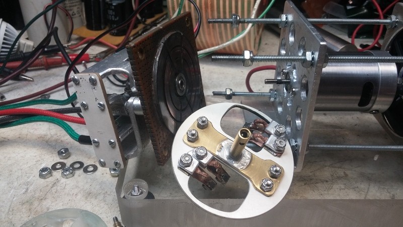
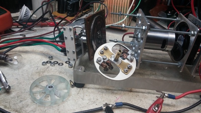
              Here, a couple of pics from driver showing the brushes:


              It is already finished and running beautifully, these pics were from before, when taken apart to install inner nylon adjustment nuts for the copper arcs segments board.


              Regards


              Ufopolitics
              Principles for the Development of a Complete Mind: Study the science of art. Study the art of science. Develop your senses- especially learn how to see. Realize that everything connects to everything else.― Leonardo da Vinci

              Comment


              • AC Power measurement

                Hi UFO,

                If you have a pure sine wave then a decent RMS reading digital multimeter can be used to measure AC Volts and Amps and calculate output power for comparison with input power.
                If the waveform is other than a pure sine, then most reliable method is to rectify and smooth for clean DC and then measure with multimeter DC V & A.

                I have a digital scope with a math function that can process complex voltage and current waveforms and provide an average power measurement, but even then I would still check using the DC method if I appeared to be getting an OU indication.

                In my experience most results that indicate OU are disappointingly not, after rechecking using the DC method.

                Regards

                L192

                Comment


                • Originally posted by Listener192 View Post
                  Hi UFO,

                  If you have a pure sine wave then a decent RMS reading digital multimeter can be used to measure AC Volts and Amps and calculate output power for comparison with input power.
                  If the waveform is other than a pure sine, then most reliable method is to rectify and smooth for clean DC and then measure with multimeter DC V & A.

                  I have a digital scope with a math function that can process complex voltage and current waveforms and provide an average power measurement, but even then I would still check using the DC method if I appeared to be getting an OU indication.

                  In my experience most results that indicate OU are disappointingly not, after rechecking using the DC method.

                  Regards

                  L192
                  Thanks L192!

                  Yeah, I got it...and so I will do all checks with DC rectified output.

                  I don't have a pure sine AC wave at Output, I have more like a Modified Wave, (same as Exciter Generates) still it runs any appliance same way an inverter with mod-sine does.

                  A Typical Rotary, Two Parts Generator does a smoother and so called "pure" sine, just because of what Figuera analyzes (observes) on the first part of his 1908 patent...which bolts down to the "Approach and Leave" from the Max EMF Induction POINT, as We could consider it also as the center PEAKS, which takes place at positive and negative peaks of a full cycle "pure" sine.

                  Other words, the rotating exciter (basically the Magnetic Field) approaching and leaving the way it does, generates the smooth, pure design. Also considering that Exciter Field is always ON, never turns off, so there are no abrupt Field Collapses at all.

                  In our case we are generating a wave based on the same principle, except "Approach and Leave" process are done by Field collapses to then reverse polarities on a Static Exciter Coil, therefore, it would be impossible that just out of the wires terminals from Output Coils we will obtain a pure, smooth Sinewave.

                  We all know there are some Power Inverters which deliver a pure sinewave, and so they are way more expensive because of that property, however, this tells Us that it could be done...to "purify" the sinewave from a mod to a smoother one WITHOUT ROTATION, just solid state...don't know if it would be even worth it to make that happen in our case...since a modified sine runs every single tool or appliance out there same way the cheaper, mod-sine do.

                  However, some sophisticated electronic equipment will run better on smooth, pure siewave...found this article which is pretty good:

                  Pure Sine wave Versus Modified Sine wave, what's the difference?

                  Regards


                  Ufopolitics
                  Last edited by Ufopolitics; 11-02-2017, 09:25 PM.
                  Principles for the Development of a Complete Mind: Study the science of art. Study the art of science. Develop your senses- especially learn how to see. Realize that everything connects to everything else.― Leonardo da Vinci

                  Comment


                  • AC power measurement

                    Hi UFO,

                    A second issue with AC power measurement comes about when you measure the power into an inductive load. When using a resistive load, the AC voltage and Current waveforms are in phase and the power measured is the real power dissipated in the load.

                    In the inductive load case, the voltage and current get out of phase due to part of the energy being stored in the inductive load, then returning to the generating source. Now the power consists of a real power (power used component) and a reactive power component (power returned to the source)component. Reactive power is expressed as VAR (Reactive Volt Amperes).

                    Complex power or apparent power is expressed as VA (Volt Amperes) and is the combination of real power and reactive power.

                    The ratio between real and reactive power is expressed as PF (Power Factor). The range for PF is -1 to 1.

                    So to measure real power into an inductive load such as an AC drill, where the voltage waveform is a square wave with little spikes, is very difficult without a digital scope with V x A math function and a current clamp.

                    Regards

                    L192

                    Comment


                    • Originally posted by Listener192 View Post
                      Hi UFO,

                      A second issue with AC power measurement comes about when you measure the power into an inductive load. When using a resistive load, the AC voltage and Current waveforms are in phase and the power measured is the real power dissipated in the load.

                      In the inductive load case, the voltage and current get out of phase due to part of the energy being stored in the inductive load, then returning to the generating source. Now the power consists of a real power (power used component) and a reactive power component (power returned to the source)component. Reactive power is expressed as VAR (Reactive Volt Amperes).

                      Complex power or apparent power is expressed as VA (Volt Amperes) and is the combination of real power and reactive power.

                      The ratio between real and reactive power is expressed as PF (Power Factor). The range for PF is -1 to 1.

                      So to measure real power into an inductive load such as an AC drill, where the voltage waveform is a square wave with little spikes, is very difficult without a digital scope with V x A math function and a current clamp.

                      Regards

                      L192
                      Yes L192, I know that an inductive load would mess up AC V&A by not being in phase...However, it also depends on the Motor we are running...in the case of the AC Drill, it is a brushed Universal Motor, which DOES what you are saying above...But IMO, if the Motor is an Induction type (like an AC Fan) it would be constantly feeding those coils no matter if you put a mechanical load on them...then Amps will slightly increase while the AC Drill, (or it could be an AC Saw, or a Grinder, etc) as soon as it is mechanically loaded it will rise amps sky high.

                      But do not worry, I have even tested a 500W Spot Lamp just out of the Inner Output Coil...and still it takes that incandescent filament to flame red.

                      I have plenty of Incandescent Lamps of different wattage which are Resistive Loads, so we have in phase both V & A. As all incandescent bulbs work as well with DC Power.

                      I will try to Keep It Simple as to have clear measurements on both ends...


                      Regards


                      Ufopolitics
                      Principles for the Development of a Complete Mind: Study the science of art. Study the art of science. Develop your senses- especially learn how to see. Realize that everything connects to everything else.― Leonardo da Vinci

                      Comment


                      • Actual way to Collect Energy from Collapsing Fields

                        Originally posted by Ufopolitics View Post
                        Hello to All,

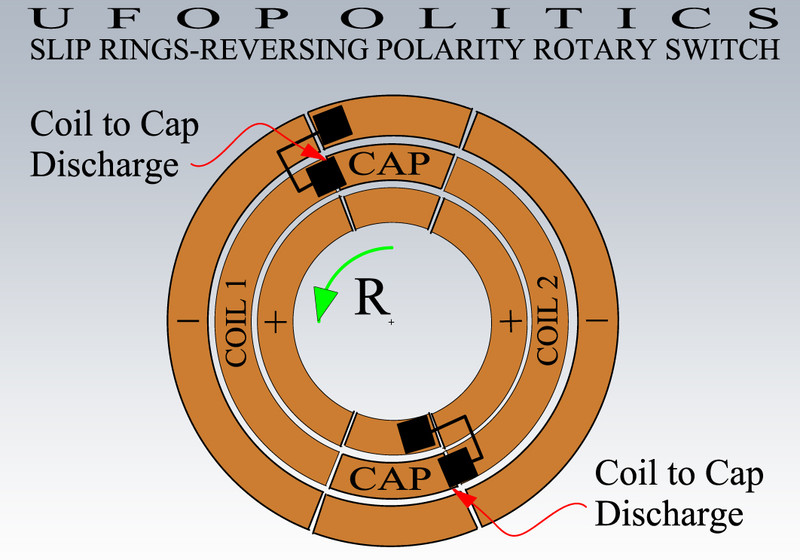
                        Below is a better view of the way brushes are positioned related to Slip Arc Segments, as I am showing BOTH Discharge Times in One Cycle from Coil to Cap


                        And...


                        Note that supply brushes are Off from supply arc, by the time Coil Brush is discharging to AC Cap on both positions...


                        Ufopolitics
                        Hello to All,

                        I quoted myself above on a previous post (WHICH IS VERY WRONG!!) when I was "theorizing" how COILS DISCHARGE COLLECTION SHOULD WORK...since the way I was figuring out to collect the COLLAPSING FIELDS discharge into an AC Cap was WRONG, it did not work as I expected to perform...

                        Above I was using the CENTER smaller arc segments to be connected to an AC cap (NOT the AC Cap connected to Exciter Coil!!...but another one) to collect a reversing spike twice per cycle.

                        SO...THE WAY IT REALLY WORKS WOULD BE SHOWN AND EXPLAINED BELOW:


                        Above Image shows Brush positioning for Cycle 1 where Coil has been disconnected from SOURCE LARGER arc segments, positive AND Negative, As now Coil is Discharging into the Positive and Negative Small 45º Segments Below AND Above, respectively:

                        Dual -Jumped- Brushes ON TOP (OUTER SET) are connecting Mid Arc Coil Terminal 2 (COIL2) to OUTER NEGATIVE Small Arc Segment.

                        ...while...

                        Dual -Jumped- Brushes BELOW (INNER SET) are connecting Mid Arc Coil Terminal 1 (COIL1) to INNER POSITIVE Small Arc Segment.

                        We can see the TWO small magenta circles area (Above and Below) where SPARKS 1 & 2 are generated, this occurs when Source+Coil Segments are jumped for a very short fraction of time.

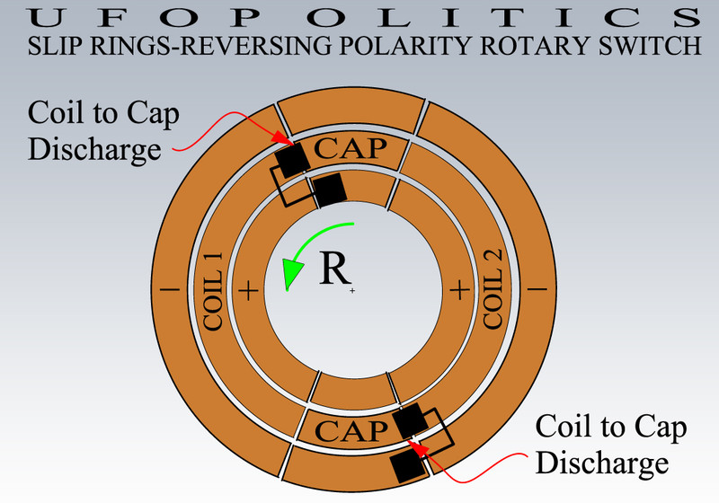
                        NOW, BELOW IMAGE ON CYCLE 2, Set of Brushes have traveled exactly 180º:


                        Here, each set of brushes have traveled 180º, therefore, the whole scenario switched as well...

                        Now the TOP SET is making COIL 2 TERMINAL discharge its REVERSED SPIKE into the TOP INNER smaller arc segment as a Positive charge...

                        While the BOTTOM OUTER SET is now Discharging COIL1 TERMINAL into the OUTER LOWER arc segment with a NEGATIVE Charge.

                        NOW THE WAY IT IS CONNECTED TO ELECTROLYTIC (OR ULTRA CAP) BANK


                        The collection of these REVERSED VOLTAGE spikes takes place on TWO CYCLES as you could see above, and they are pretty high in Voltage as of very low Amps, However, when connected to a Cap Bank, this Stored Energy could go as high as 100V Plus...IF NOT LOADED.

                        I have blown a few LED Lamps and a small Brushless Fan, due to just a MOMENTARY bad connection which broke off the bank and load...then reconnected it (while it kept charging from rotary switch)...and so...it blew them all...

                        So, the Diagram above shows how I jumped BOTH OUTER SMALL SEGMENTS, which are ALWAYS NEGATIVE.

                        As BOTH INNER SMALL ARCS which are ALWAYS POSITIVE.

                        This way I collect from BOTH "TEMPOS" (or CYCLES)...doubling the currents collection at Cap Bank.

                        I set TWO diodes (D1+D2) in order NOT to have those Small Arc Segments PLATES at switch... ALWAYS CHARGED by the Higher Energy from the Cap Bank...reducing the sparking considerably.

                        THIS TIME...All this Diagrams above are BACKED UP by EXTENSIVE REAL TESTING...AND NOT JUST THEORIZING!!!

                        With this Collected Energy I power up the Brushless cooling fans for switch and Cores.

                        Now, the higher the speed or frequency...the slower the Energy captured and stored...and viceversa, the lower the speed the higher the charge gets...HOWEVER, when Outer GENERATING Coil(s) are LOADED...There is an "Automatic" INCREASE of Energy flowing back to Caps Bank...just like an automatic cooling system works...


                        Regards


                        Ufopolitics
                        Last edited by Ufopolitics; 11-03-2017, 07:52 PM.
                        Principles for the Development of a Complete Mind: Study the science of art. Study the art of science. Develop your senses- especially learn how to see. Realize that everything connects to everything else.― Leonardo da Vinci

                        Comment


                        • The middle pieces of the small section are not attached to anything?

                          Also, this is exactly what Figuera was describing in the patent, constantly reversing magnetic moments while also harvesting as much as possible back from the electromagnets.

                          It strikes me that because a coil can be a capacitor, would it be feasible to replace the capacitor bank with another set of coils undergoing the same changes? Twice as many opportunities to harvest for a given disturbance.

                          Maybe this is what he meant when he drew the rows of electromagnets?
                          Last edited by Diplomacy; 11-03-2017, 06:05 PM. Reason: Wrong word

                          Comment


                          • Originally posted by Diplomacy View Post
                            The middle pieces of the small section are not attached to anything?
                            Hello Diplomacy,

                            That is correct, mid small pieces are not utilized on this way brushes are set. They are just a "brake pad" (idle) between coil reversals.

                            Originally posted by Diplomacy View Post
                            Also, this is exactly what Figuera was describing in the patent, constantly reversing magnetic moments while also harvesting as much as possible back from the electromagnets.


                            Originally posted by Diplomacy View Post
                            It strikes me that because a coil can be a capacitor, would it be feasible to replace the capacitor bank with another set of coils undergoing the same changes? Twice as many opportunities to harvest for a given disturbance.
                            Only thing here Diplomacy...is that those Collected Spikes are pretty low in amperage, like I wrote on the previous post.
                            They only gain strength when stored in a Bank...and the good thing is they WILL fill up Ultra Cap Banks as well...however, takes longer than typical caps do.

                            But yes, in general remember just one rotary switch would be running several other Exciter Coils, then we set them in a Magnetic Chain and "Insert" other Generating coils in between (Buforn Patent)...and so on and on...

                            Originally posted by Diplomacy View Post
                            Maybe this is what he meant when he drew the rows of electromagnets?
                            Could be...


                            Regards


                            Ufopolitics
                            Last edited by Ufopolitics; 11-03-2017, 07:40 PM.
                            Principles for the Development of a Complete Mind: Study the science of art. Study the art of science. Develop your senses- especially learn how to see. Realize that everything connects to everything else.― Leonardo da Vinci

                            Comment


                            • DC power in DC power out

                              Hi UFO,

                              Do you have any DC power In/Out measurements you can share yet?

                              Regards

                              L192

                              Comment


                              • Originally posted by bistander View Post
                                Hi Ufo,

                                Here's a diagram:


                                So channel A is current (measuring millivolts across the shunt) and channel B is voltage. The source, represented by the circle with sinewave in that diagram, is your power supply (PSU). The ground is the PSU negative terminal. Ground is common between channels A & B.

                                If for your test condition the scope shows straight lines (DC) then note the magnitude and check against digital meters on the PSU. If those match then you can move the scope to the output and do a similar measurement.

                                Hope that clears it up.

                                bi
                                Hello L192,

                                Above is a previous post from Bistander at page 82, proposing a simple test with shunt at Input then at Output...(you could go back then watch all my questions-answers by Bistander, related to method) at that time I was still working on this new rotary system, where I reverse Fields...and since it tested out very successfully, I would be doing this tests with it, instead of the single positive only, brush driver.

                                Those tests above are in a "primarily order" still pending to be demonstrated by a video.

                                Now, I work based on "Trial-Error" basis...and so, successful tests keep refining until achieving Top results, unfortunately I do not have such high budget, where I could afford to keep all my previous Coils intact, then keep buying new ten pounders wire spools back and forth...I only wish I could do it that way...but can't.

                                Therefore, my way to go on this development, is by winding-unwinding previous coils geometries which did not work as expected, also recycling the tape I use on each, and so on and on...this is ok...only thing here that is consumed in huge amounts... is time...more time.

                                I decided to SPLIT Exciter Coil in TWO Parts...hoping it would perform better, since a split iron core worked better than a full one (and here, "theoretically speaking" I thought by generating Three Dielectric Fields involved in TWO Coils, instead of just ONE in a single full coil)...And so, unfortunately... NOPE, it did not worked as I expected, it did Induced EMF as well, but never like a full coil...then time to unwind...put them on empty spools...and prep a new mold to host the old full exciter coil type(so this time I could slide it in-out, where previously I couldn't)...then I decided to add more wire layers which allows me to dial higher voltages while limiting current to only 2 Amps...and so, right now, that's what am working on...testing different layers on top of the original set up which worked out fine...

                                I got the new meters last week, and have not had the time to even unpack them...as well as a new 14 awg ten pounder roll...also unpacked.

                                I want to reach first a pretty solid way to EXCITE STRONG Fields with adequate Higher Voltages which fully drive the 2Amps currents in REVERSE MODE properly at the operating speed/frequencies...and that takes time.

                                For that reason, after the diodes bridge DC rectification, basically voltage is dropping off too much with typical resistive loads like the 50 Watts Halogen Bulb, while amperage is still very high. This does not takes place with AC Output (Before diodes) with same bulb. And yes, I DO have the filtering cap of 100uF/200V.

                                For the test that you are proposing (DC IN-OUT) which sounds very simple right?...well, I need to find the appropriated DC LOAD...one that fully runs, while being able to show meter read outs clearly.

                                At the same token...I have found that an AIR CORE (No Iron Rod) works as well or EVEN BETTER, than iron cylinder Core...just copper coils...Iron works better whenever is NOT PLACED AT CENTER of Coils...and basically steel tubing will do better than solid rods.

                                It seems the FAST REVERSING FIELDS, can react/response MUCH FASTER in OPEN AIR, than having the restriction of iron molecules changing their polarization faster than they can handle to keep up with a completely VIRTUAL FIELD, which goes through iron like a sharp knife through a Butter Block...reason why core gets so extremely hot!!

                                One rule of thumb I have found out...is that IF the Iron core is not getting hot...then your Exciter Coil SPEC'S are NOT CORRECT, not reversing iron particles as fast, which normally causes internal friction/heat...Iron Core should get hot, while coil wire is just warm under some extended operating time.

                                As soon as I can show something...I will do so.


                                Regards


                                Ufopolitics
                                Last edited by Ufopolitics; 11-16-2017, 03:13 PM.
                                Principles for the Development of a Complete Mind: Study the science of art. Study the art of science. Develop your senses- especially learn how to see. Realize that everything connects to everything else.― Leonardo da Vinci

                                Comment

                                Working...
                                X