 Tweet
Tweet
To ElCheapo
@ElCheapo,
Forgot to suggest one small change in your coils setup...if you could do it with minor changes.
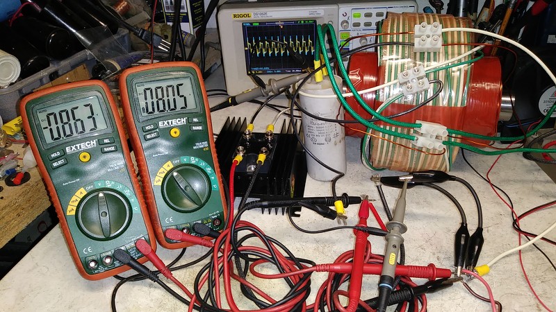
Take your your y coil off then get the two exciters coils and cores and approach them without touching iron to iron, could use a small rubber damper as gap and Idk if you have bolts on them, which would be ideal to prevent high vibrations, this gap is approx around 5 mm.
Then wrap your y coil ABOVE and around BOTH Exciters LENGTH, trying to reach both ends...normal winding, back and forth layers.
Then test it...
Regards
Ufopolitics
@ElCheapo,
Forgot to suggest one small change in your coils setup...if you could do it with minor changes.
Take your your y coil off then get the two exciters coils and cores and approach them without touching iron to iron, could use a small rubber damper as gap and Idk if you have bolts on them, which would be ideal to prevent high vibrations, this gap is approx around 5 mm.
Then wrap your y coil ABOVE and around BOTH Exciters LENGTH, trying to reach both ends...normal winding, back and forth layers.
Then test it...
Regards
Ufopolitics


Comment