 Tweet
Tweet
Visualizing the Magnetic Fields...
Hello to All,
I find this Project really fascinating!
Ok, while some of you have been concentrating on your builds as other worries...I have been trying to "visualize" what is going on with the Magnetic Fields within the cores of the Inducers including the Core from part G...:
[IMG]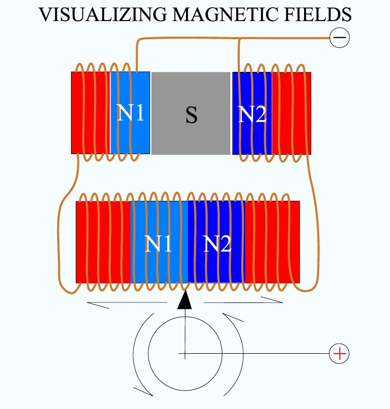 [/IMG]
So, this is my take on what is happening, trying to understand what Marathonman have carefully being explaining so far.
In above simple diagram, I have set N1 for the Primary 1 on left upper, as N2 for second Primary 2 at right. Please note that I did both windings Opposite, relative to where they are feeding negative as reference.
I also did part G Core in a straight fashion to help visualize what is going on here. Please note that -as MM said- the winding at partG Core is a CONTINUOUS One.
I have shown arrows for linear movements of the Positive Input Signal, then reflected at lower section, when taking it to a Rotary displacement.
All that is fine...However, the important part I consider here is what is going on with Magnetic Fields?
First let's picture the Part G CONTINUOUS COIL AND CORE...and currents traveling, causing it to Energize.
It receives a Negative Voltage Polarity transferred through both terminals coming from both Primaries...Plus it has a "moving" or could say "floating" Positive Input from Brush, therefore, based on that feed it magnetizes according to the Dual Magnetic Fields I have reflected, which in turns generates Two Polarizations for each Field. I have also named them as N1-N2 considering they are just same fields being "reflected" from Both Primaries.
Now please try to visualize what Magnetic Field displacement takes place whenever we start moving that "Floating" Positive Signal.
Yes, exactly that!...We are just "redoing" or could say "Echoing" or "Mirroring" the same Magnetic Field Process that is taking place between Primaries-Secondary, which consists on displacing Both N1-N2 along its ferromagnetic core and coils...Therefore, we are "Self Inducing" our Part G Continuous Coil by the displacement from their own currents coming back and forth from Primaries by constantly moving that floating positive signal.
This -I believe- is the main reason why Marathonman keeps repeating that the System is "Self Sustained", since we have this process perpetually bouncing back and forth, as long as we keep the North Polarizations N1-N2 displacing along the Part G Core.
It is nothing more than a very beautiful...and very Elegant way to keep a Constantly Renewable Magnetic Field Process between Part G and the Primaries.
This is the reason why we must make sure all our Iron Mass plus number of windings should be carefully balanced, in order that there will be the least of losses in this beautiful magnetic exchange network.
Next I am working on the correct relation (wirings) between Linear displacement transferred to rotary movement of the positive signal.
Regards to All
Ufopolitics
Hello to All,
I find this Project really fascinating!
Ok, while some of you have been concentrating on your builds as other worries...I have been trying to "visualize" what is going on with the Magnetic Fields within the cores of the Inducers including the Core from part G...:
[IMG]
 [/IMG]
So, this is my take on what is happening, trying to understand what Marathonman have carefully being explaining so far.
In above simple diagram, I have set N1 for the Primary 1 on left upper, as N2 for second Primary 2 at right. Please note that I did both windings Opposite, relative to where they are feeding negative as reference.
I also did part G Core in a straight fashion to help visualize what is going on here. Please note that -as MM said- the winding at partG Core is a CONTINUOUS One.
I have shown arrows for linear movements of the Positive Input Signal, then reflected at lower section, when taking it to a Rotary displacement.
All that is fine...However, the important part I consider here is what is going on with Magnetic Fields?
First let's picture the Part G CONTINUOUS COIL AND CORE...and currents traveling, causing it to Energize.
It receives a Negative Voltage Polarity transferred through both terminals coming from both Primaries...Plus it has a "moving" or could say "floating" Positive Input from Brush, therefore, based on that feed it magnetizes according to the Dual Magnetic Fields I have reflected, which in turns generates Two Polarizations for each Field. I have also named them as N1-N2 considering they are just same fields being "reflected" from Both Primaries.
Now please try to visualize what Magnetic Field displacement takes place whenever we start moving that "Floating" Positive Signal.
Yes, exactly that!...We are just "redoing" or could say "Echoing" or "Mirroring" the same Magnetic Field Process that is taking place between Primaries-Secondary, which consists on displacing Both N1-N2 along its ferromagnetic core and coils...Therefore, we are "Self Inducing" our Part G Continuous Coil by the displacement from their own currents coming back and forth from Primaries by constantly moving that floating positive signal.
This -I believe- is the main reason why Marathonman keeps repeating that the System is "Self Sustained", since we have this process perpetually bouncing back and forth, as long as we keep the North Polarizations N1-N2 displacing along the Part G Core.
It is nothing more than a very beautiful...and very Elegant way to keep a Constantly Renewable Magnetic Field Process between Part G and the Primaries.
This is the reason why we must make sure all our Iron Mass plus number of windings should be carefully balanced, in order that there will be the least of losses in this beautiful magnetic exchange network.
Next I am working on the correct relation (wirings) between Linear displacement transferred to rotary movement of the positive signal.
Regards to All
Ufopolitics


Comment