If this is your first visit, be sure to
check out the FAQ by clicking the
link above. You may have to register
before you can post: click the register link above to proceed. To start viewing messages,
select the forum that you want to visit from the selection below.
"Today's scientist have substituted mathematics for experiments and they wander off through equation after equation and eventually build a structure which has no relation to reality."
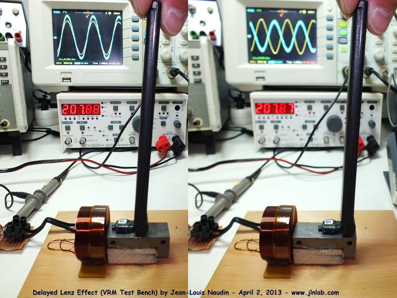
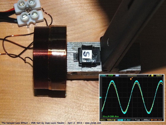
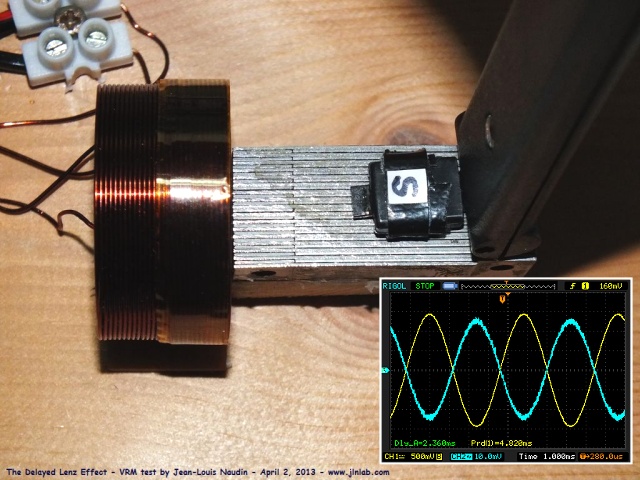
I have found this in a video on the delay that occurs in the magnetization of a metal core. As you see in the video, the magnetic field is delayed as a probe is moved away from the inductor's until reaching 180 degrees compared to being in phase (0 �) for short distances. This is called Delayed Lenz Effect . If the delay in the magnetization of the core makes this field to be delayed half wave, imagine: the magnetic field is delayed half cycle. If in that postition you place one collector coil and induced current is generated. The induced field would take another half cycle to return to the electromagnet and affect it: 1/2 cycle + 1/2 cycle = 360�. Thus, instead of opposing to the electromagnet it could be coupled to it and amplify the effect. It is the case of a swing: If the swing, in the return way, just change direction at the time that a force is applied the effect is amplified effortless ... you should calibrate the timing to push the swing to give the boost at the right time, otherwise you could brake it. I could be wrong but apparently it seems that between being the inducers and the induced close (with offset 0 �) and suffer the effect of the law lenz opposing, and being away (offset 180�) maybe that effect serve to "help" rather than to brake.
I mention this in order to document the forum. For now I will not try all these things. But it seems to me curious as one user who said to get it running said he had to move the induced coil , also in the forum about bucking coils people are using insulation between coils (plastic spacers) (loose coupling) , Buforn and Figuera were cryptic about the placement of the coil: the coil has to be "properly placed" as literally they wrote on all patents since 1908, also I have seen a video where in Hendershot generator the distance between coils had to be adjusted. It seems like there's a spatial issue (placement) which is beyond our understanding ... Anyway, here I put it to have it documented, who knows if someday someone will come and find all these useful. Please see the video, it is very interesting:
Hi Hanon.
I think it is all about a delay in the magnetic wave propagation
AND reflecting that wave with a certain type of a load.
I am in the process of replicating this type of transformer.
[VIDEO]http://www.youtube.com/watch?v=AWcd9SKR7-Q[/VIDEO]
Here, the core has properly spaced coils with long sections of the core
to use as a delay line for the magnetic flux wave.
Why did Buforn change so radically the writting about the placement of the induced coil comparing his patents from 1910 and 1911?
Could he try to hide the key feature for running the generator? It got me thinking... ???
1910 patent: Induced coil core without touching the electromagnets cores
1911 patent: Induced coil core always must touch the electromagnets core
Both patents are exact copies of the 1908 Figuera patent. The only difference between 1910 and 1911 patent is this feature. I tend to think that Buforn filed a new patent in 1911 in order to hide the key features of this device...
I collect here an idea that already appeared in the forum about generating the two signals for the Figuera 1908 patent with a very simple method.
Suppose that each inducer is composed by two coils: One coil feed with DC current and the other coil feed with AC current. In inductor 1 you could place both coils so that both magnetic fields (from the DC and AC) add up in the first half cycle of the AC signal. In the inducer 2 you could place both coils to subtract their magnetic fields in that half cycle. Later, during the second half cycle, the polarity of the AC signal will reverse and in the inducer 2 both fields will add up while those fields will cancel in inductor 1.
With this layout I think you could get both opposite signals with a very easy setup. I post here an sketch in order to make it clearer for other users.
Although currently I am not doing experiments there is no day when I do not think about the Figuera generator. But I am reading many things trying to find similarities that give clues and help solve the puzzle.
For a month now I've been reading things about Gennady Nikolaev, Russian scientist who proposed an amendment to the electromagnetic equations of Maxwell to include the existence of longitudinal waves. He demonstrated experimentally the existence of these waves (there are several videos on Youtube but they are in Russian ... and I do not understand). They are longitudinal waves are those waves used in Tesla�s power wireless transmission. This scientific postulates that a second magnetic field, a magnetic field scalar not predicted by the current equations which predict only a transverse magnetic field. This field is the one that says that accommodates all overunity systems. It seems that his designs to get this field require two magnets with opposite poles very close.
For me what Figuera�s patent have in common (both 1902 as 1908) is that in all of them Figuera always used TWO electromagnets. Among them, in the center, it is placed the induced circuit. Using two magnets located very close is related to the proposed Nikolaev ideas.
Look what Nikolaev tells us:
Top photo: "In the middle of two magnets with the opposite poles (situated in one plane) the total vectorial magnetic field vector is zero, which is proven by the absence of magnetic interaction between magnets and a ferromagnetic material. This ferromagnetic material is placed in the space where usual magnetic field is zero. However, in the space where the total vector magnetic field vector of the two magnets is zero, the total value of the scalar magnetic field of the two magnets is maximum. In spite of this fact, the magnetic scalar field between magnets is maximum, this field does not interact with ferromagnetic materials. That is why the ferromagnetic material on the tray is not attracted to magnets. However if we create electric currents (or equivalent Amper�s currents of this double magnet) in this space, where usual magnetic field is zero, than under the action of longitudinal interactions of these currents with the total magnetic field of the magnets scale the forces of attraction or repulsion appear"
Bottom photo: "It is a device to demostrate the existence of longitudinal electromagnetic waves. Two loop antennas are emitting the antipodal waves. That is why the total signal of transverse electromagnetic waves in the plane between the loops is equal to zero. However, the longitudinal electromagnetic waves have the maximal value in the plane between the loops. These waves are easily recorded by the loop antennas, even in spite of fact that the plane of the loop antennas appears to be perpendicular to the plane of polarization vector of transverse electromagnetic waves. Any registration of transverse electromagnetic waves is impossible in this case. "
----
This scalar field is allowing this rare effect between three magnets: the creation of a magnetic coupling or well where the attraction and repulsion are canceled: https://www.youtube.com/watch?v=dtiMQPeYJrQ
I always recall to read the original patent text in detail to look for the right coil placement.
In the 1914 patent (Patent No. 57955 and filed by Buforn, a partner of Figuera) you can read:
"If you want even greater production you can place the inducers and the induced one after the other forming a single series in the next way: you place first an electromagnet N, for example, next another electromagnet S, and between their poles and properly placed you put the corresponding induced, with this we will have formed a group of battery as explained before, but now (instead of forming as many identical groups to the first one as number of induced coils needed) you can place, following the last electromagnet S, another induced and, after this last induced you can place an inducer N, following this inducer by another induced, and then by another S, and so on until having placed all the inducers which form the series of electromagnet N and S.
With this we will have succeeded in using the two poles of all inducers except the first and the last one of which we will have only used one pole and, therefore we will have as many inducers as induced minus one, this is, if “m” is for example the number of inducers, then the number of induced will be “m – 1”, which determine a considerable increase in the production of the induced current with the same expenditure of force."
--------------------------
For me it is clear that all electromagnets are arranged in a linear way (straight bar core type). Therefore you can use with this design both poles of each electromagnets in contrary to the use of just one pole of each electromagnet as in the original 1908 design.
For me it is clear that electromagnets are just solenoids , not any kind of transformer core type. Please open your minds and recall the generators from Hubbard, Hendershot and others where the cores are not forming any king of close transformer.
Here is the link the partial translation of the 1914 patent (sorry but it is 30 page long and it is too much time for me to translate it completely, more when it is practically a copy of the 1908 design plus some improvements as the ones explained in the translation that I attach)
" Another advantage is that around the core of the induced electromagnets we can put another small size induced electromagnet with equal or greater core length than the large induced one. In these second group of induced an electric current will be produced, as in the first group of induced, and this produced current will be sufficient for the consumption in the continuous excitation of the machine, being completely free all the other current produced by the first induced electromagnets in order to use it in all purposes you want. "
Why is required that the induced coil for the self-sustaining to be of equal or greater length than the coil for electrical output ?
I have a theory for this: Maybe the patent require this configuration because both induced coils are having induction done by the flux cutting the wires (as in generators), not by flux linking (as in transformers). If induction is done by flux cutting (as consequence of the moving magnetic fields from one side to the other) then, the coil for the internal consumption of the machine is better to have a longer length to assure a continuous production of electricity, avoiding any instant without wires being cut by the lines of force, as may happen with a shorter coil while the magnetic fields are moving. All this is just my guess. In other case I can not explain why this configuration is required.
Any other ideas for explaining this configuration?
Quoting another pragraph from the patent from 1914 (Buforn) with some cryptic sentences:
"The way to collect this current is so easy that it almost seems excused to explain it, because we will just have to interpose between each pair of electromagnets N and S, which we call inducers, another electromagnet, which we call induced, properly placed so that either both opposite sides of its core will be into hollows in the corresponding inducers and in contact with their respective cores, or either, being close the induced and inducer and in contact by their poles, but in no case it has to be any communication between the induced wire and the inducer wire."
Why did he make reference to two cases: 1- when there is contact between the induced and inducers cores and, 2- when they are close together and in contact by their poles ? Which is the difference between contacting through the cores and contacting through the poles?
Why did he mention that "in no case it has to be any communication between the induced wire and the inducer wire" ? At first sight it seems to be a redundant feature, does it?
Please comment your thoughts about these sentences. I am not able to understand their real meaning. I do not understand why Buforn emphatize those details.
Note how I see this configuration. Also this configuration is the one used in the 1902 patent. I also attach an image from 1902 patent (Patent no. 30378): two straight solenoids (named "a" and "b") and the induced in the middle (named "c", not drawn in the patent, so not clear how to place it)
That why I always say to dig into the original sources.
In case of using a bucking coil design and just pulsed current in the two inducers, as described in the 1902 patent:
This is a configuration that -I think- should cancel completely the Lenz effect resulting from the group of two bucking induced coils:
Two inducers and two output bucking coils. Inducers have like poles facing each other (North - North , or South - South ) , therefore the system is simetric and each induced coil is trasversed by each inducer field. The induced current add up to contribute to the final voltage output, while at the same time both induced field cancell each other.
INDUCER (North) -----> TWO BUCKING COILS <----- (North) INDUCER
Where both inducers are creating a North pole toward each bucking coil (same inducer poles facing each other North-North). Their fields crash in the ce3nter point and are expelled from the iron core. This way each bucking coil is transversed by a different inducer field.
Connecting properly the induced coils, both induced voltages add up, while both induced magnetic fields cancel out.
I have being modelling in Excel the commutator described in the 1908 patent. Quoting the patent: � Let be �R� a resistor that is drawn in an elementary manner to facilitate the comprehension of the entire system. �
I have done the simulation of the original commutator, as described in the patent, and also the simulation of an modified commutator consisting of two independent resistors. Using two independent resistor one for N-Coils and other for the S-coils (but both connected to the rotary brush device) it is easier to get two symmetrical signals for each array of inducers. With just one resistor the available values of resistances and impedance of the coils are more restricted to get a good output signal because the resistance of one array and the other array are mutually dependent. Using two resistors we get an extra degree of freedom and we may use more resistance values to get a better shape in the output signals. For those who use the Excel spreadsheet the input values to the simulation are the cells in green.
I include here the simulation of both systems but, according to the patent quote, it won�t be difficult that Figuera just drawn it in such a way to make easier its understanding; but maybe he envisioned an optimized commutator to get a better signals to each inducer coil array (N and S).
Patrick Kelly has updated in his ebook the info referred to the Figuera Generator. Now the info presents with a higher degree of fidelity the original concepts included in Figuera�s patents
Apart from the 1908 patent, in the book now it is also included new info from the two patents filed in 1902: the motionless generator (patent no. 30378) and the generator with the rotary coil (patent no. 30376)
Although this thread is not much alive I try to use it as a kind of blog where I post new findings that are posted in OU forum where this subject keeps alive.
Some time ago a user in OU forum posted the sketch that I attach below.
Note how he alternated the polarity along each electromagnet serie in order to get close magnetic circuits with all the electromagnets. He added two external iron bars (in black) to get those close magnetic circuits. Closing the magnetic circuit will get more powerful electromagnets and enhance all magnetic effects
I for one appreciate your updates here. I wasn't aware of the PJK update, so that was particularly welcome as there's quite a few things added. I didn't know that there were any other patents besides what PJK had already shown either. That new one where the coils would be powered directly by AC is intriguing - straight-AC for one side and cap-phase-shifted-AC for the other, much simpler to implement nowadays, so why aren't there any builds doing this?
That diagram you've attached kinda makes sense, but it got me wondering as to why the original setup isn't in a ring formation - as it is, 2 poles of each driver-pair are unused, put them in a ring, double your number of output coils and you automatically double your output-power, and all for zero extra input! Or am I missing something obvious?!?!?
 Tweet
Tweet


Comment