Announcement

Collapse
No announcement yet.

Re-Inventing The Wheel-Part1-Clemente_Figuera

Collapse
X
 
  • Filter
  • Time
  • Show
Clear All
new posts

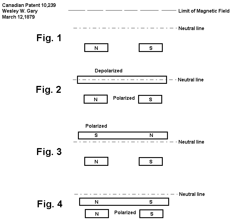
  • One doubt: suppose that we really have opposite poles facing each other (N <--> S) in the inducers. If the inducer north pole is increasing in intensity it will produce (lenz law) a north pole in the induced coil side close to it. An if the inducer south pole is decreasing in intensity it will ALSO produce a north pole in the induced coil side close to it. Two north poles induced at the same time: no good for induction ( explaining in other way: one inducer is incresing the field along the induced coil while the other inducer is decresing the field along the coil. Result: the net field change is almost zero) or, maybe will two south poles appear inside the induced coil ? Could this imbance in the field 1("opening flux valve") and 2 ("closing flux valve") escape from that induced coil in some way? Maybe this last question is the answer: I posted an schematics drawing the "escape" of the flux lines from the induced core in each "swing" of the electromagnets

    A completely different situation will appear with like poles facing each other (N <--> N or S <--> S): a incresing north in one side will create a induced north , and a decresing north in the other side will create a induced south. Good.

    Also the good thing about like poles facing each other is that there will be induction by flux linking PLUS induction by flux cutting -->

    E = S · dB / dt + B · v · Length

    beeing "v" the relative speed that flux lines cut each wire laterally

    The flux linking induction will be limited by the lenz law effect, but maybe the flux cutting induction will not suffer any dragging force because there is no movement. What do you think?
    https://figueragenerator.wordpress.com/

    Comment


    • Originally posted by hanon1492 View Post
      Hi all,

      In overunity.com forum a user believes that the real configuration of the Figuera´s patent is with like poles facing each other.


      My impression is not clearly in favor or against this view because the only sentence in the 1908 patent where it is defined the poles orientation is written as follows: "Let`s suppose two electromagnets represented by the rectangles N and S". Nothing more and nothing less. Maybe it was just a "patent notation" trick to hide the real pole orientation.

      Suppose two like poles facing each other and with their flux lines repepling and swinging back and forth along the changes in intensity in the electromagnets. Those flux lines cross partially the central induced coil and also cut the induced wire during his swinging motion up and down.

      As you can see in this scheme there is induction by 2 mechanisms:
      1. Induction by Flux linking along the part of each coil transversed by the flux lines
      2. Induction by Flux cutting the induced wire


      We could have both types of induction into the same device.The key in this scheme is that the induction by flux cutting to be greater than the induction by flux linking. (the flux linking induction is under the Lenz Law effect and will produce an opposing induced magnetic field which will reduce the inducers strength)

      The good part of this idea is that if the flux cutting induction by an N-N configuration will induce in the sense to reduce the inducers field (due to the Lenz effect), then the S-S configuration will do it in the sense to increase it because the flux lines in each case have opposite direction (from inside-out or from outside-in).


      Any comments?
      Your theory, is in my opinion, very stable. Its interesting how the majority of posters on this topic have not made this spring to opposition versus cooperation. You are most certainly in my opinion, one of the few whom I believe can see whats really going on!

      Experience has taught me much of what is seen in this patent like many others like it are red herring time wasters. Once you find them and remove them from the picture, a new image emerges. Why are there so many "cells" required? This question can only truly be answered when you have built and tested something.

      I am of the opinion that owing to the difference in coupling, the output of the design under discussion is lower than that of a machine of conventional design. For this reason, the multiple "cell" topology "may" have been adopted. It has been my experience while working with systems where fields oppose, that the mechanical reaction assists in the direction of rotation, "IF" the generator phase is in proper relation to the motor phase (timing of impulses applied to the motor, pulse duration isn't as important as "when" the pulse is applied with relation to the induced EMF in the generator...). Acceleration is the rule in this case and not an acceptation to the rule. And before anyone suggests delayed Lenz, no....I am claiming that when we adopt the proper geometry, and establish the proper phase relation between motor and generator circuits, the Lenz observation functions to assist versus to oppose.

      Also noteworthy, my system does not incorporate ferrous material, it is composed of air core coils only! Inductance of my coils is under 50mH, and rotor speed is kept under 2500rpm, this rules out any chance of my device operating in "resonance".

      Hannon1492, again, of all the posters on this and related threads, you are one of the few whom in my opinion is even close to having a working idea of whats going on in this, and related (Tesla - 381,968) devices.

      Regards

      Comment


      • UFO thought the following design might be of interest

        same period : Antonio d'Angelo -- Inter-Atomic Ion Motor -- NY Times article & US Patent # 2021177

        New York Times (Wednesday, March 7, 1928)


        Priest Has Motor Run By 'Ion Energy'
        the schematics are quite interesting
        Signs and symbols rule the world, not words nor laws.” -Confucius.

        Comment


        • Hey guys

          I thought I would post my small 2 phase I'm working on. I think if I can get the two phase working, I'm almost done, and the rotating field works, maybe we'll have a better idea. I still have to, wind 2 phase, install slip rings, then I can energize toroid, before it gets mounted. I'll post the parts being put together, once its fininshed,...if it works..

          2 phase build in progress - YouTube

          Comment


          • Different Systems

            Hi All,
            I guess I have made another version for contemplation, Regards Arto

            Comment


            • Why not this way : N and S are in series and wound with fine wire, big self-inductance, output coils in parallel.commmutator is for switching each pair (N and S) OFF sequentially from left to right and back. coils are powered all the time..this looks much more similar to Chernetsky

              Comment


              • Small Adjustment

                Same pics just now Parallel/serial output...Arto
                Last edited by artoj; 11-25-2013, 04:07 AM.

                Comment


                • I had disruption

                  Did everybody see the last post, the system jumped me to another thread, when I posted?

                  Comment


                  • Originally posted by machinealive View Post
                    Hey guys

                    I thought I would post my small 2 phase I'm working on. I think if I can get the two phase working, I'm almost done, and the rotating field works, maybe we'll have a better idea. I still have to, wind 2 phase, install slip rings, then I can energize toroid, before it gets mounted. I'll post the parts being put together, once its fininshed,...if it works..

                    2 phase build in progress - YouTube
                    Hi machinealive,

                    Good luck in your endeavour!! I am not an expert in motors so I guess that what you are trying to do is to rewind a normal one phase motor into a two phase motor and make it rotate to use it as a 2 phase generator.

                    Keep us up to date of your progress!! You are getting closer!!

                    Regards
                    https://figueragenerator.wordpress.com/

                    Comment


                    • thought it fit nicely here as it matches Figuera's aim:

                      Gustave LeBon: The Evolution of Forces ~ Part II

                      2. The Problem of Induction

                      The same problem is equally present in the case of magnetic induction. How, with a definite quantity of magnetism, can we produce an apparently unlimited quantity of induced electricity?

                      By cutting the lines of force of a magnet by a metallic wire
                      forming a loop, of which the extremities are connected with the terminals of a galvanometer, we verify during the passage of the wire through the lines of force the appearance of a so-called induction current. It suffices to continuously displace the metallic wire in the magnetic field, so long as the displacements are repeated.

                      On this fundamental fact of the production of a current by a conductor cutting the lines of force are based our magneto-electric machines, from which dynamos only differ because here an electromagnet takes the place of the fixed magnet. We will only consider here the first-named, which will enable me to make our demonstrations clearer.

                      In these magneto-electric machines, the single wire referred to above is wound on a drum revolving between the poles of a fixed magnet, so as to cut again and again its lines of force. So long as the coil continues its movement, the magnetism of the magnet will be transformed into electricity. With a finite quantity of magnetism, we therefore produce an unlimited quantity of electricity.
                      THE INTERFERENCE DISK ELECTRIC GENERATOR BY ALAN L FRANCOEUR from The Encyclopedia of free energy,energy21.org,energy 21 org Geoff Egel

                      Last edited by MonsieurM; 11-27-2013, 06:33 PM.
                      Signs and symbols rule the world, not words nor laws.” -Confucius.

                      Comment


                      • you see there is a weak point : MOVEMENT require work done

                        Comment


                        • Figuera (patent No. 30378, year 1902):

                          "[The authors] believe that it is exactly the same that the induced coil cut the lines of force, than that these lines of force cut the induced wire"


                          The idea is quite clear. Now the objetive is to know how to get it done.

                          How should we configure the electromagnets and the induced coil in order to get this induced coil cut by the lines of force?
                          Last edited by hanon1492; 11-28-2013, 11:44 PM.
                          https://figueragenerator.wordpress.com/

                          Comment


                          • Originally posted by hanon1492 View Post
                            Figuera (patent No. 30378, year 1902):

                            "[The authors] believe that it is exactly the same that the induced coil cut the lines of force, than that these lines of force cross the induced wire"

                            The idea is quite clear. Now the objetive is to know how to get it done.

                            How should we configure the electromagnets and the induced coil in order to get this induced coil cut by the lines of force?

                            can't really answer that question , but the following seem to fit what you are looking for :

                            [(1) That lines of force also appear between conductors carrying an electrostatic charge can be shown by interposing between them a glass vessel filled with oil of turpentine and crystals of quinine sulfate. See Kolbe’s Introduction to the Science of Electricity, 1903, p. 125, et seq.]
                            Gustave LeBon: The Evolution of Forces ~ Part II


                            Let me recall, to put this essential point clearly in evidence, the classic experiment demonstrating electrification by influence.

                            A metallic sphere (Figure 1) placed on an insulated support is electrified in one way or another, and thus receives a definite quantity of electricity, the magnitude of which is easily measurable. Let us being near to this sphere at a little distance a conductor -- for example, a long cylinder of metal B, C, placed on an insulator D. We immediately recognize by the ordinary means that the cylinder is charged with electricity. If the ball has in the first instance received positive electricity, it will be observed that the part of the cylinder next to it is charged with negative and its other extremity with positive electricity. If, then, this latter is touched so as to connect it with the earth, the whole cylinder remains charged with negative electricity. This may now be transferred to some other body by moving the cylinder by its insulated support.

                            Figure 1


                            After having discharged the cylinder we have only, in order to recharge it, to bring it again near the ball and act as before. As these successive operations -- charge and discharge of the cylinder -- can be repeated an unlimited number of times, it necessarily follows that, with the limited charge of electricity on an electrified ball, there can be generated on another body an unlimited quantity of electricity.
                            1. The Problem of Magnetism

                            The problem which offers itself to us in the case of electrification by influence likewise presents itself as regards the phenomena of magnetism and of magnetic induction.

                            We know that a permanent magnet can magnetize an indefinite number of iron bars. A limited quantity of magnetism would therefore seem to produce an unlimited quantity.
                            Last edited by MonsieurM; 11-27-2013, 11:25 PM.
                            Signs and symbols rule the world, not words nor laws.” -Confucius.

                            Comment


                            • sometimes you need to search for common clues :

                              https://www.google.com/search?client...2++rexresearch :"line of force" + rexresearch

                              John Christie & Ludwig Brits: System for Controlling a Rotary Device

                              Summary of the Invention

                              The present invention is aimed at providing an improved rotary device which operates with improved efficiency compared to conventional rotary devices.

                              The present invention is also concerned with providing a system for controlling a rotary device which is able to generate electrical and/or mechanical energy.

                              According to the present invention there is provided a system for controlling a rotary device, the system comprising a controller and a rotary device, which has a stator and rotor, wherein the controller is connected to the rotary device to control rotation of the rotary device, and wherein the controller is adapted to periodically energize at least one energizing coil of the device to create a magnetic field of a polarity which induces the rotor to rotate in s single direction and wherein the controller is switched off so as to e-energize the energizing coil when other forces, being forces other than those resulting from the energized energizing coil produce a resultant force which induces rotation of the rotor in a single direction.
                              +

                              H. Perrigo: Aether Energy Electrical Generator


                              The aerials collect and transmit a flow of the ether or wave energy through the conductors from what ever direction the potentials of the ether are collected, and obtain a pressure of sufficient force to effect a movement in the direction of the least resistance from north to south, through the resistance coils 1 to 100, transmitting a flow of the ether medium or wave energy between all of the contacts on the plates 20+, 21-, the flow being governed by the lines of the least resistance, there following two pressures between the north and south poles of the first coil, the pressures being of opposite potentials, and caused by the
                              opposite polarity of the coils, and the electromotive force thus produced between the plates 20+, 21-, is constant, one line of force being broken by a line of force of a different potential, and these forces all tending toward a common polarity, while producing an electromotive force, in the opposing resistances of these opposite wave potentials. The method of obtaining electric energy as above described, resides in reciprocal lines of force being established by means of such broken circuits and resistances, as are found by practical results to produce an amperage of current or wave energy, and as the action of
                              the collective broken circuits with reversed polarities produce positive electromotive force, the outgoing conductor 101, leading from the aerial terminal contact 91 on the plate 20+ and the outgoing conductor 102 from the aerial terminal contact 100 on the aerial plate 21-, are connected to the outer magnetizing coil windings of the ether wave transformer, and electric energy is thus obtained.

                              The amperage of the current or electromotive force collected or accumulated by the ether wave collector is of low intensity, and for the purpose of increasing this intensity, so that the electromotive force may be brought up to a commercial standard, this force is collected and regenerated, one factor being supplemented by another, until the electromotive force is built up to the standard of electromotive force required; that is, the principle within the collector (in the collection of the electromotive force) is applied in a larger degree to the ether transformer, the transformer being the adjunct to the collector, one feeding a low potential to the transformer, which increases this potential of the collector to a higher potential, a dependency existing in the ether transformer upon the collector.

                              This ether wave transformer 103 is designed with a series of outer magnetizing circuits, which are charged by electricity from the collector, which energize series of inner cores to a greater or less magnetic density, the inner cores being insulated by an air gap from the outer magnetic circuit, and electric current being generated in the central coils, the current flowing through the various coils responding upon the reaction in each circuit, which reaction is least in coils 1 to 8 inclusive, Figure 11A, and greatest in coils 25 to 32 inclusive.


                              Electricity Always In Ether ~

                              As near as a layman can understand, Mr Perrigo's theory is the revolution of the earth sets up a form of electric currents that are forever present in the ether. His theory is to capture those electrical impulses in very much to same way that a radio antenna picks up the programs broadcast from WDAF. Instead of a machine to turn the radio impulses into music, Mr Perrigo has a machine to turn the ether's electrical store into controlled power. He declares it is really no more mysterious than the fact that an electric dynamo picks electricity out of the air, although the dynamo must have a power to revolve it while his device sits perfectly still and seemingly produces many fold more electricity than a dynamo of the same bulk.

                              Demonstrating the different nature of this electricity, Mr Perrigo showed how high voltage could be transmitted over hair-size wires and light a series of electric lamps although a sufficient power of the well known electricity to light those lamps would have melted the small wires immediately.
                              +

                              The Tom Bearden Website

                              Last edited by MonsieurM; 11-28-2013, 02:29 AM.
                              Signs and symbols rule the world, not words nor laws.” -Confucius.

                              Comment


                              • Howard Johnson: Permanent Magnet Motor

                                Note that the stator magnets all have their North faces upward, and that they are resting on a high magnetic permeability support plate that helps concentrate the force fields. The best gap between the end poles of the armature magnet and the stator magnets appears to be about 3/8 inch.

                                As the armature north pole passes over a magnet, it is repelled by the stator north pole; and there's an attraction when the north pole is passing over a space between the stator magnets. The exact opposite is of course true with respect to the armature South pole. It is attracted when passing over a stator magnet, repelled when passing over a space.

                                The various magnetic forces that come into play are extremely complex, but the drawing shows some of the fundamental relationships. Solid lines represent attraction forces, dashed lines represent repulsion forces, and double lines in each case indicate the more dominant forces.

                                As the top drawing indicates, the leading (N) pole of the armature is repelled by the north poles of the two adjacent magnets. But, at the indicated position of the armature magnet, these two repulsive forces .(which obviously work against each other), are not identical; the stronger of the two forces (double dashed line) overpowers the other force and tends to move the armature to the left. This left movement is enhanced by the attraction force between the armature north pole and the stator south pole at the bottom of the space between the stator magnets.

                                But that's not all! Let's see what is happening simultaneously at the other end (S) of the armature magnet. The length of this magnet (about 3-1/8 inches) is chosen, in relation to the pairs of stator in magnets plus the space between them, so that once again the attraction/repulsion forces work to move the armature magnet to the left. In this case the armature pole (S) is attracted by the north surfaces of the adjacent stator magnets but, because of the critical armature dimensioning, more strongly by the magnet (double solid line) that tends to "pull" the armature to the left. It overpowers the lesser "drag" effect of the stator magnet to the right. Here also there is the added advantage of, in this case, repulsion force between the south pole of the armature and the south pole in the space between the stator magnets.

                                The importance of correct dimensioning of the armature magnet cannot be over-emphasized. If it is either too long or too short, it could achieve an undesirable equilibrium condition that would stall movement. The objective is to optimize all force conditions to develop the greatest possible off-balance condition, but always' in the same direction as the armature magnet moves along the row of stator magnets. However, if the armature is rotated 180 degrees and started at the opposite end of the track, it would behave in exactly the same manner except that it would, in this example, move from left to right. Also note that once the armature is in motion, it has momentum that helps carry it into the sphere of influence of the next pair of magnets where it gets another push and pull, and additional momentum.

                                Complex Forces


                                ------------

                                In these magneto-electric machines, the single wire referred to above is wound on a drum revolving between the poles of a fixed magnet, so as to cut again and again its lines of force. So long as the coil continues its movement, the magnetism of the magnet will be transformed into electricity. With a finite quantity of magnetism, we therefore produce an unlimited quantity of electricity.
                                THE INTERFERENCE DISK ELECTRIC GENERATOR BY ALAN L FRANCOEUR from The Encyclopedia of free energy,energy21.org,energy 21 org Geoff Egel

                                In Mr. Gary's machine, however , the piece of soft iron, or armature,coiled with wire, has only to be moved across the neutral line to secure the same result.

                                Every time it crosses the line it changes it polarity, and every time the polarity changes, a spark is produced. The slightest vibration is enough to secure this, and with each vibration two sparks are produced, just as with each revolution in the other method. An enormous volume can be secured with an expenditure of force so diminutive that a caged squirrel might furnish it. (fig. 5: This also does not appear in the Harpers article but come from Gary's Canadian Patent.)


                                +


                                Paul Monus: Permanent Magnet Motors: Build One (1982)

                                Figure 19 ~ Analogy of the Oscillating Motor


                                If the oscillation of the system depicted in Figure 19 is started by pulling the iron weight 1 to any side and released, the weigh will oscillate with progressive damping. A switched electromagnet 4 will be positioned near the oscillating weight. The electromagnet will be switched to a current source always at the moment when the iron weight approaches the electromagnet. The electromagnet will be energized with a short current impulse and the induced field will pull the iron weight toward the electromagnet. This pulling force will act only for a short time and supply to the oscillating weight a small amount of energy, just enough to replace the losses by material and air resistance. The system will oscillate with sustained amplitude forever, supposing the coil be supplied with electrical energy., this is the basic principle of most electrically excited oscillatory motions.

                                In my motor the spring is replaced by the magnetic field of a permanent magnet track. See Figure 20.
                                Antonio d'Angelo -- Inter-Atomic Ion Motor -- NY Times article & US Patent # 2021177


                                Last edited by MonsieurM; 11-28-2013, 04:10 PM.
                                Signs and symbols rule the world, not words nor laws.” -Confucius.

                                Comment

                                Working...
                                X