Announcement

Collapse
No announcement yet.

Re-Inventing The Wheel-Part1-Clemente_Figuera

Collapse
X
 
  • Filter
  • Time
  • Show
Clear All
new posts

  • Originally posted by hanon1492 View Post
    I have found this patent US20020125774 which has some features in common with one of Figuera´s patents: Link

    In fact they both have different wiring disposition but it can be one other implementation of the motionless generator described into patent No. 30378

    Regards

    PS. Also a curious video I have seen: TPU Secret - Steven Mark
    Hi Hanon

    Great find that patent. Related to creating a 3 phase supply, I hadn't realized that motor inverters converted single phase to 3 phase - my ignorance, but maybe others don't also know? Price-wise not too expensive:

    0.18kw, 1/4HP Single Phase In, Three Phase Out, Motor Inverter, AC Drive, NEW | eBay

    Regards

    John

    Comment


    • Figuera in Rexresearch.com

      The site rexresearch.com has included a page with many info about Clemente Figuera:

      Clemente Figuera in Rexresearch.com

      Regards
      https://figueragenerator.wordpress.com/

      Comment


      • Non Stop Researching Possibilities...

        Hello to All,


        I have been still working on this Patent...and there is still so much to it...you guys can not imagine...We can have it all...in One Machine...One Axle/Shaft...Motor and Generator...Isolated, NOT exchanging coils like My Asymmetrical Machines...that uses same coils...Nope.


        But, in the same token...We could use a strong Motor...and rotate the exciting fields as Permanent Magnets...while having "The Induced" static...just collecting the Energy and sending it through direct connections (no brushes)...and I meant to be strong...because it will have to just move the Magnets Mass...Inner and Outer......Small Tests...but, Big Proof that it does works.
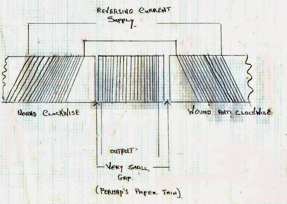

        Regards to all


        Ufopolitics
        Principles for the Development of a Complete Mind: Study the science of art. Study the art of science. Develop your senses- especially learn how to see. Realize that everything connects to everything else.― Leonardo da Vinci

        Comment


        • Originally posted by hanon1492 View Post
          Hi all,

          Just to clarify...because there are users which don´t follow this Figuera thread in deep and they are doing a mess with different patents.

          Mr. Figuera filed 5 patents: 4 of them in 1902, and the last one in 1908 few days before his death.

          Ufo is trying to replicate the patent from year 1902 No. 30376 which comprises a rotating copper winding with fixed and static exciter electromagnets

          There are also two patents about two designs for a motionless generator (patent No. 30378 from 1902 , and his last patent No. 44267 from 1908) where the induced coils are static and the exciter electromagnets are variable in strength. Please refer to this site for the whole list of documents: ( Link )

          In the 1908 patent it is required to feed both opposing electromagnets with two unphased signals. In Patrick Kelly´s book (chapter 3) it is described a circuit to acomplish this task which is really easy to build ( http://www.free-energy-info.tuks.nl/ ), but it has some little mistakes in the connections. Please see the scheme I have attached to this post for a correct configuration.

          Circuit to create the unphased signals

          I hope this help
          Hi all,

          This is a post to correct some errors in the circuit that I posted before. Please see the link to the file with the correct circuit to implement two unphased signals as defined in the 1908 Figuera´s patent.

          Circuit to create the unphased signals


          Regards
          Last edited by hanon1492; 09-23-2013, 09:57 PM. Reason: Edited on the 23rd of september to update the circuit in order to correct a mistake: pin 3 in the second CD4017 must not be used.
          https://figueragenerator.wordpress.com/

          Comment


          • Originally posted by Duncan View Post


            Hi Duncan,

            After studying your sketch with CW and CCW wirings, I have realized that you are placing like poles in front of each other in the inducer electromagnets. Am I right in my interpretation? Can you elaborate your proposal a bit deeper?

            Thanks in advance

            Regards
            https://figueragenerator.wordpress.com/

            Comment


            • Dear all,

              How about if N and S does not mean North and South in the 1908 patent notation?

              I had already noted that in the whole text of the 1908 patent there is no reference where it is explicitly stated that "N" means North and "S" South. In fact it is just written: " Suppose that electromagnets are represented by rectangles N and S. Between their poles is located the induced circuit represented by the line “y” (small). "

              Regards

              PS. Maybe it was just a patent notation trick
              Last edited by hanon1492; 01-10-2017, 01:19 AM.
              https://figueragenerator.wordpress.com/

              Comment


              • grist to the mill!

                No Hanon that’s not the picture I have at all … first keep in mind its pure iron .. no current = no (or little) residual magnetism .. each of the poles of the outside electromagnets are opposite (hence wound in different directions) curent flow and hence magnetic poles alter with the armature, however all the electrical side of the circuit sees is One inductance (one coil) … this can be made resonant with the source and frequency of the armature “or very nearly so” an so use very little “real power”. The centre electromagnet however will reverse polarity by induction and generate usable power in that winding which will not refect on the source. In fact if they were not big solid Iron Bars IMHO they could be bent into two horse shoe electromagnets .. with a keeper for the centre winding. (4x as much bang for your buck)
                and each would effectively become a Ed Leedskalnin PMH. The thing is Hanon the PMH it's self has long been viewed as static … that isn't quite true of magnetism there is a hidden dimension here its demonstrated with a PMH as it becomes dynamic.
                https://www.youtube.com/watch?v=L_2G28531sI and again here by magnet flipper
                Magnetic Vortex Spin Demonstration by Magnetflipper - YouTube
                considering those two outside windings … they could obviously be replaced by one Bifilar winding on a horse shoe yoke.
                so with this in mind I drew this


                which is basically your magnetic circuit .. but in a loop .. notice the gaps? This is how the steve Marks thing is working I believe.
                Steven Mark solid state generator video 1 - YouTube
                Any way in order to test the validity of both the Figuera magnetic circuit as well as the 3BGS I cut a toroid and wired it so. I fed the primary from a function gen … That of course is the Bifilar .. or in your case the two outside coils. I was monitoring the voltage output caused by the induced magnetic effect on the centre core. (thats the bottom trace) I didn't intend for open viewing .. still
                harmonics and overtones - YouTube
                I suspect that EL was quite right regarding electricity being split into two spirals and that's really what I was tracking here .. although it also demonstrates your circuit quite well …. I am playing betwixt 1Mhz and 3 Mhz with the function gen. Whilst nothing here is carved in stone I hope it adds a little bit of light to this project
                Last edited by Duncan; 08-18-2013, 10:56 AM.
                Whatever you can do,or dream you can,begin it.Boldness has genius,power and magic in it.Begin it now.

                Comment


                • Originally posted by hanon1492 View Post
                  Dear all,

                  In the Figuera forum into overunity.com an user had commented that in his opinion N and S does not mean North and South in the 1908 patent notation. See his post here:

                  IMO I do not think coils S,N,Y actually meen south and north pole faces. Studying the layout closely I think the Coils S and N are facing each other with the same sign pole faces.The need for seperate core pieces is so the field caused by the pulse "on" travels through the other two coils opposite (y+n)or (s+n)so the direction of induction on the center coil and the off coil are the same. Current is added back in series with the on impulse acting upon the off coil through the power source. So if the on impulse was 12 volts + the field would project through the two other core pieces and coils.The reaction on the center coil would act like half a sign wave be it up or down. The outer coil which is off would induce in reverse direction of it's on state at a lower voltage or amperage but would add to the source voltage in series.A clever way to use as much of the field as possible drawing in and using the lesser force on the far side of the induced coil used to power the load. Im not sure if enough current could be produced to remove the starting power source or not. The only way that could work is if there is unequal abillity of inducing a magnetic field in a core piece when comparing voltage to ampere. Meaning if I use 1 volt and 100 amp on a core will it be the same measure of gauss field as compared to 1 amp and 100 volts using identical cores and windings. So that the load could be used in part as a source once it is started even if that ment it has to be stepped up or down to add to the impulse field the strongest magnetic field that it can produce without taking away from the productitvity of operating the load.Boy that was a ***** to explain that thought.


                  I had already noted that in the whole text of the 1908 patent there is no reference where it is explicitly stated that "N" means north and "S" south. In fact it is just written: " Suppose that electromagnets are represented by rectangles N and S. Between their poles is located the induced circuit represented by the line “y” (small). "

                  Regards
                  Hi,
                  recently I got a hint from another thread to this one being dedicated to Figueras.
                  Reading your text above I hooked up a 3 phase transformer Figueras like and now I dare to chime in in order to report some observations.

                  Test A: Tested with single pulses.
                  I agree with the notion that energizing one outer coil will generate in center and opposite coil a voltage pulse in opposite direction.
                  BUT: The voltage is about 3 times higher in center coil than opposite coil. Some notions:

                  1.
                  Of course a 3 phase transformer has 3 identical limbs and the magnetic "resistance" is higher in outer limb because of more distance to travel

                  2. I tested at 400V windings with 24V pulses. Therefore we are possibly in lower nonlinear area of magnetic graph. So it is understandbale that center limb is preferred like having two sinks to drain water.
                  At higher flux or connected load it might be different.

                  3. The smaller center limb in Figueras patent might be tuned in order to balance for flux.

                  Test B: I connected:
                  • half rectified AC (positive half wave) to first outer coil
                  • half rectified AC (negative half wave) to outer coil but reverse electrical direction.

                  The trick is that both coils get flux pulses phase shifted and -> in same flux direction for center limb.
                  This - of course - is not what Figueras described for controlling coils.!

                  1.
                  Those 400V coils draw in this mode (half rectified) much more current than at true AC. They behave somehow like a DC electromagnet. (it was expected)
                  In this mode we need to have shorter pulses than 10 ms (reference. 50Hz regins) because flux will not go down considerably in center limb nor reverse. Hence it behaves like a flywheel being pulsed consecutively in same direction.
                  It seems taht in outer limbs flux reverses but I am not sure - I did not get the whole picture.

                  QustioN:
                  - Is there any hint or speculation on frequency at original setup?
                  - Is there any Spanish wording giving the abbreviations "N" "S"

                  2.
                  Center coil produces some very low power. At 250V AC input a 25W bulb (being connected to center coil) glowed very dim.

                  I'd like to note that any experiment gives new and valuable notions - even experiments being somehow off road like those described above. And even if they state what not to do!
                  If we are stumbling in fog we are glad for any piece of orientation we can get hold of.

                  HINT:
                  If somebody wants to tinker at a 3 phase transformer as well: Please get hold of one 400V/24V. At ebay there are plenty of them (ca. 100W....300W) Then you can isolate 400V contacts safely and work on 24V windings only.
                  This is my test object 26€ at eBay / about 15 x 15 cm front.
                  PLEASE DO NOT WORK ON MAINS VOLTAGES - as long you are not trained and equipped for these dangerous voltages!

                  Possible next steps:
                  • Cutting slots in center limb with angle grinder in order to balance flux flow (between center / opposite limb). I have the strong feeling Figueras secret has something to do with a special kind of balance - either for input flux, output (Lenz) flux or both.
                  • Building FET drivers along micro controller in order to simulate Figueras commutator. In another thread a FET driver was built and the PCB is available publicly now. (maximum ratings 100A / 600V - others call it Monster Driver )) I just started a turorial for building and testing it step by step.
                    This info might help some of you. And NO: I do not earn any penny or cent for it. All is public domain.


                  I will not begin seriously with Figueras replication soon because I am active in teh other thread. But I decided to share my ad hoc notions with all of you.


                  BTW:
                  - Magnetic field as vortes see Howard Johnson
                  - Magnetic amplifiers do the very same like usual amplifiers (ok they might introduce some math functions...) - they act as a valve on an energy flow. They do increase amplitudes of a certain value but not energy.
                  rgds
                  John Stone
                  Last edited by JohnStone; 08-18-2013, 07:45 PM.
                  Experts spend hours a day in order to question their doing while others stopped thinking feeling they were professionals.

                  Comment


                  • Like poles facing each other

                    Hi all,

                    About the discussion if like poles are facing each other in the 1908 Figuera patent I have thought in the next scheme:
                    .


                    John, about your question: "Is there any Spanish wording giving the abbreviations "N" "S"? ". The answer is that in spanish North is called "Norte" (N) and South is called "Sur" (S) , so N and S in spanish has the same meaning than in english.

                    My concern is that I have read again the 5 Buforn patents (copies of the 1908 original patent but filed after Figuera´s death) and in none of the 5 later patents from Buforn it is clearly stated the orientation of the N and S electromagnets...which is curious because you could think that in the last patents maybe Buforn could have clarified this important point instead of barely mentioning it. Buforn always wrote almost the same as Figuera about the N and S electromagnets: "Suppose that electromagnets are represented by rectangles N and S."

                    Studying this proposal more deeply I have also noted that in the patent text is written a sentence which match with the other forum user explanation that the current in the "OFF" coil adds to the input current in the "ON" coil. In the patent it is written: "As seen in the drawing the current, once that has made its function, returns to the generator where taken". Buforn also states that: "the current which crosses the magnetic field produced by the electromagnets, current which -after doing its function- returns to the origin where it has been taken". Buforn also states: " ....The electricity moves on the magnetic field and returns from it by the two opposite INLET and OUTLET sides of the resistor." (Buforn patent No. 57955, page 12; Year 1914)

                    Until now we were thinking that the resistor has only one way (current going into the electromagnets). Maybe we were mistaken and the resistor is a doble way path for the electricity to come into the "ON" coil, and to return after being induced in the "OFF" coil if like poles of the electromagnets are in front of each other ....

                    Please share your thoughts about this proposal.

                    Regards
                    Last edited by hanon1492; 08-18-2013, 09:36 PM. Reason: Corrections
                    https://figueragenerator.wordpress.com/

                    Comment


                    • Originally posted by JohnStone View Post
                      HINT:
                      If somebody wants to tinker at a 3 phase transformer as well: Please get hold of one 400V/24V. At ebay there are plenty of them (ca. 100W....300W) Then you can isolate 400V contacts safely and work on 24V windings only.
                      Hi John,

                      About your proposal for using 3 phase transformers I want to point that in the document posted by Wonju explaining his interpretation of Figuera´s generator the air gaps were the KEY part for the proper operation of this device. The air gap was used to canalize the induced b-field from the induce coil into the electromagnet which is at low value.

                      About the range of frequencies used there are no data about these values. But Figuera used in 1908 a simple rotary motor to induce the electromagnets, therefore I suppose that a high value around 3600 rpm (60 Hz) can be fine.

                      Regards
                      Last edited by hanon1492; 08-18-2013, 11:04 PM.
                      https://figueragenerator.wordpress.com/

                      Comment


                      • TRANSLATION OF KEY PARTS OF BUFORN PATENT No. 57955 (1914) (text extracted from pages 12,13 and 14)


                        By using a magnetic field, consisting of two series of electromagnets N and S, a resistor and a circumference of contacts isolated from each other .....

                        ...

                        Note that only the contacts located in the Northern semicircle are in communication with half of the end sides of each resistor, and the contacts in the Southern semicircunference are not in communication with the resistor, but respectively with the contacts in the semicircle communicated with half of the end sides of each resistor, and inasmuch as the current moves on the the magnetic field and returns from it by the input and output sides of the resistor, and as this field is composed of two series of electromagnets N and S , therefore, and as result of the operation of the device when the electromagnets N are full of current, the electromagnets S are empty, and as the current flowing through them is reducing or increasing in intensity according it passes by more or less turns of the resistor, and therefore, in continuous variation; since we have done a continuous and organized variation we have achieved a constant change in the current which crosses the magnetic field formed by the electromagnets N and S and whose current, after completing their task in the difrerent electromagnets, returns to the source where it was taken.

                        ...

                        We have already achieved to produce the continuous and organized change of the intensity of the current which crosses the magnetic field.

                        ....

                        The way to collect this current is so easy that it almost seems excused to explain it, because we will just have to interposed between each pair of electromagnets N and S, which we call inducers, another electromagnet, which we call induced, properly placed so that either both opposite sides of its core will be into hollows in the corresponding inducers and in contact with their respective cores, or either, being close the induced and inducer and in contact by their poles, but in no case it has to be any communication between the induced wire and the inducer wire.

                        ....

                        Another advantage is that around the core of the induced electromagnets we can put another small size induced electromagnet with equal or greater core length than the large induced one. In these second group of induced an electric current will be produced , as in the first group of induced, and this produced current will be sufficient for the consumption in the continuous excitation of the machine, being completely free all the other current produced by the first induced electromagnets in order to use it in all purposes you want.


                        --------------------------------------------------------------------------------------------------------
                        Original spanish text:

                        Valiéndose de un campo magnético, compuesto de dos series de electroimanes N y S, de una resistencia y de una circunferencia de contactos aislados uno de otro .....

                        ...

                        Hay que tener presente que unicamente están en comunicación las delgas de la semicincunferencia Norte con la mitad de los extremos de las partes de la resistencia y las de la semicircunferencia Sur no se comunican con la resistencia, sino respectivamente con las delgas de la semicircunferencia comunicadas con la mitad de los extremos de las espiras de la resistencia y además como quiera que la corriente pasa al campo magnético y vuelve del mismo por los extremos de entrada y salida de la resistencia y como este campo está constituido por dos series de electroimanes N y S, resulta que en virtud de lo expuesto y del funcionamiento del aparato, cuando los electroimanes N están llenos de corriente , los S, están vacíos y como la corriente que los atraviesa va aminorando o aumentando en intensidad según pase por mas o menos espiras de la resistencia, y por tanto en variación continua y puesto que esa función hemos logrado hacerla continua y ordenada habremos conseguido el cambio constante de la intensidad de la corriente que atraviesa el campo magnético formado por los electroimanes N y S y cuya corriente una vez cumplida su misión en los diferentes electroimanes vuelve al origen de donde se ha tomado.

                        ...

                        Hemos conseguido ya producir el cambio continuo y ordenado de la intensidad de la corriente que atraviesa el campo magnético.

                        ....

                        El modo de recoger esta corriente es tan facil que hasta parece excusado explicarlo; pues no tendremos más que intercalar entre cada par de electroimanes N y S, que llamaremos inductores, otro electroimán, que denominaremos inducido, de tal modo debidamente colocado que, o bien los extremos de su núcleo entre en el seno de los correspondientes inductores y en contacto con sus respectivos núcleos o bien aproximados inducido e inductor y en contacto por los polos, pero sin que en ningún caso haya comunicación alguna entre el devanado inducido y el devanado inductor.

                        ....

                        Además se puede aprovechar tambien el seno de los núcleos de los electroimanes inducidos en los que se puede colocar otro electroimán inducido de reducidas dimensiones y con igual o mayor longitud que el núcleo del inducido grande. En estos segundos inducidos, se producirá corriente eléctrica e industrial al mismo tiempo que en los primeros; y la corriente así producida podrá ser suficiente para el gasto de excitación continua de la máquina, quedando completamente libre toda la otra corriente producida por los primeros inducidos para dedicarla a toda clase de fines que se desee.

                        https://figueragenerator.wordpress.com/

                        Comment


                        • Is there any explanation about shape of commutator shaft ? I can't imagine how the contacts were made to efficently implement make before break schema.
                          Is there anything about the inducer coils connection in series ?
                          Why there is a box around the point of connection wire from commutator shaft to the power supply wire ?

                          Comment


                          • just a question

                            Hi folks, just started reading this thread ,am not up to speed.
                            In the diagram with the loose wires with multiple take-offs, is that some form of variable resistor?
                            That way changing the amount of current the electro-magnets receive causing flux intensity to change?
                            Just wondering, thanks
                            artv

                            Comment


                            • translation of bufon.pdf

                              Hi hanon,

                              I appreciate your great work on the forum.

                              Like Oliver I ask for more.

                              Is it possible to get the translation of the whole bufon document. I realize it is large doc maybe all that understands spanish in the forum could join forces.

                              Regards.

                              Comment


                              • Originally posted by boguslaw View Post
                                Why there is a box around the point of connection wire from commutator shaft to the power supply wire ?
                                VERY GOOD QUESTION !!! ????
                                https://figueragenerator.wordpress.com/

                                Comment

                                Working...
                                X