Announcement

Collapse
No announcement yet.

Re-Inventing The Wheel-Part1-Clemente_Figuera

Collapse
X
 
  • Filter
  • Time
  • Show
Clear All
new posts

  • theoreticians shut up

    Originally posted by hanon1492 View Post
    Hi all,

    The user Bajac at overunity.com (Wonju at EF) has achieved overunity with COP = 3 in his design of the Figuera generator. Follow this link to see the results:

    Results with COP = 3 (Figuera generator)

    There is still much work to do and to improve...

    Regards
    I hope this will shut up all the theoreticians on this thread.

    Comment


    • Originally posted by abdlquadri View Post
      I hope this will shut up all the theoreticians on this thread.
      If you don't see the problem with the power measurement in the PDF then, all well and good.

      It looks to me like the open circuit voltage was multiplied by the short circuit current to get the "output" power figures.

      Is that the correct way ? If so anyone can show any C.O.P.

      If anyone thinks that upsets anyone else they are wrong, just like the calculations.

      Cheers
      Attached Files
      Last edited by Farmhand; 01-23-2014, 02:31 PM.

      Comment


      • Farmhand,

        As Bajac states in his post into overunity.com he has 30 years of experience as electric engineer. I can assure you that he did make accurate test and calculations. The measurements are right, 100% sure . I don’t see your point in these forums: if someone propose a theory then you say that that theory sucks; if someone expose some EXPERIMENTAL results then you say that those result are not fine. Bajac has used a Thevenin circuit in order to have an accurate measure of the V and I values. He has even estimated the phase angle to calculate the right power output. As Bajac is not participating in this forum I recommend everyone to go the overunity.com forum and read Bajacīs own details about this extraordinary results with COP = 3

        From now we can say that Figueraīs generator has been tested to be overunity…. apart from being used in 1902 to give 15 HP as stated in many newspapers of that time.

        As commented previously the rest is history: Figuera sold the patent to some bankersīunion for about 230,000 $ ( referred to 1902), and then everything disappeared and went dark. Thatīs why we donīt have Figueraīs generators in our houses today.

        Keep the faith!!
        https://figueragenerator.wordpress.com/

        Comment


        • Congratulations to Wonju Bajac

          Originally posted by hanon1492 View Post
          Hi all,

          The user Bajac at overunity.com (Wonju at EF) has achieved overunity with COP = 3 in his design of the Figuera generator. Follow this link to see the results:

          Results with COP = 3 (Figuera generator)

          There is still much work to do and to improve...

          Regards

          Hello Hanon,

          Those are great news friend!...I am pretty sure He will soon make more convincing testing with a closed looped load at output or secondaries...measuring the two simple parameters...V & I...

          What I find very useful and fascinating is the fact of how much difference it could make on Output, by reducing the air gap in such small differences (from 0.6 to 0.1!) He call it "Paper Thin Gap"...and I imagine the core faces must be extremely well machined and smoothed down in order to maintain this same gap evenly through the whole core.

          Hanon, could you please post here the Circuit Diagram and Spec's of what He has built...I mean His, not the Figuera Patent...as well as its 555 timer pulser...many thanks friend.


          I really do not like OU.com to post and follow there...its full of advertisement ...and noises.


          Regards


          Ufopolitics
          Principles for the Development of a Complete Mind: Study the science of art. Study the art of science. Develop your senses- especially learn how to see. Realize that everything connects to everything else.― Leonardo da Vinci

          Comment


          • Originally posted by hanon1492 View Post
            Farmhand,

            As Bajac states in his post into overunity.com he has 30 years of experience as electric engineer. I can assure you that he did make accurate test and calculations. The measurements are right, 100% sure . I don’t see your point in these forums: if someone propose a theory then you say that that theory sucks; if someone expose some EXPERIMENTAL results then you say that those result are not fine. Bajac has used a Thevenin circuit in order to have an accurate measure of the V and I values. He has even estimated the phase angle to calculate the right power output. As Bajac is not participating in this forum I recommend everyone to go the overunity.com forum and read Bajacīs own details about this extraordinary results with COP = 3

            From now we can say that Figueraīs generator has been tested to be overunity…. apart from being used in 1902 to give 15 HP as stated in many newspapers of that time.

            As commented previously the rest is history: Figuera sold the patent to some bankersīunion for about 230,000 $ ( referred to 1902), and then everything disappeared and went dark. Thatīs why we donīt have Figueraīs generators in our houses today.

            Keep the faith!!
            No one needs to be an engineer to know that multiplying the open circuit
            voltage by the short circuit current gives a figure that means next to nothing.

            Is there no explanation of why doing that is ok.

            Please explain. How can multiplying the open circuit (unloaded) voltage by the
            short circuit current (shorted) mean anything ?

            As I said if no one cares neither do I but I can still mention it if I want.

            Maybe I should show some measurements like that and claim over unity as
            well, but to what end ?

            Using those measurement methods I can probably show a C.O.P. of 100 or more.

            I disagree with your generalization of my activities.

            if someone propose a theory then you say that that theory sucks; if someone expose some EXPERIMENTAL results then you say that those result are not fine
            Cheers

            P.S. Time tells all truth. We will see.

            You think I do not know any engineers ?

            I don't think the Thevenin's Theorem applies in such a situation.

            Thevenin's Theorem

            Thevenin's Theorem

            Any combination of batteries and resistances with two terminals can be replaced by a single voltage source e and a single series resistor r. The value of e is the open circuit voltage at the terminals, and the value of r is e divided by the current with the terminals short circuited.
            No battery in the output circuit.

            Thevenin Voltage

            The Thevenin voltage e used in Thevenin's Theorem is an ideal voltage source equal to the open circuit voltage at the terminals. In the example below, the resistance R2 does not affect this voltage and the resistances R1 and R3 form a voltage divider, giving
            The voltage is far from an ideal voltage source.
            ..

            The actual power dissipated by those short circuits can be calculated, but more info is needed, I think.
            ..

            But people can ascribe to anything they please, as I have the right to
            comment on an open forum in a civil manner on a relevant topic of some
            importance to how others perceive the results shown.

            No one needs believe me.

            AC Thevenin's Theorem

            Any combination of sinusoidal AC sources and impedances with two terminals can be replaced by a single voltage source e and a single series impedance z. The value of e is the open circuit voltage at the terminals, and the value of z is e divided by the current with the terminals short circuited. In this case, that impedance evaluation involves a series-parallel combination.
            ..

            Anyway aside from if the Theorem is correct to use, a short circuit is not
            output, so there is no C.O.P. unless the heating of the thing is wanted.

            ..
            Last edited by Farmhand; 01-24-2014, 08:03 AM.

            Comment


            • Well that was easy, using the same method as the results shown here I
              measured (on the scope) 100 VAC open circuit and 150 mA short circuit current
              from the secondary of a small transformer while the input went from 300 mA
              at 12.3 volts unloaded to 400 mA at 12.3 volts with the secondary short circuited.

              That works out using the same calculations to be.

              Input open - 3.69 Watts
              Input loaded - 4.92 Watts

              Output open - 100 VAC
              Output short circuited - 150 mA

              So then if we multiply the open circuit voltage by the short circuit current we get a figure of 15 Watts.

              Input 4.92 Watts - "dissipated" 15 Watts. = "C.O.P. of 3.04" Easy.

              However I know this is incorrect.

              Cheers

              I can also measure power at 7 times the input power that is oscillating in a
              tank on the secondary but that is not output either. So no output no C.O.P..

              ..
              Last edited by Farmhand; 01-24-2014, 09:14 AM.

              Comment


              • here UFO .. see if this clicks for you!

                I am really writing this directly to UFO politics not out of disrespect to any of you guys but because I know he has ploughed through the big bang thread and understood it ! It should come as no surprise to anyone that viable COP>1 machines are going to have common cause how could it be otherwise ? After all if your a gambling man what's the chances of hiding a much needed energy source from man kind for well over a hundred years ? Yet its been done ! If you don't believe there is such a source like Farmhand for instance and I don't blame him, then the answer is obviously infinite . Well some folks know there is such a source against all the odds . However what chances are there of being two or three different sources remaining hidden ? Infinity squared and cubed ? I hardly think so do you ? Ergo every viable machine is using the same source one way or another. Well UFO politics you have read through the Christmas card … and the big bang post and I thank you for that! I would just like to remind you how that kicked off
                with a Christmas card ...This Card


                I need to point out here UFO that core and coil A or B could be missed out , It would not be quite as efficient but never the less would still function (providing of course it was running at series resonance if you remember. as VI cos θ is close to zero and no real power is consumed .
                It also goes without saying that this machine must be run with a LA battery, as that itself is a reactive machine.

                Capacitive Battery Charger - John Saves Energy)

                This is what has occurred with this machine of Figuera's. I have tried several times to project this onto this thread I have failed miserably. I am rather hoping as you grasped the principle above you'll be able to grasp this connection and then see what I see and perhaps explain it better than I have been able to.

                UFO if you regard the Figuera drawing below Notice I have added Iron loop D to the last segment … that could be equally applied to all of the sections. It would make the machine more efficient .. but its not essential.


                I have then labelled the cores and windings A,B.C and D which in turn corresponds with My Christmas card , which in turn is my interpretation of the Steve Mark Toroid which you seem to have got hold of OK and that in turn ties to this

                http://www.energeticforum.com/renewa...tml#post249217

                of course in this era the armature of a DC motor is used as an interrupter .. to provide the impulse waveform. Where as I am using an H bridge to perform the same operation.
                Figuera has not used a toroid as Steve Mark has done , after all he's using magnetically soft Iron Bars . (as I am ) not easy to get into a circle! So if you can grasp that UFO please tell the others because I have tried and better tried and I can't prevail .
                Here tied together is Steve Marks TPU , Edward Leedskalnin's generator , my own Christmas card . And Anguswangus reverse lenz effect. Those air gaps are obviously nothing to do with reluctance and all that tosh … the magnetism is induced it is reversing the polarity of cores 'y' that is the all important object. If the air gaps were a 'machine fit' far better still!
                I hope you can make this connection for these guys UFO I drew that core pages and pages ago it made no impression then .. I doubt it will now. Still one can but try! (so I do) and I'll keep trying. because .. we have common cause!
                Last edited by Duncan; 01-24-2014, 01:37 PM.
                Whatever you can do,or dream you can,begin it.Boldness has genius,power and magic in it.Begin it now.

                Comment


                • Hanon1492,

                  I have over 50 years of hands on work in electronics. Someone being an engineer does not impress me. I have worked with some of the very best in this country and also some of the very worse. A lot of electrical engineers don't even know how to properly use a meter. They are usually pretty good on theory but not the practical side of things.

                  Farmhand is totally correct that the way the output power was calculated is wrong. This is the same mistake Don Smith made when he claimed a neon sign transformer was OU. To properly calculate the output power you have to have some kind of load on the output and measure both the current and voltage at the same time. Measuring open circuit voltage and short circuit current means nothing.

                  As I have said many times on this forum I do believe OU may be possible and there are some projects on this forum that appear to have some potential for doing that. I think this project may have that possibility. But we have to be careful that we are not just fooling ourselves with poor measurements and lack of knowledge as to how things should be done. Also throwing out words like the Thevenin circuit does't help matters at all. As soon as I saw that I realized something was wrong as the Thevenin analysis does not apply to this measurement process.

                  Originally posted by hanon1492 View Post
                  Farmhand,

                  As Bajac states in his post into overunity.com he has 30 years of experience as electric engineer. I can assure you that he did make accurate test and calculations. The measurements are right, 100% sure . I don’t see your point in these forums: if someone propose a theory then you say that that theory sucks; if someone expose some EXPERIMENTAL results then you say that those result are not fine. Bajac has used a Thevenin circuit in order to have an accurate measure of the V and I values. He has even estimated the phase angle to calculate the right power output. As Bajac is not participating in this forum I recommend everyone to go the overunity.com forum and read Bajacīs own details about this extraordinary results with COP = 3

                  From now we can say that Figueraīs generator has been tested to be overunity…. apart from being used in 1902 to give 15 HP as stated in many newspapers of that time.

                  As commented previously the rest is history: Figuera sold the patent to some bankersīunion for about 230,000 $ ( referred to 1902), and then everything disappeared and went dark. Thatīs why we donīt have Figueraīs generators in our houses today.

                  Keep the faith!!
                  Respectfully, Carroll
                  Just because someone disagrees with you does NOT make them your enemy. We can disagree without attacking someone.

                  Comment


                  • I must admit there is some dubious instrumentation here and there. Carroll Seemed to me at one stage as I was watching that Anguswangus thing the guy seemed to measure voltage across a coil changed the instrument to current and then just stuck it straight across the same coil .
                    Quite what he thought he was showing I'm none to sure! Not a good technique to develop for testing the mains I know that much! still I'm sure his hearts in the right place!
                    Whatever you can do,or dream you can,begin it.Boldness has genius,power and magic in it.Begin it now.

                    Comment


                    • Thanks Duncan

                      Originally posted by Duncan View Post
                      I am really writing this directly to UFO politics not out of disrespect to any of you guys but because I know he has ploughed through the big bang thread and understood it ! It should come as no surprise to anyone that viable COP>1 machines are going to have common cause how could it be otherwise ? After all if your a gambling man what's the chances of hiding a much needed energy source from man kind for well over a hundred years ? Yet its been done ! If you don't believe there is such a source like Farmhand for instance and I don't blame him, then the answer is obviously infinite . Well some folks know there is such a source against all the odds . However what chances are there of being two or three different sources remaining hidden ? Infinity squared and cubed ? I hardly think so do you ? Ergo every viable machine is using the same source one way or another. Well UFO politics you have read through the Christmas card … and the big bang post and I thank you for that! I would just like to remind you how that kicked off
                      with a Christmas card ...This Card


                      I need to point out here UFO that core and coil A or B could be missed out , It would not be quite as efficient but never the less would still function (providing of course it was running at series resonance if you remember. as VI cos θ is close to zero and no real power is consumed .
                      It also goes without saying that this machine must be run with a LA battery, as that itself is a reactive machine.

                      Capacitive Battery Charger - John Saves Energy)

                      This is what has occurred with this machine of Figuera's. I have tried several times to project this onto this thread I have failed miserably. I am rather hoping as you grasped the principle above you'll be able to grasp this connection and then see what I see and perhaps explain it better than I have been able to.

                      UFO if you regard the Figuera drawing below Notice I have added Iron loop D to the last segment … that could be equally applied to all of the sections. It would make the machine more efficient .. but its not essential.


                      I have then labelled the cores and windings A,B.C and D which in turn corresponds with My Christmas card , which in turn is my interpretation of the Steve Mark Toroid which you seem to have got hold of OK and that in turn ties to this

                      http://www.energeticforum.com/renewa...tml#post249217

                      of course in this era the armature of a DC motor is used as an interrupter .. to provide the impulse waveform. Where as I am using an H bridge to perform the same operation.
                      Figuera has not used a toroid as Steve Mark has done , after all he's using magnetically soft Iron Bars . (as I am ) not easy to get into a circle! So if you can grasp that UFO please tell the others because I have tried and better tried and I can't prevail .
                      Here tied together is Steve Marks TPU , Edward Leedskalnin's generator , my own Christmas card . And Anguswangus reverse lenz effect. Those air gaps are obviously nothing to do with reluctance and all that tosh … the magnetism is induced it is reversing the polarity of cores 'y' that is the all important object. If the air gaps were a 'machine fit' far better still!
                      I hope you can make this connection for these guys UFO I drew that core pages and pages ago it made no impression then .. I doubt it will now. Still one can but try! (so I do) and I'll keep trying. because .. we have common cause!

                      Hello Duncan and Thanks for your kind words.

                      I am sure of all this possibilities/Machines are VERY real, they were and they are...that's beyond doubt.

                      What I see along all this time...we all have been making mistakes so far..by disregarding, not paying much attention to the magnetic fields...while dedicating great time and development to the controllers/oscillators and coils shapes etc...

                      Tesla, Steve Marks...like DR T Henry Moray, Tariel Kapanadze...and many others had already found the sweet spot between dynamic and static fields, and I believe the key is exactly right there. Now, it would be understood that once we find the right elements, materials, the right alignments, the right oscillations, the proper wire gauge,etc,etc...then it is just a matter to "turn the switch On"...and the Energy starts to flow.

                      Now, analyzing Steven Mark...one of his videos...like:

                      Free energy TPU Demonstration (Steve Marks) - YouTube

                      Stop right at minute 0.25...and look at the huge Transformer where He connects Appliances...what do you guys see right in front of Transformer?

                      I see some parallel aligned plates...and even though video quality is very poor...you could see the Two transverse bars keeping the distance evenly between plates...

                      To me...that is a Variable Capacitor...a pretty well sized one...The Parallel Plates we see with the two bars is the Stator...and there is another angle at video where you could see the rotor plates, but pretty blurry...the Dial is all black out...but is there at center of outer blk face plate...maybe am wrong...please correct me if so.

                      They could be Heat sinks?...what for?...if so they were supposed to be mounted on Transformer Frame...and not separately positioned in front... or they could house Transistors in charge to create the oscillations?

                      For the demonstration, Marks do not need to start dialing capacitance...He already have it "nailed"...what he does need to "tune" is the Toroid Magnetic Field.

                      I do believe in the Air Gap variation as a very important issue Duncan...I believe the Air Gap is doing nothing more than varying the magnetic field spectrum and setting it in a way that it becomes that "Star Gate" we all are looking for...just like in a motor works more robust/stronger the shorter air gap between stator and rotor would be.

                      Now, Wonju/Bajac speaks of making "overlapped cores" in order to reduce even more the air gaps...do you know what he means?

                      I believe he means to "Interlace" Laminations from both cores at interaction...just like a Variable Condenser plates enter between each others space but NEVER touch between them.

                      Relating to your Toroid in the Christmas Card...that looks awesome...and see, I do not care about a poor drawing...I can see beyond that and I could see it perfectly well "painted" with even a smooth gradient of nice colors in the background...
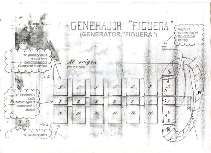
...But technically speaking, I believe we are missing something there...Air Gaps between attracting N/S Poles...Now, how could you do that and still maintain toroid as a single strong volume?...simple...adjusting bolts/nuts/brackets between frames sections ,Dividing the Quadrant in exactly Four "(" Pieces...just slide a piece of very thin paper as a gap gauge...and tighten bolts, then slide paper...done.

                      I have done many experiments with solid state coils, air core...I have inserted two big round "bullet like" long bolts...and while pulsing coil...at low hertz...I hold both steel bolts with my hands and get them as close as possible...have any of you tried that?...well, the point is...the MASSIVE STRENGTH that you can feel is going on at those gaps...it is amazing...and while attached and vibrating...try to break them apart...you simply can NOT do it...and yet, they are NOT LOCKED/STUCK Steel to Steel...you DO feel that Air Gap there friend...

                      LIGHTING HID BULB ASSY WITH RADIANT ENERGY - YouTube

                      On Video above, when pulsing on Air Core...I show this Bullet Steel Bolts (just one here)...

                      So, yes, like I have posted on your great Thread...I believe the key is in creating both Fields to be "adjustable", Static (Capacitive) and Dynamic (Magnetic), first from a Mechanical approach...then, once we hit the right, sweet resonance spot...we lock them in...clear coat the gaps...and tight seal the plates dials...we are done...it may take a long time of playing to achieve between millions of possibilities...but somebody will definitively hit the spot...sooner or later...just like this great guys did before.

                      We should recognize there is no electronic component the same exact spec's...as also not same steel alloy or laminations are exempt of errors...of unequal molecular balance...so, this means every set would be a different number...the key number...but, I believe they should "linger" around same spaces if we replicate them as close as possible from the 3D Model structure...


                      My Two Cents...

                      Thanks again Duncan!


                      Ufopolitics
                      Last edited by Ufopolitics; 01-24-2014, 05:47 PM.
                      Principles for the Development of a Complete Mind: Study the science of art. Study the art of science. Develop your senses- especially learn how to see. Realize that everything connects to everything else.― Leonardo da Vinci

                      Comment


                      • Duncan,

                        Your device is very different to Figuera generator. You state that your device require high frequency to run, maybe KHz or MHz and also require to be tuned for series resonance. Figura used a motor to drive his commutator so he should have worked at 50 Hz or less. Also there is no reference to any capacitor to get into resonance.

                        I think Figuera based his generator on a way to get the wires cut by the lines of force in a motionless machine.
                        https://figueragenerator.wordpress.com/

                        Comment


                        • Bigs news are ocurring into overunity.com forum. Go there and have a look if you are really interested in Figuera device
                          https://figueragenerator.wordpress.com/

                          Comment


                          • Originally posted by hanon1492 View Post
                            Bigs news are ocurring into overunity.com forum. Go there and have a look if you are really interested in Figuera device
                            Please give a link to the thread you are speaking of . Thanks
                            William Reed

                            Comment


                            • I believe this link will take you to curretn page.

                              Re-Inventing The Wheel-Part1-Clemente_Figuera-THE INFINITE ENERGY MACHINE

                              Bob

                              I think overunity.com has changed their forum software lately. It takes me atleast 60 seconds or more for the comments to load, and instead of starting at the top of the page, it starts at the newest post. This is a little annoying to have to wait so long, but it will eventually load.
                              Bob
                              Last edited by RMatt; 02-23-2014, 05:28 AM.

                              Comment


                              • Info from a guy who built a successful Figuera generator

                                Hi all,

                                I am sharing some info that was not released previously. If you have followed the forum from the beginning a spanish guy posted in some websites that he had replicated the generator successfully. I could get his email address and I contacted him by email and he wrote me many times. Unfortunately he did not disclose the exact system but he preferred to write about concepts and analogies. I did what he suggested but I could not have success. Now I am releasing in the attached pdf all the info that that guy sent me (I promised him not to reveal his email). Suddently he stopped sending more emails, so I think he thought that there were enough info in those emails. He said that he used as input 12 volts and 3 Amps and he got as output around 3500 W. I think that he did not test all that he described, I suppose that he jsut had a simple coil system, so please, take that info with much care and disect from it just the important ideas.

                                I post here all this info. Maybe someone could get any idea about this prototype. I couldnīt because the info is very contradictory. You can use Google Translator to get the text into english.

                                I hope it will help. I uploaded it in an external link because it is 5.5 MB

                                Regards

                                Link to view the pdf file

                                Link to download the pdf file directly

                                Good Luck. I really hope someone could do it soon !!

                                This project is more continuously updates into overunity dot com forum. I recommend you to follow it there.
                                Last edited by hanon1492; 03-24-2014, 12:00 PM. Reason: Added title
                                https://figueragenerator.wordpress.com/

                                Comment

                                Working...
                                X