 Tweet
Tweet
Originally posted by bistander
View Post
I knew my answer will trigger some "BEMF"...

Ok, what I meant (related to Classic Explanation) you all know how it goes...right?
And, yes, I meant "Current TRIES to keep being CONSTANT, while Voltage REVERSES".
Now, IF Coil has been completely disconnected it means no further supply of either voltage nor current would be available. So, this means that no matter how much current "attempts" or "tries" to keep a Constant Value, it could not be possible to maintain this constant through time...Then it means current will have absolutely no other recourse but to start falling down as originated magnetic field collapses.
Now, related to "Reversal" versus "Constant" meanings...
Reversal is not the opposite of constant, it does not say so in the link you've cited. That link only tries to explain what a reversal is.
For example: A Current VALUE could keep being CONSTANT (The Same Amp Value), while it COULD change directions, therefore, Current REVERSES and its value remains CONSTANT
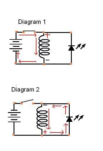
Let's say a Constant I = 1 Amp and a swapping Voltage from plus to minus Signal (in a Square Wave like shown below) is fed to a Coil:
[IMG]
 [/IMG]
That Coil is receiving a V Reversal over time, while Current Value is constant...this means this Coil is swapping Magnetic Fields Polarities over time as well.
Now, how do you think Current behaves here during Up-Down V Cycles?
And by the way...I am making that video related to the CRT Imaging Magnetic Fields...so, that is why I have been away from posting...but am almost done, so get ready...
Ufopolitics

 ...OR the fact you were doing it Over the speed limit at a CONSTANT Violation of 15 extra MPH?


Comment