 Tweet
Tweet
Five Steps Advance Angles Video...
[VIDEO]https://www.youtube.com/watch?v=st6ygKoAzYY[/VIDEO]
IMPERIAL FIVE STEPS ADVANCING ANGLES
[VIDEO]https://www.youtube.com/watch?v=st6ygKoAzYY[/VIDEO]
IMPERIAL FIVE STEPS ADVANCING ANGLES
 [/IMG]
 [/IMG]
 [/IMG]
 [/IMG]
 [/IMG]
 [/IMG][/IMG][/IMG]
 [/IMG]
 [/IMG]
 [/IMG]
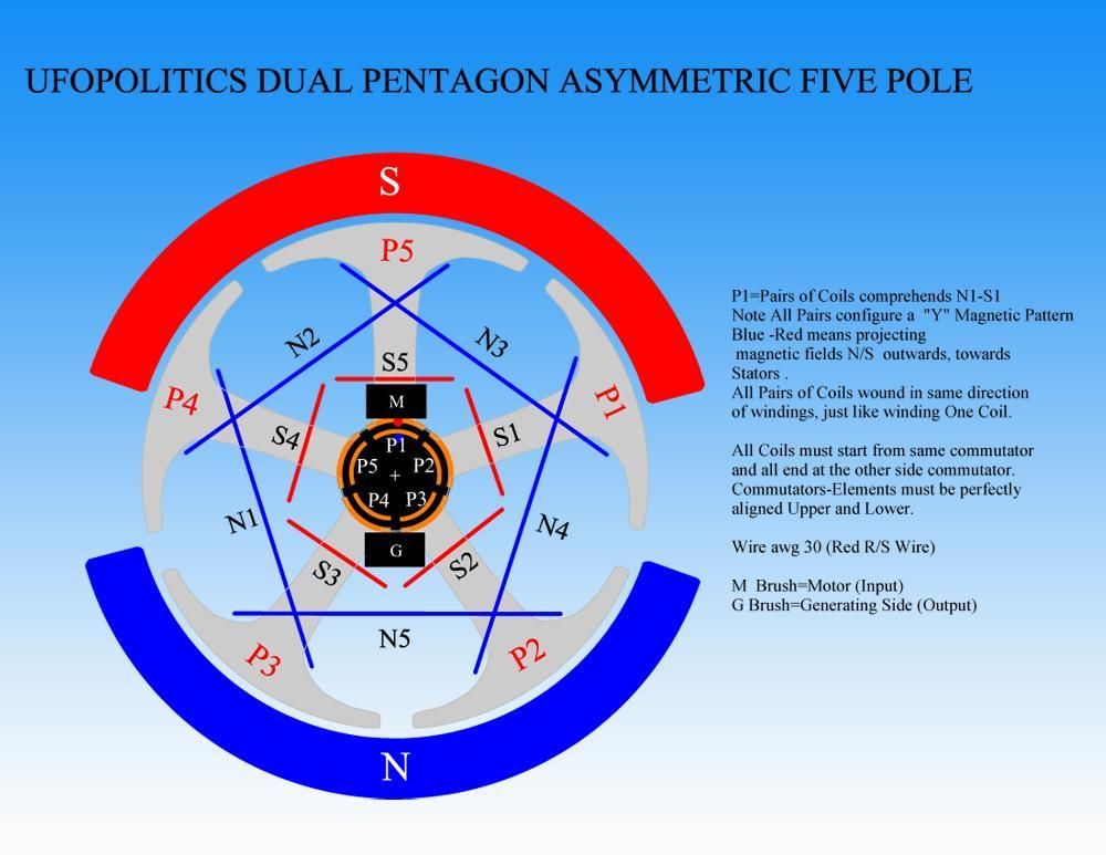
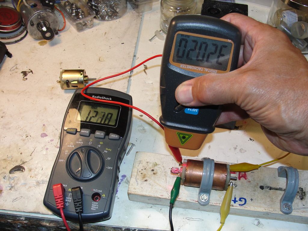

 , well then, that opens a design possibility where these little motors could be designed a little like the forklift motors, say a much lower coil resistance around .1 ohm, not 1 ohm, if my logic is correct. This motor would of course be some kind of monster
 !!!! RPM??? Motor stresses could be incredible. 12v might be too much... Or never run it unloaded !!
Comment