 Tweet
Tweet
It wasn't my intention to post further on this topic but I promised to wait a few days after my comments have been misrepresented.
I will not dilute my point by picking apart UFO's interpretation of what I have said and drawn on this topic. Suffice to say that interpretation is wrong.
I will reinforce what I have said firstly by thanking Jeffy for correctly stating my point and thereby assisting UFO in creating the 5 frame film strip. Which I agree with and this does represent what I have been saying.
And secondly I have uploaded another graphic to further reinforce the following paragraphs.
There are fixed parameters in our motors and there are variable parameters.
Fixed being -
1) Stator Bisectors
2) Comm Segment Width
3) Brush Width
4) Number of Poles and therefore Pole angle
5) Choice of Coil Structure (pairs or groups) establishes the Coil Bisector Angle. That is the angle between the first coil and final coil bisector
Variable being -
6) The 'sweep angle' or 'time on the brush' where the comm segment sweeps over the brush.
For Single Coil and First Coil Pairs or Groups, we set the bisector at 5� past the North Stator Bisector (NSB) as the 'ON' time. This means that ALL coil structures attached to that connected comm segment are also 'ON'.
For Pairs and Groups the Final Coil extends towards the South Stator Bisector (SSB) by an angle dependant on the chosen wind. For the image below I have used a Coil Bisector Angle of 120� which would represent a '4 Pole Pair' on a 12 Pole motor.
The discussion on this particular aspect of winding, for me, was to estimate when P2 coils are 'OFF' so as to avoid the P2 'ON' coils bisector being within 20� of the SSB or possibly even past the SSB. This scenario will cause a drop in efficiency of the chosen wind.
It becomes obvious when considering the mechanics of this, that one can consider the P2 'OFF' angle from when P1 just attaches to the brush, OR better still, just calculate it from the P1 'sweep angle' as it connects and disconnects from the brush.
It is clear that the angle of ONE comm segment 'sweeping the brush' is the angle that the Final Coil Bisector advances towards the SSB from connection to disconnection. There is only ONE SWEEP ANGLE for a motor and it is a direct function of the OEM motor given by the width of the comm segment and the brush width in degrees.
The image below, as before, indicates the comm segment is just 'ON' by 1� and 'sweeps' for 57� where it is 0� 'OFF'. It indicates where a Single Coil will be 'OFF' after 57� and it indicates where the Final Coil of a Pair or Group will be 'OFF' after 57�. For a 12 pole 4 pole Pair wind, we can see it passes the SSB and is unsatisfactory for 12 pole motors.
[IMG]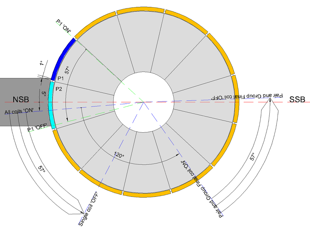 [/IMG]
Happy Hunting
mark
I will not dilute my point by picking apart UFO's interpretation of what I have said and drawn on this topic. Suffice to say that interpretation is wrong.
I will reinforce what I have said firstly by thanking Jeffy for correctly stating my point and thereby assisting UFO in creating the 5 frame film strip. Which I agree with and this does represent what I have been saying.
And secondly I have uploaded another graphic to further reinforce the following paragraphs.
There are fixed parameters in our motors and there are variable parameters.
Fixed being -
1) Stator Bisectors
2) Comm Segment Width
3) Brush Width
4) Number of Poles and therefore Pole angle
5) Choice of Coil Structure (pairs or groups) establishes the Coil Bisector Angle. That is the angle between the first coil and final coil bisector
Variable being -
6) The 'sweep angle' or 'time on the brush' where the comm segment sweeps over the brush.
For Single Coil and First Coil Pairs or Groups, we set the bisector at 5� past the North Stator Bisector (NSB) as the 'ON' time. This means that ALL coil structures attached to that connected comm segment are also 'ON'.
For Pairs and Groups the Final Coil extends towards the South Stator Bisector (SSB) by an angle dependant on the chosen wind. For the image below I have used a Coil Bisector Angle of 120� which would represent a '4 Pole Pair' on a 12 Pole motor.
The discussion on this particular aspect of winding, for me, was to estimate when P2 coils are 'OFF' so as to avoid the P2 'ON' coils bisector being within 20� of the SSB or possibly even past the SSB. This scenario will cause a drop in efficiency of the chosen wind.
It becomes obvious when considering the mechanics of this, that one can consider the P2 'OFF' angle from when P1 just attaches to the brush, OR better still, just calculate it from the P1 'sweep angle' as it connects and disconnects from the brush.
It is clear that the angle of ONE comm segment 'sweeping the brush' is the angle that the Final Coil Bisector advances towards the SSB from connection to disconnection. There is only ONE SWEEP ANGLE for a motor and it is a direct function of the OEM motor given by the width of the comm segment and the brush width in degrees.
The image below, as before, indicates the comm segment is just 'ON' by 1� and 'sweeps' for 57� where it is 0� 'OFF'. It indicates where a Single Coil will be 'OFF' after 57� and it indicates where the Final Coil of a Pair or Group will be 'OFF' after 57�. For a 12 pole 4 pole Pair wind, we can see it passes the SSB and is unsatisfactory for 12 pole motors.
[IMG]
 [/IMG]
Happy Hunting
mark


Comment