Announcement

Collapse
No announcement yet.

My Asymmetric Electrodynamic Machines

Collapse
X
 
  • Filter
  • Time
  • Show
Clear All
new posts

  • Originally posted by Ufopolitics View Post
    I know all you have written above. I know you could make an electromagnet the size of a Mansion as well.

    I know electromagnets are used to "stamp" the magnetic field within the ceramic mass.

    I was referring at the limited space within a motor armature-structure or within a Stator Housing that we all have in order to wind-build a coil and therefore...vualá...we made the "Electromagnet".
    Realize the units of Tesla (flux density) refer to Webers/square meter (flux per unit area). Therefore size doesn't matter. The electromagnet can be stronger than a permanent magnet whether it is on the cm scale or the m scale or the km scale. The most torque dense motors (attributing to flux and current) are wound field motors, not PM motors. Namely the series wound DC and the switched reluctance motors.

    bi

    Comment


    • Originally posted by Ufopolitics View Post
      The wires from Pair Coils to be attached to Commutator Elements-Brushes...I could flex, pull, stretch, Turn them left or right...up or down and connect them wherever I please to do...within interacting angles, or away by 10, 20, 50 100 degrees...it DOES NOT MATTER...that is just an ON-OFF Switching...as a matter of fact one could be in Japan, while the other one in Ireland...don´t care....or be Remote Control by all means...it does NOT ADD NOR SUBTRACT to the REAL MAGNETIC INTERACTIONS taking place.
      ---S---

      Originally posted by Ufopolitics View Post
      The point in this whole deal above...is that the Brush positioning DOES Matter, basically if we are overlooking the 3D Alignment planes.

      Second: The position of Brushes, related to Stators Bisectors is our only way to adjust timing. It could be the other way around...meaning moving Stators related to brushes...but...who is gonna do that with fixed magnets structure?...or in bigger size motors like Imperial?

      Now, Mark, getting back at your statement, brushes positioning not important?...I really can not understand how could you state that...since it is the ONLY means We have to set the timing?
      @UFO

      You have introduced a whole new level of complexity to the discussion which I had deliberately avoided under the title of 'fine detail'. Until now I have only discussed the broad principles and briefly alluded to some points that need to be considered under that title of 'fine'.

      If I'm understanding this correctly, you have also changed the terms of reference. We had previously agreed that the brushes could be in Japan and Ireland because the position is not important and now positioning DOES Matter.

      So let me put 'position' in context so that we can agree. The brushes can be anywhere in the region of 360° including Japan and Ireland if necessary so long as they give us our critical ON and OFF angles. After we take away all the 'detail' the remaining angle represents our timing adjustment. This could be a few degrees either side of Japan and Ireland, it doesn't really matter...because it's relative. The fine positioning is our timing and is relative to the broad positioning which can be anywhere. We both know we could turn to CAD schematics right now and prove that principle with ease.

      The misalignments you are now discussing are the very reasons why I adopted the double comm build that I did...and explained this at the time. The ability for new builders to achieve this level of accuracy on the kitchen table without the correct equipment is a matter of degrees more difficult. It is why I eventually pursued the single comm build because it allows a new builder to perfect the build and avoid focusing on misalignment issues. The single comm is always aligned.

      So I'm a little mystified why you have introduced misalignment issues to this discussion. First of all we should assume perfect alignment as a prerequisite for debate. The thing new builders have to understand is that on a 28 pole motor for example, it doesn't take a lot of misalignment to mean that there are never 2 comm segments energised at the same time. That would be a pretty incompetent build, but it's not beyond the wit of man to understand.

      Can we get to a position where there is one categoric statement on a perfectly aligned motor that concludes the time on the brush (sweep angle or any other term we care to adopt) is critical in the calculation of motor timing ?

      Keep Hunting

      mark

      Comment


      • Originally posted by HuntingRoss View Post
        ---S---

        @UFO

        You have introduced a whole new level of complexity to the discussion which I had deliberately avoided under the title of 'fine detail'. Until now I have only discussed the broad principles and briefly alluded to some points that need to be considered under that title of 'fine'.

        If I'm understanding this correctly, you have also changed the terms of reference. We had previously agreed that the brushes could be in Japan and Ireland because the position is not important and now positioning DOES Matter.


        Keep Hunting

        mark

        The wires from Pair Coils to be attached to Commutator Elements-Brushes...I could flex, pull, stretch, Turn them left or right...up or down and connect them wherever I please to do...within interacting angles, or away by 10, 20, 50 100 degrees...it DOES NOT MATTER...that is just an ON-OFF Switching...as a matter of fact one (Understanding "One" as "SWITCH ASSY" NOT JUST "THE BRUSH" Positioning) could be in Japan, while the other one in Ireland...don´t care....or be Remote Control by all means...it does NOT ADD NOR SUBTRACT to the REAL MAGNETIC INTERACTIONS taking place.
        Mark, after your response above related to Ireland and Japan and just Brushes positioning...I've realized we both have a very serious problem in understanding each others.

        I have highlighted the important part of my paragraph where I mentioned that...take a look at it again...

        I am talking about the whole switch assembly that could be anywhere you wanted. And, that switch assembly includes the brushes, BUT as well as the other part of the switch, the contacts...or, in this case the Commutator Elements and, of course the wires terminals that come from each independent coils.

        There is a HUGE difference if you move JUST the brushes...and leave the other part of switch...meaning first the lead wires, and the contact plates (commutator elements) in the same location related to Coils Bisectors and Stators specific contacting position.

        It don't matter that commutator rotates during operation...always would be "a point" where brushes will reach the specific contacts that makes "the whole switch" turn on.

        Just moving the brushes...not anything else...not the wires at contacting plates...not the magnets...it will advance or retard the timing.

        The reason of the whole comparison about ONE of the "switch assy" in Japan and the other switch assy in Ireland...was to try to explain that both switches could be anywhere you decide...it don't matter...therefore is NOT relevant to be included within (added) the real magnetic interaction angles taking place between coils and magnets.

        This is talking about a Two Commutator and two set of brushes that makes two Switches Assemblies, one upper, one lower.

        Ufopolitics
        Last edited by Ufopolitics; 05-15-2015, 07:39 PM.
        Principles for the Development of a Complete Mind: Study the science of art. Study the art of science. Develop your senses- especially learn how to see. Realize that everything connects to everything else.― Leonardo da Vinci

        Comment


        • Originally posted by bistander View Post
          Realize the units of Tesla (flux density) refer to Webers/square meter (flux per unit area). Therefore size doesn't matter. The electromagnet can be stronger than a permanent magnet whether it is on the cm scale or the m scale or the km scale. The most torque dense motors (attributing to flux and current) are wound field motors, not PM motors. Namely the series wound DC and the switched reluctance motors.

          bi
          Look, Bistander, you are completely right, correct, I was wrong...
          Principles for the Development of a Complete Mind: Study the science of art. Study the art of science. Develop your senses- especially learn how to see. Realize that everything connects to everything else.― Leonardo da Vinci

          Comment


          • Originally posted by HuntingRoss View Post
            ---S---

            Can we get to a position where there is one categoric statement on a perfectly aligned motor that concludes the time on the brush (sweep angle or any other term we care to adopt) is critical in the calculation of motor timing ?

            Keep Hunting

            mark

            Mark,

            Once you agree that the switch assembly positioning (previously discussed in other post) could go anywhere around the circumference of our rotor shafts as we please...then we will 'jump' to the next level below.

            If We get into that agreement, everything would be so simple...say I get Brushes,plus connecting wires and contacting plates from commutator, exactly 180º apart from the interaction bisectors of coils taking place.

            According to your math calculations...then we will have to add 180º plus whatever angle of interaction is formed between coils bisectors and Stator Bisectors Plus switch sweep angle?

            See what I mean?

            It means, no matter where you set the whole switch...you can not add/mix/combine Interaction Angles to where that switch is located establishing its own sweeping angle.


            Ufopolitics
            Principles for the Development of a Complete Mind: Study the science of art. Study the art of science. Develop your senses- especially learn how to see. Realize that everything connects to everything else.― Leonardo da Vinci

            Comment


            • Originally posted by HuntingRoss View Post
              The misalignments you are now discussing are the very reasons why I adopted the double comm build that I did...and explained this at the time. The ability for new builders to achieve this level of accuracy on the kitchen table without the correct equipment is a matter of degrees more difficult. It is why I eventually pursued the single comm build because it allows a new builder to perfect the build and avoid focusing on misalignment issues. The single comm is always aligned.
              You guys are hilarious. This clip tells me all I need to know as to who is right and who is wrong. (Edit: Rereading this, I can't tell who is talking.. Is UFO the single comm guy? Or, is it Mark?)

              Person 1, you will never be able to do what Person 2 will do precisely because you are trying to convert from a dual commutator configuration to a single comm build. You think a new builder is going to succeed with a single comm configuration, when what you are really doing is condemning the poor newbie to endless failure. Your single comm solution will never work. The reason is simple. By adjusting the brushes in the dual comm build, you can arbitrarily REDUCE the on time as much as needed to get the desired DC pulse to the appropriate wind. You don't think that is important? Too bad. Good luck with your single comm idea.
              Last edited by wayne.ct; 05-15-2015, 07:51 PM.
              There is a reason why science has been successful and technology is widespread. Don't be afraid to do the math and apply the laws of physics.

              Comment


              • Originally posted by wayne.ct View Post
                You guys are hilarious. This clip tells me all I need to know as to who is right and who is wrong. (Edit: Rereading this, I can't tell who is talking.. Is UFO the single comm guy? Or, is it Mark?)

                Person 1, you will never be able to do what Person 2 will do precisely because you are trying to convert from a dual commutator configuration to a single comm build. You think a new builder is going to succeed with a single comm configuration, when what you are really doing is condemning the poor newbie to endless failure. Your single comm solution will never work. The reason is simple. By adjusting the brushes in the dual comm build, you can arbitrarily REDUCE the on time as much as needed to get the desired DC pulse to the appropriate wind. You don't think that is important? Too bad. Good luck with your single comm idea.
                Thanks Wayne,

                But...I will only HOPE that Mark was referring to a full Asymmetric Dual Commutator System...Ohhhhh noooo!!


                (I am praying here so we were on same track!)


                Wayne...I am the Dual Comm...but Mark wrote "that is why I "adopted" the two comm"??!!...hope is not a typo
                Last edited by Ufopolitics; 05-15-2015, 07:59 PM.
                Principles for the Development of a Complete Mind: Study the science of art. Study the art of science. Develop your senses- especially learn how to see. Realize that everything connects to everything else.― Leonardo da Vinci

                Comment


                • Originally posted by Ufopolitics View Post
                  You really need desperately to seek for psychiatric help Richard...I believe working with your only motor for too long and for the first time in your life , all this windings and loose wires, commutators, brushes angles...etc,etc has been more than what you could handle...it has caused serious delusional symptoms you are exposing all over this Forum.

                  A delusion is a belief held with strong conviction despite superior evidence to the contrary. As a pathology, it is distinct from a belief based on false or incomplete information, confabulation, dogma, illusion, or other effects of perception.

                  I am pretty sure there should be some excellent Doctors in Psychiatry in Japan...I am being seriously as a heart attack!

                  Ask them to run on you an APT "Asymmetric Pathology Testing"
                  Hi UFO

                  It is good to see you back working on your new motor. Thank you for all of
                  your efforts getting you ideas out into the public domain. A small note
                  on the trolls, these people want a free lunch, don't let them take yours

                  It's show time for you and personally I am looking forward to better things.

                  There are thousands of us and we all see how these trolls worm their
                  way in twisting everything around. Take no prisoners, don't pet the trolls

                  You are the best there is, thanks to all of the other guys too, I won't
                  name them ALL, you know who you are, standing with UFO.

                  We are with you UFO.

                  Mikey

                  Comment


                  • Re: Post 7729 quad 10 pole analysis

                    Originally posted by HuntingRoss p7729 View Post
                    ---S---


                    --S---

                    @UFO

                    It is my understanding that we have agreed on all the critical angles making up the connect/disconnect sequence including the 'final agreement' which was including the brush width in the calculation...the sweep angle...the roll off angle or what ever we want to call it.

                    We are both at a disadvantage, it seems, by not having the complete motor specs. But in fact the only critical spec missing from this 10 pole arrangement is the brush width which is very important. A 36º comm segment will sweep over an 18º brush from 1º ON to 0º OFF in 53º. A 36º comm segment will sweep over a 36º brush from 1º ON to 0º OFF in 71º.

                    If the sweep angle is 53º then there is 37º for connect and disconnect. Firing at 27º or 20º leaves a 10º or 17º disconnect.

                    If the sweep angle is 71º then there is 19º for connect and disconnect. I think we can see there is an issue with this structure.

                    The position of the brush is unimportant. The size of the brush can be critical.

                    For your second image, C2 has just disconnected at 21º from the SSB, C1 is therefore 36º + 21º = 57º back from the SSB. The brush appears to be 18º wide. To obtain the connection angle we need to back up the coil by 18º. This places the C1 bisector 36º + 18º + 21º = 75º back from the SSB, 15º forward of the NSB.

                    The timing margin appears to be 10º assuming a minimum 5º firing angle.

                    If it transpires that the brush is not 18º but 36º then we lose the margin and find ourselves in a deficit of 3º.
                    If a brush here would be 36º wide, it would be twice as wide as a comm segment. I don't know a whole lot about electric motor design in general, but I cannot conceive of any benefit to a brush design like that. OOPs. I guess that design might be used often in the symmetric world? Well another strike against that!

                    If Sam can confirm the brush width then we will know for certain what is achievable with this motor.

                    Happy Hunting

                    mark
                    Ufo has remarked on the uniqueness of this design. Another way of saying they dont usually combine 10 poles with quad stators, and maybe for good reason, after all it is a product of my imagination Seems to run pretty nice though, if I don't say so myself!

                    If it helps to find out if this design has any inherent good qualities, my brushes are about 3/4's the width of the comm segments.

                    I haven't had time to digest your discussions here and previously, but in the end, is it an analysis on whether there is a potential for the "sweet spot"?

                    Thank you for all these analyses, as I plan my next moves...

                    PS: Ufo, my personal thanks for not losing heart in the tough situations we can find ourselves in dealing in public and finding the perseverance and dedication to share your engineering discoveries and to continue to help us...
                    Last edited by sampojo; 05-16-2015, 04:57 AM.
                    Up, Up and Away

                    Comment


                    • Originally posted by sampojo View Post

                      Ufo has remarked on the uniqueness of this design. Another way of saying they dont usually combine 10 poles with quad stators, and maybe for good reason, after all it is a product of my imagination Seems to run pretty nice though, if I don't say so myself!
                      Hey Sam,

                      Yes, it is 'unique' indeed!...

                      Typically a Four Stator Rotor configuration must be able to be divided by four in equal number of poles...in your case we have two point five (2.5) poles...and that is not good when it comes to dividing by four interactions your full 360º Quadrant.

                      That is why I recommended the single coils overlapped to reduce your coil to coil, bisector to bisector angle.

                      If a brush here would be 36º wide, it would be twice as wide as a comm segment. I don't know a whole lot about electric motor design in general, but I cannot conceive of any benefit to a brush design like that. OOPs. I guess that design might be used often in the symmetric world? Well another strike against that!

                      If it helps to find out if this design has any inherent good qualities, my brushes are about 3/4's the width of the comm segments.
                      Sam, if you used the same ten elements commutators that were originally attached to your ten pole rotor...then each segment/element must be around 36º, as well as each pole angle, except they are located at different distances from shaft and that increases the whole circumference. Anyways we have a 1:1 ratio if it would be the case here.

                      Now, if you say each brush is about 3/4 of total comm segment, which is around 36º...then brushes are around 27º of contacting area.This fact, my friend, sets you in some disadvantage than having a brush that is about the same size of segment...why?...just because you will have longer ON Times than normally it takes place (only 9º difference which is almost nada)...However, also because of this 'scenario' you will have faster/shorter transition time between two segments, which is good. So, up to now we have a 50/50 advantage/disadvantage percentage.

                      What you really would have to make sure...(and this is the most important part) is about deciding between four pole or three poles coils...I suggested the four poles because it will deliver a much faster motor than the three pole coils...and the only way to find out if the four will work...is to wind two adjacent coils (C1-C2) and "mechanically" hand check if disconnection takes place from C2 before it reaches South Stator Bisector....that's all!...if it don't...then go for the three pole coils...simple enough?

                      Another thing that I suggest is to try position of your whole switch, meaning the contacting segments from commutator, the wires to connect to them and Brush... WITHIN the Angle between your C1 Bisector to C2 Bisector. This way you would be doing each 'switching' within each interaction magnetic angle...so no adding, no subtracting absolutely nothing from switching sweeping angle...because both angles (magnetic interaction plus switch sweep angle) would be contained within each others. In very simple description...use the CENTER Commutator segment for each Coil total number of poles (3 or 4)...as long as you could bring brush as well there, in order to establish contact related to stator bisectors.

                      I haven't had time to digest your discussions here and previously, but in the end, is it an analysis on whether there is a potential for the "sweet spot"?

                      Thank you for all these analyses, as I plan my next moves...
                      I don't blame you to be confused and still not finding out the point of all this arguments up to now...about your unique creation...

                      First Midaz invaded this Thread with all his BS...

                      Then join the arguments Mr. Hunting Ross...

                      Plus all my other added comments related to the flames ...more CAD's and so much screaming...

                      Sorry about all this explosion about your ten pole...

                      I bet you never thought it would be that "famous"!!...

                      PS: Ufo, my personal thanks for not losing heart in the tough situations we can find ourselves in dealing in public and finding the perseverance and dedication to share your engineering discoveries and to continue to help us...
                      Hey, Sam, thanks!...yeap, it wouldn't happen (losing heart here) just because I have such a powerful card under my sleeve, my friend...that it makes me so sure about everything I am sharing here...


                      Anyways...let me know if now you've got everything above clearer or not...please do not hesitate to say it out loud!


                      Your ten pole four stator is now the "Prima Dona" of the show...


                      Kind regards


                      Ufopolitics
                      Last edited by Ufopolitics; 05-16-2015, 03:15 PM.
                      Principles for the Development of a Complete Mind: Study the science of art. Study the art of science. Develop your senses- especially learn how to see. Realize that everything connects to everything else.― Leonardo da Vinci

                      Comment


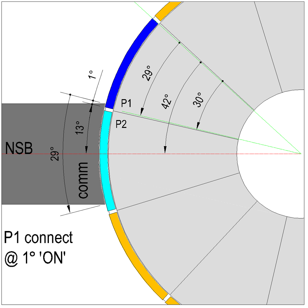
                      • [IMG][/IMG]
                        Image 1 - P1 connecting.

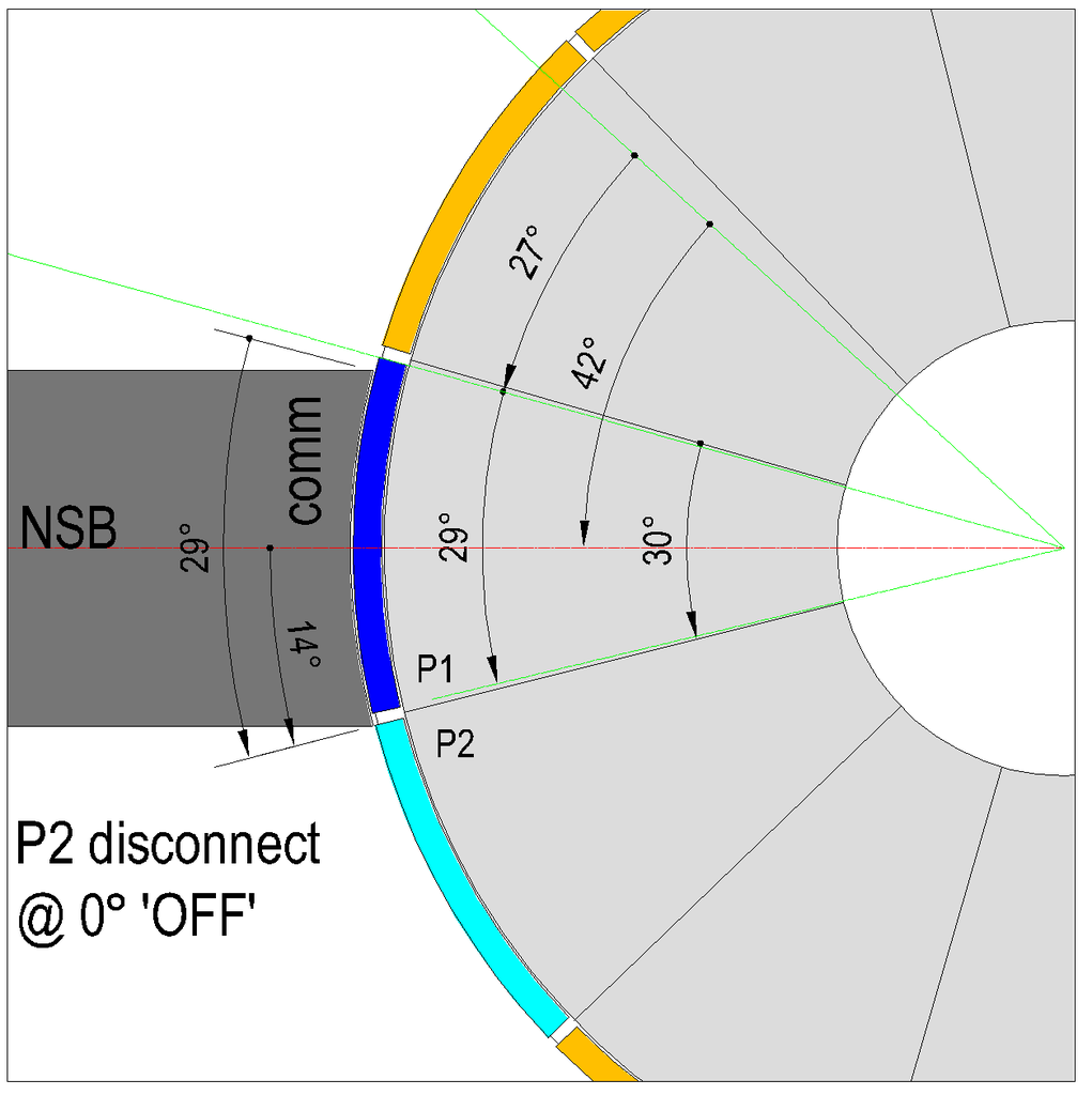
                        [IMG][/IMG]
                        Image 2 - P2 disconnecting.

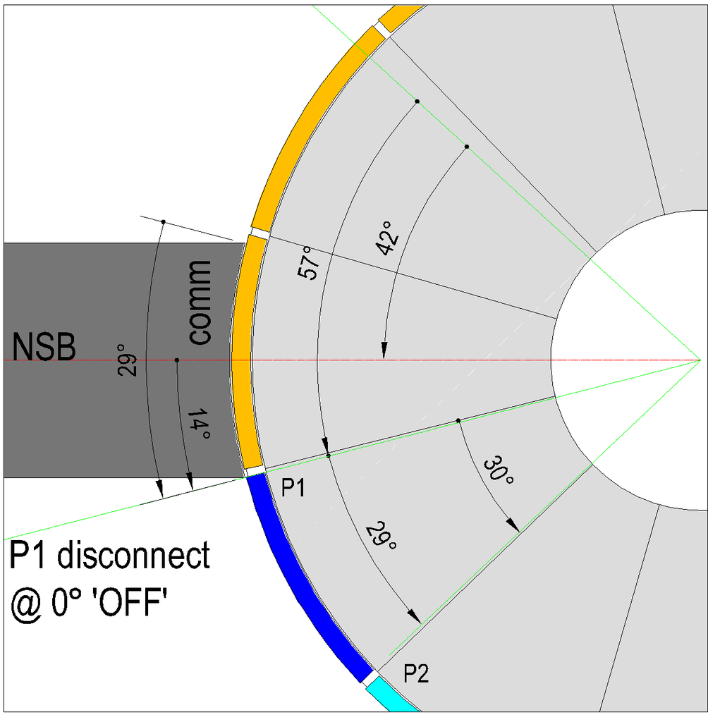
                        [IMG][/IMG]
                        Image 3 - P1 disconnecting.

                        *This post does not involve single or double commutator motors.
                        *This post only considers the relationship of the commutator segment(s) and a single brush to establish the critical sweep angle from connection to disconnection.
                        *These images are for a 12 pole rotor 30° per pole.
                        *The angles are whole numbers only.
                        *The brush is equally divided by the North Stator Bisector.
                        *The brush is the same width as the comm segment, 29°.
                        *The images indicate a 1° angle of separation between the comm segments.
                        *The 'ON' and 'OFF' angles are assumed to be 'ideal' at 5° and 20° respectively.

                        An explanation of the figures :

                        Image 1.
                        P1 leading edge has connected by 1°. P1 trailing edge is 29° behind the leading edge and is 42° above the NSB.

                        Image 2.
                        P2 trailing edge has disconnected by 0°. The image has advanced by 27° from Image 1.

                        Image 3.
                        P1 trailing edge has disconnected by 0°. The image has advanced by 57° from Image 1.

                        The critical angles :

                        Depending on the winding of the chosen design, single, pairs or groups the angle between the first and last coil bisector must be added to the sweep angle plus the 'ON' and 'OFF' angles.

                        Example 1 - P1 analysis. A 4 pole pairs winding on this rotor has 120° between the Coil 1 and Coil 2 bisectors. P1 Coil 1 bisector is set to be 'ON' at 5° past the NSB and accordingly P1 Coil 2 bisector is 'ON' at 125°. For P1 to disconnect it must advance 57°placing the 'OFF' angle for P1 Coil 1 bisector at 62° past the NSB and accordingly P1 Coil 2 bisector is 'OFF' at 182° past the NSB. This is 22° past the 'ideal OFF' angle and 2° past South Stator Bisector (SSB) before disconnection. It is concluded a 4 pole pairs wind is not viable for a 12 pole rotor.

                        Example 2 - P2 analysis. The same 4 pole pairs winding. P1 Coil 1 bisector is set to be 'ON' at 5° past the NSB. Accordingly P2 Coil 2 bisector is 'ON' at 155° past the NSB. For P2 to disconnect it must advance 27° placing the 'OFF' angle for P2 Coil 2 bisector at 182° past the NSB. Both methods achieve the same result and the conclusion is inevitably the same.

                        Example 3 - P1 analysis. A 5 pole single coil winding. The coil bisector 'ON' angle is 5°. The bisector has to sweep 57° before disconnection giving an 'OFF' angle of 62°. Adding an 'ideal OFF' angle of 20°, 82°, leaving 98° for timing adjustments.

                        Happy Hunting

                        mark

                        Comment


                        • Originally posted by sampojo View Post
                          If a brush here would be 36º wide, it would be twice as wide as a comm segment.
                          The working assumption is your 10 pole motor has 10 comm segments at 36º each, not 20 @ 18º each.

                          Originally posted by sampojo View Post
                          If it helps to find out if this design has any inherent good qualities, my brushes are about 3/4's the width of the comm segments.
                          Thank you Sam. As UFO has already remarked, that makes your brush approximately 27º wide.

                          That means your connected comm has to sweep approximately 36 + 27 = 63º from connection to disconnection. Working with a combined 'ideal ON / OFF' angle of 25º, gives you 88º. Thats leaves 2º for timing adjustments.

                          UFO has added a useful image of the importance for alignment of the double comm rotors, so accuracy is paramount when there is only 2º to play with.

                          Happy Hunting

                          mark

                          Comment


                          • Originally posted by Ufopolitics View Post
                            Then join the arguments Mr. Hunting Ross...
                            Just for clarity. I have no argument with Sam or his motor.

                            My involvement on this specific topic is to tidy up unfinished business relating to incorrect comments relating to 4 pole pairs pertaining to one of my historic CAD schematics.

                            There has been to date, a robust discussion on the subject. And I'm certainly not 'falling out' with anyone over the subject.

                            In fact. With my last post on this subject, if this doesn't settle the matter there is no reason to go any further with it. It can not be put any simpler.

                            Happy Hunting

                            mark

                            Comment


                            • Time and Space...

                              Mark,

                              Just looking at P1 segment with brush making contact from on to off position is enough to see how this works...We do not need P2 for below explanation...

                              The operation is simple, we just need to look at your nice close up CAD from FIG 1...let's play it in slow motion.

                              P1 is turning On, Coils are energized, then the magnetic interaction starts moving the shaft until it disconnects commutator segment from brush.

                              1-Now, can you realize this is a single operation?

                              2-Can you realize they take place within the same, exact Time?

                              3-Can you realize the sweeping angles from both, commutator segment and Coils wound at Armature spins together, since they are attached at the same rotating Shaft?

                              Then why in this World do we need to add brush-segment sweeping angle plus coils bisector sweeping angle like if they occur at different Times/Angles?...Or delayed by any 'unknown' reason?...

                              Even after all my previous posts...and diagrams...you have not been able to see that this is a single timed operation?

                              They both take exactly the same Time and Rotation Space from the complete 360º spin.

                              Again, the positioning of the whole switch, could be anywhere, but, as long as it is attached to the same shaft...where all coils are attached...We are talking the same exact Consumed Time for both Operations.


                              What I see is that... until you do not see this...We can not keep discussing about further alignments in your motor.


                              Thank you Sam. As UFO has already remarked, that makes your brush approximately 27º wide.

                              That means your connected comm has to sweep approximately 36 + 27 = 63º from connection to disconnection. Working with a combined 'ideal ON / OFF' angle of 25º, gives you 88º. Thats leaves 2º for timing adjustments.
                              Above you wrote "connected commutator"...but, connected comm. what?...segment?...or whole comm.?...think you missed the word right?


                              Related to Sampojo...please, do not tell him to add both angles Mark...he is enough confused here, because of previous attacks from this delusional guy...Let allow him to answer my previous post addressed to him first, to see if he understood everything I wrote....and if so...I rather wait to see His results after he test his ten pole motor.


                              Sincerely


                              Ufopolitics
                              Last edited by Ufopolitics; 05-16-2015, 09:18 PM.
                              Principles for the Development of a Complete Mind: Study the science of art. Study the art of science. Develop your senses- especially learn how to see. Realize that everything connects to everything else.― Leonardo da Vinci

                              Comment


                              • Originally posted by Ufopolitics View Post
                                P1 is turning On, Coils are energized, then the magnetic interaction starts moving the shaft until it disconnects commutator segment from brush.
                                I truly do understand the mechanics of this operation. It pains me that with all that has been written and drawn on this topic we can not come to understand each other.

                                Your comment above is agreeing with me, yet you think I still don't understand.

                                The coils are energised. The shaft with the commutator and the coils, all together, move from connection to disconnection. I understand that. The quantity of that movement is described by the width of the commutator segment plus the width of the brush. They all move together that distance together. And those coil bisectors (pairs and groups) move that distance because they all move together.

                                Originally posted by Ufopolitics View Post
                                Then why in this World do we need to add brush sweeping angle plus coils sweeping angles like if they occur at different Times/Angles?...Or delayed by any 'unknown' reason?...
                                Because. In one of your schematics, which seems a very long time ago now, you showed P1 just connecting with P2 still fully connected and concluded the timing was good. When in fact P2 still had to move (with everything else together) to disconnect which moved the P2 bisector past the ideal OFF angle.

                                If I made a 120º cardboard cut out representing the angle between the two coil bisectors of a 12 pole 4 pole pairs wind and glued that to a shaft and made that shaft rotate 57º representing the connection to disconnection of the brush with the comm segment. I wouldn't be surprised that I could fit a 13º piece of cardboard in what was left of the semi circle that would ultimately limit the rotation of this shaft. I would be surprised when it didn't all fit together if that 13º piece of cardboard was supposed to be 25º.

                                Originally posted by Ufopolitics View Post
                                What I see is that... until you do not see this...We can not keep discussing about further alignments in your motor.
                                I agree that there is no more mileage in discussing this point. It seems neither of us are convinced by the others persuasion.

                                Originally posted by Ufopolitics View Post
                                Above you wrote "connected commutator"...but, connected comm. what?...segment?...or whole comm.?...think you missed the word right?
                                Correct. It wasn't as clear as it could be. In the context it seemed OK. Being I was talking about the connection to disconnection. If that confused anyone, apologies for that.

                                Keep Hunting

                                mark

                                Comment

                                Working...
                                X