 Tweet
Tweet
Imperial P56 All N Asymmetric Winding Possibilities_1
Hello to All,
Previously I have shown a possibility of overlapping the Pairs in the All North Imperial shown below:
[IMG]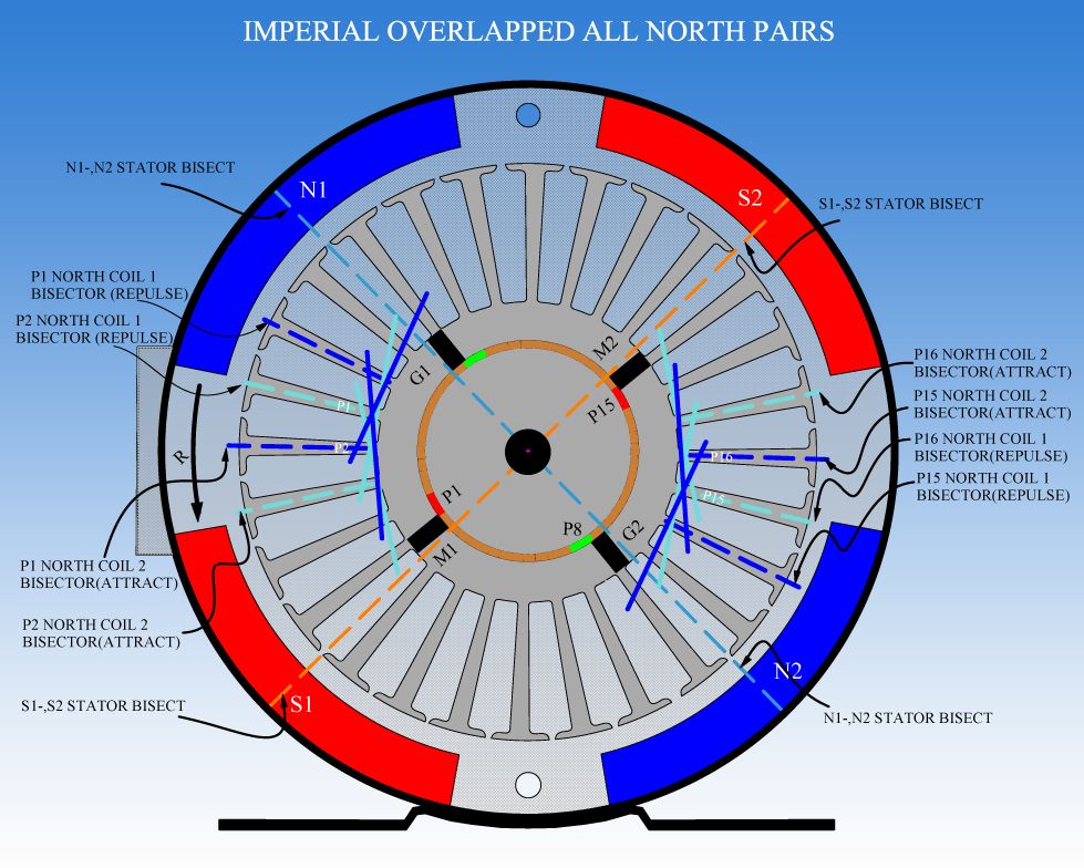 [/IMG]
This 'Overlapping' of the All North Pairs were seen working fine before in the AN1 Model smaller Radio Shack Five Poles, done by Garry Childers, by doing this we are bringing to a more compact formation of All Four Coils Bisectors taking place when we are firing Two Pairs.
[IMG]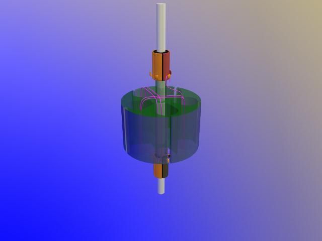 [/IMG]
We see above a frame from the video of the Five Pole 3D Model, it is noticed that each Coil in the Pair is sharing One(1) Common Pole, meaning, overlapping by one pole. That was the AN1 Configuration.
However, when applying this concept from a five pole rotor and two stators to a 28 pole rotor and four stators...we have much more possibilities to play with searching for better Gaps to time machine, looking for that 'Sweet Spot' reducing Amps draw, without sacrificing Top Performances from RPM's and Torque.
In above Diagram of Imperial, each Coil in the Pair is wrapped around Five Poles, as there are Three (3) common poles 'Shared' between both coils in the Pair, and we understand this is "modifiable", by interlacing/overlapping coils either closer together or further apart, in order to expand or contract all four bisectors, by having either more common coils or less common coils.
So, We can have up to Four (4) Common Poles in the Pair (very compact Bisectors, Widest margin to set timing) or up to just One (1) Common Pole (Max Expanded Arrangement of Bisectors, Narrowest Margin to set Timing).
However, We must understand that by narrowing Bisectors (more shared or common poles) We are reducing the Throw Out Angles which would cause a reduction in overall speed or RPM's...and a Gain in Torque...BUT, again, We have quite some probabilities to test there.
This is it, for the All North Imperial Overlapped Coils in the Pair ...However, I will show in a continued post, another way to wind the All North, not overlapped, which is simpler to do...You guys decide which way to test first.
Regards to All
Ufopolitics
Hello to All,
Previously I have shown a possibility of overlapping the Pairs in the All North Imperial shown below:
[IMG]
 [/IMG]
This 'Overlapping' of the All North Pairs were seen working fine before in the AN1 Model smaller Radio Shack Five Poles, done by Garry Childers, by doing this we are bringing to a more compact formation of All Four Coils Bisectors taking place when we are firing Two Pairs.
[IMG]
 [/IMG]
We see above a frame from the video of the Five Pole 3D Model, it is noticed that each Coil in the Pair is sharing One(1) Common Pole, meaning, overlapping by one pole. That was the AN1 Configuration.
However, when applying this concept from a five pole rotor and two stators to a 28 pole rotor and four stators...we have much more possibilities to play with searching for better Gaps to time machine, looking for that 'Sweet Spot' reducing Amps draw, without sacrificing Top Performances from RPM's and Torque.
In above Diagram of Imperial, each Coil in the Pair is wrapped around Five Poles, as there are Three (3) common poles 'Shared' between both coils in the Pair, and we understand this is "modifiable", by interlacing/overlapping coils either closer together or further apart, in order to expand or contract all four bisectors, by having either more common coils or less common coils.
So, We can have up to Four (4) Common Poles in the Pair (very compact Bisectors, Widest margin to set timing) or up to just One (1) Common Pole (Max Expanded Arrangement of Bisectors, Narrowest Margin to set Timing).
However, We must understand that by narrowing Bisectors (more shared or common poles) We are reducing the Throw Out Angles which would cause a reduction in overall speed or RPM's...and a Gain in Torque...BUT, again, We have quite some probabilities to test there.
This is it, for the All North Imperial Overlapped Coils in the Pair ...However, I will show in a continued post, another way to wind the All North, not overlapped, which is simpler to do...You guys decide which way to test first.
Regards to All
Ufopolitics


") Back at it by the weekend...
Back at it by the weekend...


Comment