Announcement

Collapse
No announcement yet.

My Asymmetric Electrodynamic Machines

Collapse
X
 
  • Filter
  • Time
  • Show
Clear All
new posts

  • Originally posted by sampojo View Post
    Ufo's original comparison P214 post#6420

    Windings used:


    The first is the original Radioshack winding, and the second is Ufo's 5-pole unipolar I doctored a little, that I think Gary used too.

    Not sure which was which on Gary's, If I come up with something based on his descriptions I will post.

    AN-3 was a 5-pole wound like a 3-pole, singular poles per coil, like Midaz's A-1MoGen approach, correct? no diagram. To get generator and motor brush placements I should look at a 3-pole diagram?


    AN-2 ??


    Trying to analyze the winding design of AN-1 and see about applying it across other armatures... gotta see these side by side...
    Sampojo

    My design is the Singular Coil that is the same size as the magnet or a little bigger than the magnet... (NOT a one pole coil, like AN3)...
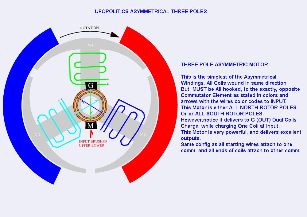
    One pole coil is only for the 3pole motor/no choice .

    AN2, my design, the coil was the same size as the magnet. The singular coils covered two poles per coil.

    Keep it Clean and Green
    Midaz

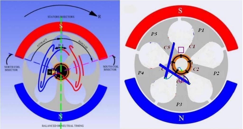
    From the original image below, the singular coils are the same size as the magnet On repulsion mode... Highest TORQUE with high RPMs
    Attached Files
    Last edited by Midaztouch; 04-27-2015, 10:53 PM.

    Comment


    • SpreadSheets

      @All

      Here the spread sheets with the results calculated

      The Goldmine Benchmark


      The North South Radio Shack Winding


      The All North Version 1


      The All North Version 2


      The All North Version 3


      A simple note on the averaging method High RPM reading + Low RPM reading /2 = average RPM reading

      (High Amps in + low Amps in) /2 = average amps in

      Battery was always kept above 12.1 volts during each test while motor was running.

      I will try to answer your questions but I think the spread sheet is self explanatory. Read my post above for better understanding of the way the test was conducted.

      Cheers

      Garry
      Last edited by GChilders; 04-27-2015, 10:02 PM.

      Comment


      • A Chart...Great!

        Originally posted by GChilders View Post
        @All
        I have finished pulling all of the information on the video off and putting it into spread sheets. First let's go over the timing settings on the video and how the test's were done. First I set the motor being tested to position one. On the video I showed this as being the thick line in the center of the other four lines. This timing setting is the same setting as the symmetrical motor uses. Remember I marked the brush retainer long protrusion on the brush ring so that I could return the brush ring to it's original location after grinding the protrusion off. This is the oem's timing position that they feel gives the best performance for their motor, and as it happens it is also the best timing position for a couple of the other windings also.

        Next I ran the following tests in a Clockwise motor rotation. All in this timing location. 30 seconds for the Motor Brush Pair, switched it off, and then switched on the generator brush pair and ran it by itself for 30 seconds. Finally while the generator brush pair was running I switched on the motor brush pair and ran the two pairs together for 30 seconds. As I went to the video rather than having all of the test I cut the center 10 seconds out of each run. That is the order all of the video's are presented in. MBPSetting 1, GBP Setting 1, BBP Setting 1. I then reversed the wiring and ran the same three tests in reverse. I did not include the CCW tests because I thought it would lead to more confusion.
        Now after I videoed these tests I changed to timing Position 2 on the motor. In this location the brushes are rotated towards in the clockwise direction I have called it 5 degrees although it is actually closer to 7 degrees. It is the width of the long slot on the motor that locks in the brush ring. This rotates the brushes to a point to favor attraction. This would in auto lingo give a retarded timing setting of 5-7 degrees, not from the center of the stators, because I have not calculated that measurement, It is simply retarded 5-7 degrees from the oem timing location. After conducting the six tests that were conducted in setting one. The timing was set to position 3. This location retards the timing an additional 5 to 7 degrees towards the attraction side of the stators.
        So keep this in mind : Position 1) is what the oem considers the perfect timing for their motor, Position 2)and 3) FAVORS THE ATTRACTION MODE by rotating the brush retainer clockwise, by moving the brushes in that direction the rotor will receive the electrical charge that generates the magnetic field later in the rotation of the rotor. Being closer to the southern pole of the motor it should enhance the attraction of the electromagnet to the south pole. 3) moves it another 5 to 7 degrees in that direction favoring the attraction mode even more.

        In the next two positions the brush retainer is returned to it's original position and then rotated in a counter clockwise rotation THIS FAVORS THE REPULSION MODE by turning the brushes into the direction of the rotation we are advancing the timing of the electrical charge so that the magnetic force comes earlier in the rotation of the rotor.
        4) is advanced 5 to 7 degrees towards the North Pole stator. This creates stronger repulsion in the interplay between the two opposing magnetic forces. Just as UFO has said all along. 5) is advanced another 5 to 7 degrees towards the North Pole to give possibly a stronger interplay in the repulsion of the rotor. This does not always happen in either direction because the sweet spot seems to give the very best combined totals with the very least drain of resources. Moving in either direction from the sweet spot performance suffers.
        And our limited supply, Battery Charge suffers in a big way.

        Cheers

        Garry

        Great Garry!,


        So, I think We all could resume your time settings...

        You used the Neutral Timing (same as OEM Symmetric)...as Timing #1

        From there, favoring Attract Mode you did the other two timings T#2 & T#3, by a difference of like 5º - 7º diff between Timings

        Then T#4 & T#5 were done towards Repulse Mode, moving firing towards North Stator also about 5º - 7º between each Timing

        So, more or less where was your "sweetest" spot located between...?

        And please, let me propose a couple of things and see if You All agree with me:

        To take out of this testing the AN3...It is a Motor We have never done here in the 5 poles...and each pole circumference is way too small compared to Stator Magnet size...so, it could never get even close to the AN1 or AN2 performance.

        And also the North South Winding...since a while back I did this video, where I compared both Machines...as I explained this All North were far superior...

        So,please, I believe We should do this in order to save time, work and less confusing readings.

        About Timing into the "Attract Zone" of All Norths...

        I will repeat this again...even though I touched this issue before and for a long while...but I consider it is CRITICAL for Attract Mode Timing.


        Whenever We time towards Attract Mode...We MUST ALWAYS REMEMBER TO CONSIDER TWO Pairs (AN1), or even TWO Single Coils(AN2) by their TWO respective Commutator Elements making contact with both Motor Brushes, then we must look at the Coil or Pair that is leaving the contact according to rotation, following its 'last' points of contacts until is completely OFF,...making sure NONE of its Bisectors passes the South Stator Bisector while is still ON.

        As this will KILL performance completely.


        Regards


        Ufopolitics
        Principles for the Development of a Complete Mind: Study the science of art. Study the art of science. Develop your senses- especially learn how to see. Realize that everything connects to everything else.― Leonardo da Vinci

        Comment


        • Excellent Chart!

          Originally posted by GChilders View Post
          @All

          Here the spread sheets with the results calculated

          The Goldmine Benchmark


          The North South Radio Shack Winding


          The All North Version 1


          The All North Version 2


          The All North Version 3


          A simple note on the averaging method High RPM reading + Low RPM reading /2 = average RPM reading

          (High Amps in + low Amps in) /2 = average amps in

          Battery was always kept above 12.1 volts during each test while motor was running.

          I will try to answer your questions but I think the spread sheet is self explanatory. Read my post above for better understanding of the way the test was conducted.

          Cheers

          Garry
          Garry,

          My Friend, according to my experience with Asymmetric Machines, basically in the R/S Motor... I believe I am 'qualified' to say You have done an Excellent Job...when looking at the Old R/S Five Poles North-South Wind, and being able to get those 0.5~0.6 amp draw readings!!

          I know that is no 'piece of cake' to achieve!...got to be done with LOTS of patience ...

          It is "self explanatory", plus you have high lighted the sweetest spots in green line readings...

          So, yes, all this results were expected...at least by me, is what I'm saying...

          The AN1 and AN2 Amp draw is impressively low!!

          Resuming for what I can see the sweetest spots are found in T#1 and T#2, meaning in Attract Mode, right?...(And I am referring basically to AN1 & AN2, since I am not even looking at N/S nor AN3)


          Thanks, excellent job Garry!!


          Regards


          Ufopolitics
          Last edited by Ufopolitics; 04-27-2015, 10:31 PM.
          Principles for the Development of a Complete Mind: Study the science of art. Study the art of science. Develop your senses- especially learn how to see. Realize that everything connects to everything else.― Leonardo da Vinci

          Comment


          • Originally posted by Midaztouch View Post
            Originally Posted by Midaz
            Lowest setting = 1.9volts @ 21amps... 40watts starts RPMs
            Highest setting = 20volts @ 21amps
            Quote:
            Originally Posted by HuntingRoss View Post
            I make that 39.9W and 420W respectively.

            420W seems high for a no load test ?

            Hunting
            The DC Power Supply was set on 21 Apms. It was the baseline for amps.
            I note you have corrected the 60W to 40W, which is fair enough...but I don't understand what you're saying about the 21 amps...

            What was the power at 20v ?

            Presumably it was 420W no load.

            Hunting

            Comment


            • Originally posted by HuntingRoss View Post
              I note you have corrected the 60W to 40W, which is fair enough...but I don't understand what you're saying about the 21 amps...

              What was the power at 20v ?

              Presumably it was 420W no load.

              Hunting
              Before the testing started, the engineers set the machine on 20 Apms... From their test results of thier New EV Switch Reluctant/SR motor, 20amps was the baseline for thier motor.

              It seems like they wanted used 20amps for a comparison of their SR motor in RPMs... They didn't want to do the test RPMs test, torque test was out of the question! The CEO of Sales made the staff do the RPMs run. The head engineer didn't bother to leave his desk when the CEO asked him to start the power supply run... Or look at me, when I walked past him and said "Thank you" went starting and leaving.

              Keep it Clean and Green
              Midaz
              Last edited by Midaztouch; 04-28-2015, 04:19 AM.

              Comment


              • The vid finally up on YT. Take a look and tell me what you think.

                1.9volts @ 21amps... 40 watts starts RPMs. Start of vid
                20Volts @ 21apms... 420 watts vid's peak RPMs at the end(did you hear those RPMs increasing to 20 volts)

                Remember, this motor is handmade. It's not balanced and it has a lot of Mechanical drag loses.

                If you listen carefully, you can hear a wire scraping under the magnets under low RPMs. It got stuck under the magnets durng transporting.

                [VIDEO]https://m.youtube.com/watch?v=xwcPckoSbtA[/VIDEO]


                Keep it Clean and Green
                Midaz

                This place is huge. We were in a tiny back office. The front main testing lab is all white with ALL state-of-the-art equipment $$$$$$$$. This is an old picture, it bigger! It covers Almost all of the land.
                Attached Files
                Last edited by Midaztouch; 04-28-2015, 02:42 AM.

                Comment


                • Originally posted by Midaztouch View Post
                  The vid finally up on YT. Take a look and tell me what you think.

                  1.9volts @ 21amps... 40 watts starts RPMs. Start of vid
                  20Volts @ 21apms... 420 watts vid's peak RPMs at the end(did you hear those RPMs increasing to 20 volts)

                  Remember, this motor is handmade. It's not balanced and it has a lot of Mechanical drag loses.

                  If you listen carefully, you can hear a wire scraping under the magnets under low RPMs. It got stuck under the magnets doing transporting.


                  Keep it Clean and Green
                  Midaz

                  This place is huge. We were in a tiny back office. The front main testing lab is all white with ALL state-of-the-art equipment $$$$$$$$. This is an old picture, it bigger! It covers Almost all of the land.
                  Did you take any temperature measurements of the motors case before and after you did the 420 W run? I'm curious as to the amount of heat generated within the windings with so much current.

                  Comment


                  • Originally posted by dyetalon View Post
                    Did you take any temperature measurements of the motors case before and after you did the 420 W run? I'm curious as to the amount of heat generated within the windings with so much current.
                    It was room temp before and after. I had to carry it on my shoulder with my face on the case around that huge building trying to keep up.

                    Is 20 amps a lot of current for 18awg wire?
                    From my calculations the motor should be able to handle 32 amps with no problems
                    Last edited by Midaztouch; 04-28-2015, 04:16 AM.

                    Comment


                    • Originally posted by Ufopolitics View Post
                      Hello Sam,

                      Hey Bistander, thanks for posting that forklift armature!

                      ...
                      ...

                      I tell you it is NOW a piece of cake to get an Imperial Kit and just put it together and wind it...

                      ...
                      ...
                      Regards

                      Ufopolitics
                      Hi UFO,
                      Thanks a ton for all you've done. Imperial Kit info please? Almost bought one when i read this. If you posted the Kit-path Rx before in this massive thread, please link it Kind Sir.

                      Besides EV Everything-ExpensiveDOTcom's 24VDC 750W Bosch alternative, any other 24VDC Candidate replacements discovered without going to 36VDC?

                      Is there an Asymmetrical application for Cole-Bedini Window Motor's 90 degree Generator Coil? This 3rd question does not fit this thread, so please PM me if you can point me to succeed with the Lockridge 90 degree coil configuration. Coil shorting and/or un-shorting will be my next focus.

                      Thank you All for posting about Fiber-Fix for binding small motor bodies together.

                      -Ward
                      JC4me

                      Comment


                      • Originally posted by HuntingRoss View Post
                        I note you have corrected the 60W to 40W, which is fair enough...but I don't understand what you're saying about the 21 amps...

                        What was the power at 20v ?

                        Presumably it was 420W no load.

                        Hunting
                        Mark,

                        The 21 Amps means 'Max Current Limit Settings' which is set up at PSU, which means they were regulating Voltage while Amps was fixed to Max Output.

                        It could be done the other way around, which is the proper way I think, meaning to set Amps Output 'Floating' (not fixed) so, depending on Voltage increase the PSU will do 'the math' automatically according to amps demand from machine.

                        It seems too many amps applied for such low voltage at start up, eg:1.9V X 20A...but Machine does take it well...

                        The advantage of an Asymmetric Machine is that since they are Open Circuits, closing up only for nano seconds when each coil is fired, there is NO time enough for Amps to fully develop within energized circuit, since Amps in order to 'populate' in an ascending and steady curve require a full time closed circuit. Actually the proper reading needs to be done with a DC Pulsed Amp Meter, (have no idea if that kind of tool has been designed yet...) that would calculate 'an average' operating amps per fraction of time.


                        Cheers


                        Ufopolitics
                        Principles for the Development of a Complete Mind: Study the science of art. Study the art of science. Develop your senses- especially learn how to see. Realize that everything connects to everything else.― Leonardo da Vinci

                        Comment


                        • UFO Imperial Kit

                          Originally posted by JC4me View Post
                          Hi UFO,
                          Thanks a ton for all you've done. Imperial Kit info please? Almost bought one when i read this. If you posted the Kit-path Rx before in this massive thread, please link it Kind Sir.

                          Besides EV Everything-ExpensiveDOTcom's 24VDC 750W Bosch alternative, any other 24VDC Candidate replacements discovered without going to 36VDC?

                          Is there an Asymmetrical application for Cole-Bedini Window Motor's 90 degree Generator Coil? This 3rd question does not fit this thread, so please PM me if you can point me to succeed with the Lockridge 90 degree coil configuration. Coil shorting and/or un-shorting will be my next focus.

                          Thank you All for posting about Fiber-Fix for binding small motor bodies together.

                          -Ward


                          Thanks Ward,

                          Below is the only "UFO KIT" available...that I could find...

                          [IMG][/IMG]


                          Just kidding...


                          The Info is at page 97 and you could see direct link post below:

                          LINK TO UFO KIT

                          Now, the "already wound" Rotor is NOT Asymmetrical...so, make sure rotor is NOT wound, however, Dyann knows exactly what this is all about.

                          Thanks for your interest in Asymmetrical Machines


                          Regards


                          Ufopolitics
                          Principles for the Development of a Complete Mind: Study the science of art. Study the art of science. Develop your senses- especially learn how to see. Realize that everything connects to everything else.― Leonardo da Vinci

                          Comment


                          • Originally posted by Midaztouch View Post
                            It was room temp before and after. I had to carry it on my shoulder with my face on the case around that huge building trying to keep up.

                            Is 20 amps a lot of current for 18awg wire?
                            From my calculations the motor should be able to handle 32 amps with no problems

                            No, 18ga is fine for what you're doing. A lack of heat means your motor is not loosing energy from your rotor windings, but I wonder what losses are incurred by the brushes? I assume you ran it for at least 5 minutes.

                            420 W is a little over 1/2 horsepower. Too bad you didn't have access to a dyno while you were there to measure shaft horsepower. You could compare its output power to input power and calculate efficiency.

                            I think you did a great job building a homemade motor.

                            Comment


                            • Originally posted by dyetalon View Post
                              No, 18ga is fine for what you're doing. A lack of heat means your motor is not loosing energy from your rotor windings, but I wonder what losses are incurred by the brushes? I assume you ran it for at least 5 minutes.

                              420 W is a little over 1/2 horsepower. Too bad you didn't have access to a dyno while you were there to measure shaft horsepower. You could compare its output power to input power and calculate efficiency.

                              I think you did a great job building a homemade motor.

                              Don't forget, there was a strand of 18awg wedged between the rotor and magnets during the check. Plus the bearing is rubbing heavily on the front end plate. The wire was the ping and I stopped the testing. I'm just happy it ran like a normal motor on DC power supply. That was my focus.

                              At 48v, this unbalanced motor is well over 7000rpms with the vibrations to match! The frame is built for 3000rpms with no vibrations.

                              Today, I loaded up my bicycle and peddled 2 hours to the electric motor company. No appointment, no phone call, no email, no nothing.... just showed up! with the A1MoGen, a 12V battery and jumper cables. Told the secretary I needed my motor checked on the DC power supply, then connected the motor up in the main hallway entrance.... Then got a cup of cold green tea and waited.

                              The A1MoGen worked fine on a DC Power Supply.

                              Keep it Clean and Green
                              Midaz "The Negotiator"
                              Last edited by Midaztouch; 04-28-2015, 01:53 PM.

                              Comment


                              • I have a question

                                We have the RPMs and weight of the rotor increasing the torque.


                                Should we even care about Horsepower anymore?!
                                Last edited by Midaztouch; 04-28-2015, 01:44 PM.

                                Comment

                                Working...
                                X