Announcement

Collapse
No announcement yet.

My Asymmetric Electrodynamic Machines

Collapse
X
 
  • Filter
  • Time
  • Show
Clear All
new posts

  • Magnetic fields

    @Raul
    Interesting stuff on the magnetic fields. I recently did a video on an experiment that I did not think belonged in this video that demonstrated how a weak magnetic force could be overwhelmed and completely redirected by the stronger magnetic force. This was a simple test involving a ceramic magnet and a neodymium magnet and a compass. I took two opposition poles and demonstrated that as the stronger magnet was pushed into the weaker magnet it would stick to the weaker magnet and the compass needle would spin in the opposite direction. Then when pulled apart the compass needle would redirect in the opposite direction again. Then I brought the stronger magnet still in opposition and demonstrated that even though the compass needle still pointed in the direction of the weaker pole the needle could be moved by moving the stronger magnet back and forth. This demonstrates that the magnetic forces are constantly being influenced by the stronger forces inside of the motor. When the battery is producing a current through the electromagnet the permanent magnet's field is being reshaped as the rotor spins through it. Once the electromagnet's field collapses the permanent magnet wants to reestablish it's field. This happens instantly. I think this push back is what gives the coil it's induction.

    Looking forward to the next project. Good Success.

    Cheers

    Garry

    Comment


    • Using Magnets to focus light

      @UFO
      I know of another experiment that demonstrated what is happening here. Magnetic fields can be used to focus light and also electrical discharges. There are many interesting properties to electro magnetic fields. Their influence can be used to focus other electromagnetic fields. You are right about each experimenter being intent on presenting his discovery in the best light. Not all of their findings were incorrect. It is like the story I once heard of four blind men trying to describe what an elephant looked like. The first grabbed ahold of the trunk, and said it is like a snake. The second grabbed ahold of his tusks and said it is like the horn of a rhinoceros. The third grabbed a hold of a leg and said it is thick and sturdy like the trunk of a tree, and the fourth grabbed ahold of the tail and said it is skinny and flexible like the switch of a tree. Obviously an elephant is like none of these things. The point here is to try to take the simple explanations with a grain of salt. Things are always more complicated than they seem. We have very little illumination on the subject and new discoveries help us to understand a single part of the subject. Einstein's mistake was to try to force every field into a simple formula, i.e. the unified field theory. We should not repeat that mistake by throwing everything that has been discovered about electricity and follow every pied piper that comes along. Prove the value and then announce the discoveries that have been made. I have my own thoughts about why things happen the way they do in electromagnetic fields. They are based upon study and experiments that can be reproduced over and over again. I know that these descriptions only show a piece of the puzzle, but at least it is a piece. Until someone can give me irrefutable evidence that new information completely discredits the old information, rather than adds to the understanding, I will maintain that understanding.

      Cheers

      Garry

      Comment


      • Not "the Case"...

        Originally posted by GChilders View Post
        @UFO
        Things are always more complicated than they seem. We have very little illumination on the subject and new discoveries help us to understand a single part of the subject.
        Garry, I know it is VERY difficult to "Imagine" a SINGLE Magnetic Spectrum that offers Multiple and Three Dimensional Properties of very clever Geometries, while it is Dynamically Active...Therefore, I also understand is EVEN HARDER to conceive interactions between TWO of them...

        Einstein's mistake was to try to force every field into a simple formula, i.e. the unified field theory. We should not repeat that mistake by throwing everything that has been discovered about electricity and follow every pied piper that comes along. Prove the value and then announce the discoveries that have been made.
        Right...however, We are still lingering with a Formula that "in Theory" has been accepted...but away from that is NOT proven in Reality.

        I have my own thoughts about why things happen the way they do in electromagnetic fields. They are based upon study and experiments that can be reproduced over and over again. I know that these descriptions only show a piece of the puzzle, but at least it is a piece.
        See, the "thing" here is that I am NOT trying to 'add' illustrations for the understanding of something I have NOT proven to Myself to be true and works...NOPE!...sorry, but "it ain't the case" my friend.

        See, I already have a Developed Machine that WORKS BASED ON THIS COMPLETELY OPPOSITE PRINCIPLE, From what we have learned so far... Meaning,...I am working from Reality already BUILT, towards Theory...not like typically is done...meaning the opposite...when someone have "A Theory" then start putting it together into practice until finishing A working Device...nope, not the case here, my friend.

        That is the reason why I "sound" so sure about it...

        Until someone can give me irrefutable evidence that new information completely discredits the old information, rather than adds to the understanding, I will maintain that understanding.

        Cheers

        Garry
        I will do so...in time...and yes it would be "irrefutable"...


        Regards


        Ufopolitics
        Last edited by Ufopolitics; 04-25-2015, 08:12 PM.
        Principles for the Development of a Complete Mind: Study the science of art. Study the art of science. Develop your senses- especially learn how to see. Realize that everything connects to everything else.― Leonardo da Vinci

        Comment


        • Originally posted by GChilders View Post
          @Raul
          Interesting stuff on the magnetic fields. I recently did a video on an experiment that I did not think belonged in this video that demonstrated how a weak magnetic force could be overwhelmed and completely redirected by the stronger magnetic force. This was a simple test involving a ceramic magnet and a neodymium magnet and a compass. I took two opposition poles and demonstrated that as the stronger magnet was pushed into the weaker magnet it would stick to the weaker magnet and the compass needle would spin in the opposite direction. Then when pulled apart the compass needle would redirect in the opposite direction again. Then I brought the stronger magnet still in opposition and demonstrated that even though the compass needle still pointed in the direction of the weaker pole the needle could be moved by moving the stronger magnet back and forth. This demonstrates that the magnetic forces are constantly being influenced by the stronger forces inside of the motor. When the battery is producing a current through the electromagnet the permanent magnet's field is being reshaped as the rotor spins through it. Once the electromagnet's field collapses the permanent magnet wants to reestablish it's field. This happens instantly. I think this push back is what gives the coil it's induction.

          Looking forward to the next project. Good Success.

          Cheers

          Garry
          Garry,


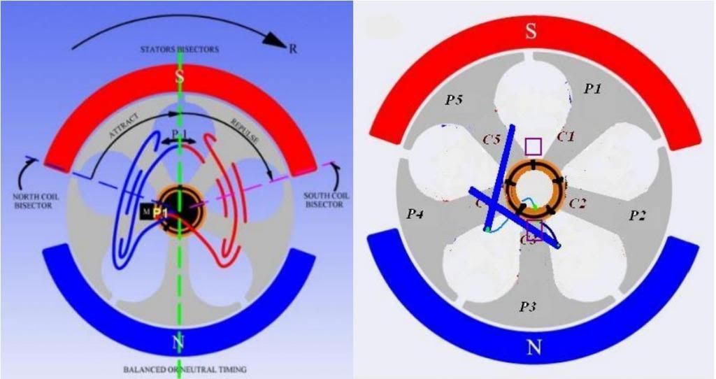
          Now getting back to our Machines...take a look at Imgs below:


          [IMG][/IMG]

          That is exactly what we are doing on All North Asymmetric...at Right Picture...while what Symmetry does in Left Image...

          N1 and N2 represents Two different Timing Settings...like you did on video...agree?

          Now, when timing is deflected to where...CW or CCW according to rotation R...you got closer to the best/sweet spot?

          Understanding "Neutral" would be somewhere at the Symmetrical North Pole Rotor positioning correct?

          Let Us know...

          Regards my Friend


          Ufopolitics


          Ufopolitics
          Last edited by Ufopolitics; 04-25-2015, 08:13 PM.
          Principles for the Development of a Complete Mind: Study the science of art. Study the art of science. Develop your senses- especially learn how to see. Realize that everything connects to everything else.― Leonardo da Vinci

          Comment


          • The flux pattern in that 2 pole stator is completely different from what it will be with the rotor core in place. Removal of the rotor core distroyes the magnetic circuit essentially leaving two separate magnetic circuits, one around each magnet.

            Comment


            • Re: BOTW post 7511:Very good body of work Garry!

              Originally posted by GChilders View Post
              @all

              Well the timing tests have all been concluded documented and finally a video presentation finished. ,,, Let me know what you think guys.


              Cheers

              Garry

              Quite astounding documentation of asym motor performance. Truly, thank you for all your effort.

              Am I wrong, WHY SHOULD WE MESS AROUND WITH ANY WINDING STYLES OTHER THAN THOSE LIKE THE AN-1???

              It is about a factor of 10 times more powerful per amp drawn over the symmetric baseline and about 5 times more powerful than the N-S windings or the other AN-3.

              I would recommend tabulating everything in a spreadsheet. I am a little confused on what exactly you were averaging on some screens though. It seemed like you were averaging motor, generator and both sometimes, or were you averaging all 5 timing settings together? They may not have all been placed in the same location for each series...

              I would recommend also focusing on a selection method of just the best performance position. I suppose this could be dependent on rpm and if a load is present, so for our case just top end would be the starting point. And then each configuration could be compared with just one run. I wouldn't average over the timing positions. Maybe you could just pick out the best runs on your data for each motor and put those in a table.

              Also, do you have the posts or links or drawings handy for each of those windings you have labelled AN-1 to 3?


              Thanks Garry!!!

              Hope my GM quad UP-10 iwas desighed like that AN-1 diagram.

              Ufo: Your youtube version may have been truncated at the 15minute marlk.


              EDIT: I missed the first time thru how closely AN-2 performed with AN-1, duplicating the low amp performance!!! Totally missed the low amp reading on AN-2
              Last edited by sampojo; 04-29-2015, 11:43 PM.
              Up, Up and Away

              Comment


              • Originally posted by sampojo View Post
                Quite astounding documentation of asym motor performance. Truly, thank you for all your effort.

                Am I wrong, WHY SHOULD WE MESS AROUND WITH ANY WINDING STYLES OTHER THAN THOSE LIKE THE AN-1???
                Sampojo

                The problem in the past with the AN-1 was Torque. I believe that in the head to head testing , the OEM was on repulsion and the AN-1 was on repulsion. The OEM won!... HOWEVER, the AN-1 motor may not have been in the Sweet Spot like we know now... The only one who knows, is the person who did the testing, DADHAV. As of now and until he clarifies everything, his testing is inconclusive.

                Because of the above stated testing, I forced my singular coil design (NS-2) into this battle. The singular coil repulsion design was made for torque. I had suspected that the NS-2 would still have high rpm's but a little less than the AN-1 ... I made the A1MoGen to prove my Theory correct.

                Gary's vid was great for finding the timing for the sweet spot of all north motors in attract mode only.
                He had 5 different timing settings. Each timing setting had 3 parts; motor brushes, then generator brushes and lastly both motor and gen together.

                The problem/doubt that still remains is that we don't know how All North Motors(in the Sweet Spot), in attract mode or repulsion mode, compare to the OEM in torque... Torque was in question and it started all the fighting.

                Keep it Clean and Green
                Midaz

                Gary, is the OEM Goldmine motor set on repulse or attraction?
                Last edited by Midaztouch; 04-26-2015, 06:58 AM.

                Comment


                • Negative...

                  Originally posted by bistander View Post
                  The flux pattern in that 2 pole stator is completely different from what it will be with the rotor core in place.
                  Bistander,

                  Completely NEGATIVE!

                  It don't matter whatever FERROMAGNETIC MATERIAL you insert within that Stator, the Stator Magnetic INFLUENCE GEOMETRY will NEVER CHANGE, Just EXPAND, taking over the iron!

                  Removal of the rotor core destroys the magnetic circuit essentially leaving two separate magnetic circuits, one around each magnet.
                  NEGATIVE AGAIN!!

                  Old School from the 1800's...and it seems to be pretty well stamped in your brain.

                  The North and South Poles NEVER, read me well...NEVER "BLEND", "CONNECT", "FUSE" or whatever "adjective" that means North and South have ANY relation between them works here...!

                  There is a WALL between them...that Green Wall, would be there until they disappear completely when making final contact, then BECOME JUST ONE WALL between both Poles.

                  [IMG][/IMG]

                  That Stator there with Magnets GLUED/STOCK to the Housing are in a TEMPORARY "PAUSED AND APPARENT" BALANCE because they are being FIRMLY attached to steel casing...the minute you UN-GLUE them...they will do stick together which is the final VOIDANCE ACTION, after that those two Inner Poles at Attraction die, are gone, good bye!

                  If you insert a ROTOR, or a Steel Cylinder within that Stator...the MAGNETIC INFLUENCE will take over the cylinder drum FERROMAGNETIC MASS like shown on Right Image, and STILL, there would be TWO SEPARATE POLES, You could also add within Stator Hole two pounds of iron loose particles...and still, HALF Particles near the North Pole WILL BE NORTH...as HALF Particles on the South End Pole WILL BE SOUTH, NO MATTER IF THEY ARE "MECHANICALLY BRIDGING" TOGETHER. HOWEVER, when We screen by Viewing Film...there would STILL BE A GREEN LIGHTER WALL DIVIDING BOTH POLARIZED FIELDS, no matter which kind and shape of ferromagnetic mass would be within Stator.

                  ANY MOTOR OUT THERE...Anyone, Symmetric, Asymmetric, Brushless or Brush operated...no matter which one...WORKS BASED ON THE SAME PRINCIPLE:

                  EVERY SINGLE MOTOR OUT THERE, OPERATES BASED ON JUST ONE METHOD,THE PRINCIPLE OF GENERATING A MAGNETIC UNBALANCE WITHIN STATOR WHEN WE PROVIDE ENERGY TO THE ROTOR COILS, IN ORDER TO ACHIEVE ROTATION

                  Removal of the rotor core destroys the magnetic circuit
                  NEGATIVE.

                  The Motor ACTION is the only one that "TRIES" every second of Rotation to UNBALANCE (not "destroy") the Stator Magnetic "Circuit" and NEVER GETS TO ACHIEVE THIS DESTRUCTION ...IF IT EVER DOES...ROTATION IS FINISHED, OVER, GONE...This could happen whenever stator magnets come loose, for example.

                  Hope you understand this facts.


                  Ufopolitics
                  Last edited by Ufopolitics; 04-26-2015, 01:33 PM.
                  Principles for the Development of a Complete Mind: Study the science of art. Study the art of science. Develop your senses- especially learn how to see. Realize that everything connects to everything else.― Leonardo da Vinci

                  Comment


                  • The Real Magnetic Circuit...

                    Originally posted by bistander View Post
                    The flux pattern in that 2 pole stator is completely different from what it will be with the rotor core in place. Removal of the rotor core distroyes the magnetic circuit essentially leaving two separate magnetic circuits, one around each magnet.
                    Bistander,

                    Below is the REAL MAGNETIC "CIRCUIT" taking place within Stator...

                    [IMG][/IMG]

                    On prior Diagrams , both poles for each segment were NOT represented...so the "REAL THING" is laying above...and each Arc Segment Magnet has its OWN Dielectric Wall, which is "OFF CENTER" because it is influenced by the Iron-Steel Housing, which is NOT Displayed here that polarization on outer casing...but it DOES EXIST as well, not to complicate even more this interconnections diagram.

                    ALL THREE Dielectric three dimensional planes DO INTERCONNECT as shown above and below through the intermittent green curves. As they are the ones "IN CHARGE" to bring/fuse together all Field Polarizations into an EQUILIBRIUM.

                    Below Image is of a Two point Five Millimeters (2.5 mm) thickness, Neo Arc Segment (N-35)....screened under Viewing Film...the Dielectric Plane could be seen clearly defined at the EXACT CENTER dividing both polarized fields.

                    [IMG][/IMG]

                    Every single Magnet, screened under Magnetic Viewing Film, will reveal this internal, center located, dielectric wall plane with high accuracy...like an X-RAY to any Magnetic Field.

                    All Magnetic Fields are RULED by this Three Dimensional Dielectric Plane...they are the ones that really "command" each movement the polarized fields make.

                    Therefore, learning FIRST how they "OPERATE"...will lead Us to learn how to "control" or "manipulate" this dielectric plane (not the fields itself, which is what we all have been doing so far...) this knowledge could make any electrodynamic machine design...something "completely out of this world"...

                    [IMG][/IMG]

                    Above is just a FRAME, from an Attraction sequence that was filmed in slow motion...between Two Ceramic Rectangular Magnets coming together under Viewing Film...

                    Dielectric Planes are the "Start" and the "End" Source to both Polarized Fields...Counterspace, where they fly from into space to then return back to that same source...in a constant dynamic state.

                    Taking the "Hint" yet??


                    Regards to all


                    Ufopolitics
                    Last edited by Ufopolitics; 04-26-2015, 01:37 PM.
                    Principles for the Development of a Complete Mind: Study the science of art. Study the art of science. Develop your senses- especially learn how to see. Realize that everything connects to everything else.― Leonardo da Vinci

                    Comment


                    • Originally posted by sampojo View Post
                      Hey bIstander what is the model of that forklift anyway?
                      ......
                      Bistander, did you say the stators were wound electro magnets?
                      Hi Sam,

                      I don't know what forklift. But I think it's an ADC motor. Most of those look about the same on the inside. And yes, it has a 4 pole wound field stator using 4 salient steel poles each having a coil around it. Total resistance of the motor would be on the order of 10 milliohms.

                      bi

                      Comment


                      • Ran my motor on a DC Power Supply today!

                        After a long ride with many big bumps and going over many curbs, a wire came loose and got lodged under the magnets. I heard something scraping when I was running the motor in their lobby but I had to play it cool and didn't want touch/adjust the motor. I just let it spin and smiled.

                        The engineer staff drag me up 2 long fights of stairs and all the way across the warehouse at top speed! I was carrying the 45lbs A1MoGen. They said 5mins that's it... I was a little upset with their treatment but hey, beggars can't be choosy. Anyway, I only needed 3 mins and the A1MoGen got checked on a DC Power Supply.

                        The results from the Vid( will post soon, can't upload to YT for some reason)

                        Lowest setting = 1.9volts @ 21amps... 40watts starts RPMs
                        Highest setting = 20volts @ 21amps

                        I had to stop going up in voltage. I heard a loud "PING" in the motor. I thought about, going up in voltage after the loud ping but I decide to live and fight another day ... The "ping" was the wire lodged under the magnet. When I got home, I pull the wire out and it ran smoothly/no scraping... Instead of using all 28 coils, I will have 27 coils, for now...

                        Conclusion: The A1MoGen was a success on the DC Power Supply.
                        In my opinion, Asymmetrical Motors are VIABLE high-performance electric motors!

                        Keep it Clean and Green
                        Midaz
                        Last edited by Midaztouch; 04-27-2015, 10:21 PM.

                        Comment


                        • Trying to get a handle on windings used in regards to Gchilders tests BOTW p7511

                          Ufo's original comparison P214 post#6420

                          Windings used:


                          The first is the original Radioshack winding, and the second is Ufo's 5-pole unipolar I doctored a little, that I think Gary used too.

                          Not sure which was which on Gary's, If I come up with something based on his descriptions I will post.

                          AN-3 was a 5-pole wound like a 3-pole, singular poles per coil, like Midaz's A-1MoGen approach, correct? no diagram. To get generator and motor brush placements I should look at a 3-pole diagram?


                          AN-2 ??


                          Trying to analyze the winding design of AN-1 and see about applying it across other armatures... gotta see these side by side...
                          Last edited by sampojo; 04-27-2015, 07:46 PM.
                          Up, Up and Away

                          Comment


                          • Originally posted by Midaztouch View Post
                            Lowest setting = 1.9volts @ 21amps... 60watts starts RPMs
                            Highest setting = 20volts @ 21amps
                            I make that 39.9W and 420W respectively.

                            420W seems high for a no load test ?

                            Hunting

                            Comment


                            • Calculations

                              @All
                              I have finished pulling all of the information on the video off and putting it into spread sheets. First let's go over the timing settings on the video and how the test's were done. First I set the motor being tested to position one. On the video I showed this as being the thick line in the center of the other four lines. This timing setting is the same setting as the symmetrical motor uses. Remember I marked the brush retainer long protrusion on the brush ring so that I could return the brush ring to it's original location after grinding the protrusion off. This is the oem's timing position that they feel gives the best performance for their motor, and as it happens it is also the best timing position for a couple of the other windings also.

                              Next I ran the following tests in a Clockwise motor rotation. All in this timing location. 30 seconds for the Motor Brush Pair, switched it off, and then switched on the generator brush pair and ran it by itself for 30 seconds. Finally while the generator brush pair was running I switched on the motor brush pair and ran the two pairs together for 30 seconds. As I went to the video rather than having all of the test I cut the center 10 seconds out of each run. That is the order all of the video's are presented in. MBPSetting 1, GBP Setting 1, BBP Setting 1. I then reversed the wiring and ran the same three tests in reverse. I did not include the CCW tests because I thought it would lead to more confusion.
                              Now after I videoed these tests I changed to timing Position 2 on the motor. In this location the brushes are rotated towards in the clockwise direction I have called it 5 degrees although it is actually closer to 7 degrees. It is the width of the long slot on the motor that locks in the brush ring. This rotates the brushes to a point to favor attraction. This would in auto lingo give a retarded timing setting of 5-7 degrees, not from the center of the stators, because I have not calculated that measurement, It is simply retarded 5-7 degrees from the oem timing location. After conducting the six tests that were conducted in setting one. The timing was set to position 3. This location retards the timing an additional 5 to 7 degrees towards the attraction side of the stators.
                              So keep this in mind : Position 1) is what the oem considers the perfect timing for their motor, Position 2)and 3) FAVORS THE ATTRACTION MODE by rotating the brush retainer clockwise, by moving the brushes in that direction the rotor will receive the electrical charge that generates the magnetic field later in the rotation of the rotor. Being closer to the southern pole of the motor it should enhance the attraction of the electromagnet to the south pole. 3) moves it another 5 to 7 degrees in that direction favoring the attraction mode even more.

                              In the next two positions the brush retainer is returned to it's original position and then rotated in a counter clockwise rotation THIS FAVORS THE REPULSION MODE by turning the brushes into the direction of the rotation we are advancing the timing of the electrical charge so that the magnetic force comes earlier in the rotation of the rotor.
                              4) is advanced 5 to 7 degrees towards the North Pole stator. This creates stronger repulsion in the interplay between the two opposing magnetic forces. Just as UFO has said all along. 5) is advanced another 5 to 7 degrees towards the North Pole to give possibly a stronger interplay in the repulsion of the rotor. This does not always happen in either direction because the sweet spot seems to give the very best combined totals with the very least drain of resources. Moving in either direction from the sweet spot performance suffers.
                              And our limited supply, Battery Charge suffers in a big way.

                              Cheers

                              Garry
                              Last edited by GChilders; 04-27-2015, 08:05 PM.

                              Comment


                              • Originally posted by Midaz
                                Lowest setting = 1.9volts @ 21amps... 40watts starts RPMs
                                Highest setting = 20volts @ 21amps
                                Originally posted by HuntingRoss View Post
                                I make that 39.9W and 420W respectively.

                                420W seems high for a no load test ?

                                Hunting
                                The DC Power Supply was set on 21 Apms. It was the baseline for amps.

                                The company builds IE3 Switch Reluctance motors. SR motors are the foundation of their company. Around the time I went there the first time, they had a prototype EV car motor strapped to the test bench. As you can see, now they have completed two types for production. That's why the head engineer want nothing to do with my motor. His pride is on the line.

                                小ž‹EV”SRƒƒ‚ | *式š社˜Ž’Œ製œ‰€
                                It's in Japanese plus a little English
                                (Check thier company profile on the English side)

                                Keep it Clean and Green
                                Midaz
                                Last edited by Midaztouch; 04-27-2015, 10:16 PM.

                                Comment

                                Working...
                                X