Announcement

Collapse
No announcement yet.

My Asymmetric Electrodynamic Machines

Collapse
X
 
  • Filter
  • Time
  • Show
Clear All
new posts

  • Gary

    No bad! Should be exciting!


    Is the Timing the same as the factory?

    Do to the wind of my design, "Singular Coil", the wind only interacts with one magnet for the 5 rotor pole motor. The timing of the positive input may need some adjustments. As you get closer to TDC, the torque and RPMs will increase. For adjusting the positve input timing, I thought about the RPMs & torque vs power consumption. RPMs & torque vs power consumption equation should be as balanced as possibe to the OEM.

    Do you have a clear pic of the winds for my design? The pic is too blurry for a closeup view.

    Power to the people


    Keep it Clean and Green
    Midaz
    Last edited by Midaztouch; 03-28-2015, 10:49 PM.

    Comment


    • Nice work Garry. I eagerly await the outcome of your tests. I also hope you will include a torque test for all the motors...even a basic setup is very informative for relative performance.

      I have a three more motors to write up, SC#8 #9 and #5.1 and a just finishing off my 120 tooth sprocket to allow rev and torque tests from my motors to a 12" dia dirt bike wheel.

      Happy Hunting.

      mark

      Comment


      • Assembly and burn in period

        @All

        Well the pit crews have been busy with the final adjustments to their motors. All have successfully performed their one hour burn in period with the exception of the AN2 which UFO helped Midaz with. No fault of the design, it was performing very well when a brush came loose about 45 minutes into the test and wreaked havoc with the motor. After quick examination another brush ring was prepared and ready to be installed when it was discovered that the commutator had been severely damaged. The empty brush holder had caught one of the commutator segments and pulled it off of the commutator. Some of the wires for the rotor had also been cut. A new rotor is in progress, I still have 4 gold mine motors left, so it shouldn't take too long to get it back in the competition. In the mean time I will have the AN3 do a burn in and if it passes will move on to starting with the N/S v/s the AN1. Then the AN1 v/s the AN3. By then the new rotor for the AN2 should be ready and the AN2 will be tested. Whew!! Already some surprises have occurred in the burn in periods and I expect more after the timing adjustments have been dialed in. The biggest surprise of all was the performance of the AN1 v/s the stock goldmine. 3500 RPM at 12.4 volts and 750 milliamps for the stock goldmine and over 9100 RPM at 12.4 volts and 1.3 amps for the AN1! Wow is all I can say. This is direct feed only, in the burn in test, just trying to get the optimum setting for the timing. I will video each of the motors as the burn in continues with an eye towards showing how I managed the timing of these motors. It requires quite a bit of extra machining but should really allow me to dial in the timing perfectly. Each of these replications have extra slots cut in the embodiments that allow the brush rings to be spun about 10 degrees in each direction from center and fastened in place. This allows both commutators to be aligned with each other and both brushes to be advanced or retarded together. I am not going to try to split the ring to move the motor brush and generator brush independently of each other. The brush ring has already been weakened by the number of holes drilled and tapped into it. This motor is far too much trouble to strive for that. It would be better to redesign the embodiment with a different brush type such as the ones in drill motors that can be independently mounted. Stay tuned as the battle continues.

        @Midaz
        I have close ups of the AN2. The problem is that I used a clear epoxy in balancing the rotor. Between the green shellac finish and the epoxy it obscured the winds. Since I have to rewind this rotor now, perhaps, it will come out more clear in the photos. Also I shot the photos at a resolution that was really large. When I put in on the website only about 1/3 of the photo showed. I did a quick fix in Paint and resized it. This cost a lot in clarity. I will try to reshoot all of the photos in a more appropriate resolution for the camera. I believe I answered your question about the commutators. All of my replications have always had two commutators per rotor. One commutator does not work!! You will always kill the dipole when the rotor turns 180 degrees and this is where the difference is when comparing the symmetrical motor and asymmetrical. When you force the current to reverse in the coil you cannot capture the collapse of the electromagnetic field. In a later demonstration I will demonstrate the influence of the magnetic and electromagnetic fields. This is what propels these motors, not the magnets. The magnets are much smaller than the field that they project. It is the attraction, repulsion of these fields that can extend well beyond what you might think they are capable of. I have 1" diameter neodymium magnets that I can spin that will spin a similar magnet in the opposite direction 6" away without any difficulty at all. Last, I am aware that the timing on the AN2 is still a work in progress. I explained above that pains that I have gone through to be able to dial in the timing.

        Cheers

        Garry

        Comment


        • Originally posted by GChilders View Post
          The biggest surprise of all was the performance of the AN1 v/s the stock goldmine. 3500 RPM at 12.4 volts and 750 milliamps for the stock goldmine and over 9100 RPM at 12.4 volts and 1.3 amps for the AN1! Wow is all I can say.
          Hi Gary. I'm not certain if that is a good 'wow' or a bad 'wow' but the figures do not surprise me. I have consistently found the asymm motors to draw more current with vastly increased revs. It's the torque I have found to be wanting. I hope your tests highlight where I'm going wrong.

          Originally posted by GChilders View Post
          One commutator does not work!! You will always kill the dipole when the rotor turns 180 degrees and this is where the difference is when comparing the symmetrical motor and asymmetrical. When you force the current to reverse in the coil you cannot capture the collapse of the electromagnetic field.
          Not strictly correct.

          [I've edited this section of my post to correct the inaccuracies.]

          Symm motors and Single Comm Hybrid motors 'flip' the coils as stated...BUT...the point I wanted to make is

          In a symmetric motor the collapsing electromagnetic field is lost as you say, but in a double comm asymm motor and in a single comm twin brush configuration the collapsing field is captured. My SC#6 motor has demonstrated higher output voltage than the PSU input voltage which I can't explain but believe this embodiment to be more efficiently harvesting the collapsing field.

          Happy Hunting

          mark
          Last edited by HuntingRoss; 03-29-2015, 08:56 PM.

          Comment


          • @Garry and Mark...

            Originally Posted by GChilders
            Originally Posted by GChilders View Post
            The biggest surprise of all was the performance of the AN1 v/s the stock goldmine. 3500 RPM at 12.4 volts and 750 milliamps for the stock goldmine and over 9100 RPM at 12.4 volts and 1.3 amps for the AN1! Wow is all I can say.


            Originally posted by HuntingRoss View Post
            Hi Gary. I'm not certain if that is a good 'wow' or a bad 'wow' but the figures do not surprise me. I have consistently found the asymm motors to draw more current with vastly increased revs. It's the torque I have found to be wanting. I hope your tests highlight where I'm going wrong.
            Hello Garry, Hello Mark,

            @Garry: First congratulations Garry on this nice future testing!...Excellent work friend!

            @Mark, I do believe it is a "good" Wow......do some simple math there...the overall amps increase is only 0.55 amps (1.3-0.750), while the RPM's is about TRIPLE the Symmetric Motor.

            Related to Torque, Garry would have to add some EQUAL, IDENTICAL mechanical load to both machines (OEM and whichever of the Asymmetrical ones) then see what happens under mechanical load.

            The worst Symmetrical side is not actually on a Free spin testing (no load) BUT whenever we add mechanical loads.

            I recently bought a couple of tools for my grass cutting...from EGO (Chinese made)...a weed eater and a lawnmower, the later one is absolutely good working machine....but under heavy loads of grass it draws batteries too fast, and batteries are "State of the Art" LiFe with self ventilation and inboard BMS (Batt Management System)...preventing from full drain and compensating each cell for drain as for charging in a balanced state.

            The Weed eater is a nightmare...I have ordered the second one by now...and it has a two stator, 12 pole symmetric, brush motor.

            After a few minutes of running time under load, motor starts to slow down to finally stop...and smoking the freshly dropped resin...meaning, 'steaming hot'

            None of this two tools have a controller but a full trigger switching On or Off.

            I will eventually replace this motor with an Asymmetrical one but have not found a ready to install model (Shaft is pretty big for the size of rotor, and so the attachments to shaft, plus bearings, etc) and factory is not supplying motors by itself up to now. I have Two weed eaters so far, so one would be the OEM...and I will run a short video on this future tests.

            Originally Posted by GChilders View Post
            One commutator does not work!! You will always kill the dipole when the rotor turns 180 degrees and this is where the difference is when comparing the symmetrical motor and asymmetrical. When you force the current to reverse in the coil you cannot capture the collapse of the electromagnetic field.

            Not strictly correct.

            [I've edited this section of my post to correct the inaccuracies.]

            Symm motors and Single Comm Hybrid motors 'flip' the coils as stated...BUT...the point I wanted to make is

            In a symmetric motor the collapsing electromagnetic field is lost as you say, but in a double comm asymm motor and in a single comm twin brush configuration the collapsing field is captured. My SC#6 motor has demonstrated higher output voltage than the PSU input voltage which I can't explain but believe this embodiment to be more efficiently harvesting the collapsing field.

            Happy Hunting

            mark
            Ok, above is a great point from both of you.

            @Mark: You could collect the collapsing field energy by setting the output brushes before reaching the 180º reversal...no doubt about that.
            BUT, you are still reversing each coil as it gets to 180º, therefore when it reaches the second stage to output you will be reversing your output, which means they will cancel any out-coming energy...result: you are collecting energy only from the first step before each coil reverses.

            Related to higher Output than PSU voltage...you will have to measure also the amps to have the complete 'package'.

            However, there is an advantage to have independent coils with one commutator, versus the full symmetrical having an all around fully shorted circuit ...symmetrical systems kind of 'lies' about performance under light loads, BUT, when they are under heavy mechanical loads...under this critical scenario they rapidly kicks to high amp draw way over the stated spec's plus excessive heating till burning up.

            The fully independent coils in dual commutators is in no way comparable to any build that reverses the coils by having one commutator....Coils have a 'brake' here...an 'idling stage' which allows them to cool off plus energy flow in only "One Way". And, like I have written before...the one thing our Asymmetrical Motors would need to perform superb, is to attach a parallel Non Polarized Cap to each independent circuit (coil, pairs or groups)...however, this would have to be calculated related to coil resistance and impedance as to create the perfect tank circuit for each type of winding. Unfortunately we have not gone deep enough into this subject.

            I have done this testing with amazing results...:

            [IMG][/IMG]

            [IMG][/IMG]

            [IMG][/IMG]

            Unfortunately, I don't have the time to work on this right now because of known issues I have posted before.

            Regards to both of you and good luck in your work!


            I am waiting eagerly for those test results Garry!!


            Ufopolitics
            Last edited by Ufopolitics; 03-30-2015, 05:18 PM.
            Principles for the Development of a Complete Mind: Study the science of art. Study the art of science. Develop your senses- especially learn how to see. Realize that everything connects to everything else.― Leonardo da Vinci

            Comment


            • Originally posted by Ufopolitics View Post
              @Mark, I do believe it is a "good" Wow......do some simple math there...the overall amps increase is only 0.55 amps (1.3-0.750), while the RPM's is about TRIPLE the Symmetric Motor.
              Hi UFO. I am probably seeing this from a narrow perspective because I'm trying to apply this technology to powering a scooter (and moving on to a larger EV) but the apparent leverage of Amps & Revs against the OEM has little advantage if the torque is not there. As you know I have been struggling with this. My solution, soon to be realised (or not) with my 120 tooth sprocket is to turn superior revs into torque and then see whether the leverage still exists. I think it will, but I have been wrong before.

              Originally posted by Ufopolitics View Post
              @Mark: You could collect the collapsing field energy by setting the output brushes before reaching the 180º reversal...no doubt about that.
              BUT, you are still reversing each coil as it gets to 180º, therefore when it reaches the second stage to output you will be reversing your output, which means they will cancel any out-coming energy...result: you are collecting energy only from the first step before each coil reverses.
              I maybe have misunderstood this. I thought the the generator brushes took the coil set 'down' removing the field energy and presenting an empty coil set to the motor brushes. In other words...No coil reversal at the motor brush.

              Originally posted by Ufopolitics View Post
              Related to higher Output than PSU voltage...you will have to measure also the amps to have the complete 'package'.
              I've extracted this from my post #7384 in regard to the SC#6

              29th Feb 2015 - Static Scooter Test, Output load tests and photo of build.

              26.5v @ the scooter controller output.
              SC#6 ~ 24.7v @ 2.13A @ 8506rpm @ 26.6v out [52.6W] No load
              Connect SC#5 to SC#6 output
              SC#6 ~ 23.5v @ 3.87A @ 8015rpm @ 26-40v out [90.95W] The output was fluctuating a lot, this doesn't happen with the OEM. A scope of this output would be interesting.
              SC#5 ~ 26-40v @ 2.52A @ 10,878rpm [notional watts 65W]
              Connect OEM 450W to SC#6 output
              SC#6 ~ 23.5v @ 4.09A @ 8054rpm @ 22.2v out [96.1W]
              OEM 450w ~ 22.2v @ 2.62A @ 442rpm [58.16W]

              Once again the SC#6 under load takes less power than the SC#6 no load + SC#5 load. Does anyone have a theory on this ?
              Notice also the OEM 450w pulling 58W compared to SC#5 load @ 31W.

              SC#6 static pull (torque) test 5.9kg (OEM 8.8kg)
              I would need to dig back to find the 24v 450w OEM no load motor results wired straight to the battery but it is very close to the 442rpm loaded off the SC#6 output...which is still buzzing at 8054rpm.

              I still don't know how to interpret these results. The SC#6 loaded is slightly less power than the two motors separately but it's by no means 'free' energy. It's taking 96W to make 58W on the output and takes 52W just sitting there spinning.

              Happy Hunting

              mark

              Comment


              • Future Tests

                @All
                I want to test the following standard tests for small motors. 1)RPM/Voltage This is a very important test and although it is not a true measure of the efficiency of the motor it is a good indicator. 2)RPM/Watts This is a better indicator of the efficiency of the motor but still is not totally accurate. These tests will be conducted with a direct connection to the battery and are a very poor indicator of the abilities of the asymmetric motor as we are not taking advantage of the superior design which allows us to collect and recycle the energy that is in the motor. Also I want to test the temperature; ambient, bushing and case. This will give us an idea of how much energy is being converted into heat within the motor.
                The other tests that I want to include have more to do with the unique abilities of the asymmetrical windings. I consider asymmetrical windings to be those that allow us to collect more from the environment than we are expending in powering the motor. The term commonly used is COP Coefficient Of Performance. A COP of 1 is supposedly the highest value any system is suppose to be able to achieve. The only way that is possible to exceed this is by picking up energy from the environment. Wind exists and has power to move a wind mill, a wind generator, or a sail boat and because little or no energy is introduced on our part the system may have a COP of an infinite value. This is not free energy. It will cost us some money to build a system to collect this energy. I may sound like Captain Obvious at times when I say something like "the energy is already in the environment but only when the wind is blowing". The same can be said for Solar, in the form of Solar Panels, and Gravity, in the form of water mills. These can be considered substantial boosts to energy but only work when the wind, sun, or water are providing the energy to the system. They could be better described as fuel less forms of energy. You do not need gasoline, diesel, alcohol, wood, or coal to power them.
                There is a unique capability of a coil to bring energy into itself from the environment. This is why all coils are called inductors. They have resistance, and they have some capacitance but they have this unique ability to suck up energy as an electromagnetic field is collapsing. Thus electricity is being inducted into the coil, by it's design. All asymmetrical motor designs take advantage of this ability, as do generators and alternators, ignition coils, transformers, LC tank circuits, and LCR tank circuits. Having said all of that these are the tests that I want to perform to make a decision on which of these windings is a true winner. The winner will be decided by it's ability to recharge the batteries that are giving it power. The winding that returns the most charge is the winner, pure and simple. I have built enough of these motors to know that they all out perform the symmetrical motor in torque and RPM/Volt. The question in my mind is, "Which can recharge the batteries the most, so that the life of a battery charge can be extended or deemed completely unnecessary?"
                So here are the tests that I will perform to hopefully get a handle on this before I wind the Imperials.
                1)Lenz test. I will wire a incandescent light in the form of a 12 volt signal lamp to the generator side of the motor, The motor with the least decrease in the RPM of the motor wins. This is the winding that the Lenz effect has the least effect upon the motor. Thus it should create more energy to charge the batteries.
                2)Pulse Width Modulation (PWM) v/s Incremental Increases in Frequency (IIF). This test will be conducted by adding a capacitor and a couple of diodes to the circuit and test to see which method fills the capacitor the quickest throughout the rpm range of the motor. The winding that fills the capacitor with the lowest time elapsed and the method PWM Or IIF will be the winners. I will describe the difference between the two methods when the test is conducted.
                3.The last test I want to conduct is the advantages and disadvantages of a dual system v/s wiring the brushes in series. I cannot see any advantage to the method of wiring the brushes in series, but perhaps I am missing something. When I have wired these gold mine motors in series the motors always take a hit on the rpm. I will also explain this test in more detail later. Usually we increase the voltage by wiring more batteries in series. I have been using independent systems. One for the generator side and one for the motor side. The increase in torque with both methods is significant. I wish to document this effect with this test and compare the results side by side. I know that batteries do not like being charged while they are being drained. The idea here is similar to the Tesla switch, as one system is running the motor the other is collecting energy and then the roles are reversed. At some point the capacitor mentioned in the previous test is filled and when that system begins to be used to power the motor, the capacitor is emptied into the idled system battery. One battery charging and the other drained to run the motor.
                These tests will give me enough confidence to wire the Imperial. They will not be conclusive and will probably not satisfy everyone. If you wish to test other things go right ahead. No one is stopping you from conducting tests, and sharing your results here. I am not here to jump through the hoops that you put in front of me. I have a number of projects waiting for me to complete and the more time that I spend on the gold mine motors, the less I have to spend on the really important ones. I have Imperials waiting to be wound, and quads waiting to be converted to electric power. I will share my findings, take or leave it, I really do not care which you decide to do. There is a saying that I like a lot, "A man convinced against his will is of the same opinion still". I will never be able to convince the doubters that this works. I can only hope that you will give this technology a chance. It may change your mind. I want to get my quads converted. And then move into testing additional findings there. After one of the Quads is converted, I will take it to a dynamometer, and have it thoroughly tested for Horsepower and Torque. I will share my findings then. Torque on these tiny motors is meaningless, They were not designed with torque in mind. The Imperial is a different story. That motor is designed for torque. Massive rotor with a much larger diameter, large diameter wire, to handle massive amounts of voltage and amperage. Large, powerful magnets that will give a huge amount of torque to the motor.
                I am finished with rebuilding the rotor for the AN2 that was damaged during the burn in period. Before I burn it in, I have decided to do a short video on the timing innovations that I have put into these embodiments in order to dial in different effects. By the end of the week I hope to release the first group of tests. I am still working out the details of the first videos in my mind. There are a lot of points that I wish to cover and explore. What constitutes a winner to me once again is a powerful motor that recycles the energy and reenergizes the batteries that are driving it. Energy wasted by conversion to heat is a non-starter for me.

                @Midaz
                Here are a couple of photos of the rebuilt rotor that you asked for.

                Shows the two commutators


                A few different view points with rotor rotated.

                Cheers

                Garry
                Last edited by GChilders; 04-01-2015, 09:53 PM.

                Comment


                • Originally posted by GChilders View Post
                  @All
                  I want to test the following standard tests for small motors. 1)RPM/Voltage This is a very important test and although it is not a true measure of the efficiency of the motor it is a good indicator. 2)RPM/Watts This is a better indicator of the efficiency of the motor but still is not totally accurate. These tests will be conducted with a direct connection to the battery and are a very poor indicator of the abilities of the asymmetric motor as we are not taking advantage of the superior design which allows us to collect and recycle the energy that is in the motor. Also I want to test the temperature; ambient, bushing and case. This will give us an idea of how much energy is being converted into heat within the motor.
                  The other tests that I want to include have more to do with the unique abilities of the asymmetrical windings. I consider asymmetrical windings to be those that allow us to collect more from the environment than we are expending in powering the motor. The term commonly used is COP Coefficient Of Performance. A COP of 1 is supposedly the highest value any system is suppose to be able to achieve. The only way that is possible to exceed this is by picking up energy from the environment. Wind exists and has power to move a wind mill, a wind generator, or a sail boat and because little or no energy is introduced on our part the system may have a COP of an infinite value. This is not free energy. It will cost us some money to build a system to collect this energy. I may sound like Captain Obvious at times when I say something like "the energy is already in the environment but only when the wind is blowing". The same can be said for Solar, in the form of Solar Panels, and Gravity, in the form of water mills. These can be considered substantial boosts to energy but only work when the wind, sun, or water are providing the energy to the system. They could be better described as fuel less forms of energy. You do not need gasoline, diesel, alcohol, wood, or coal to power them.
                  There is a unique capability of a coil to bring energy into itself from the environment. This is why all coils are called inductors. They have resistance, and they have some capacitance but they have this unique ability to suck up energy as an electromagnetic field is collapsing. Thus electricity is being inducted into the coil, by it's design. All asymmetrical motor designs take advantage of this ability, as do generators and alternators, ignition coils, transformers, LC tank circuits, and LCR tank circuits. Having said all of that these are the tests that I want to perform to make a decision on which of these windings is a true winner. The winner will be decided by it's ability to recharge the batteries that are giving it power. The winding that returns the most charge is the winner, pure and simple. I have built enough of these motors to know that they all out perform the symmetrical motor in torque and RPM/Volt. The question in my mind is, "Which can recharge the batteries the most, so that the life of a battery charge can be extended or deemed completely unnecessary?"
                  So here are the tests that I will perform to hopefully get a handle on this before I wind the Imperials.
                  1)Lenz test. I will wire a incandescent light in the form of a 12 volt signal lamp to the generator side of the motor, The motor with the least decrease in the RPM of the motor wins. This is the winding that the Lenz effect has the least effect upon the motor. Thus it should create more energy to charge the batteries.
                  2)Pulse Width Modulation (PWM) v/s Incremental Increases in Frequency (IIF). This test will be conducted by adding a capacitor and a couple of diodes to the circuit and test to see which method fills the capacitor the quickest throughout the rpm range of the motor. The winding that fills the capacitor with the lowest time elapsed and the method PWM Or IIF will be the winners. I will describe the difference between the two methods when the test is conducted.
                  3.The last test I want to conduct is the advantages and disadvantages of a dual system v/s wiring the brushes in series. I cannot see any advantage to the method of wiring the brushes in series, but perhaps I am missing something. When I have wired these gold mine motors in series the motors always take a hit on the rpm. I will also explain this test in more detail later. Usually we increase the voltage by wiring more batteries in series. I have been using independent systems. One for the generator side and one for the motor side. The increase in torque with both methods is significant. I wish to document this effect with this test and compare the results side by side. I know that batteries do not like being charged while they are being drained. The idea here is similar to the Tesla switch, as one system is running the motor the other is collecting energy and then the roles are reversed. At some point the capacitor mentioned in the previous test is filled and when that system begins to be used to power the motor, the capacitor is emptied into the idled system battery. One battery charging and the other drained to run the motor.
                  These tests will give me enough confidence to wire the Imperial. They will not be conclusive and will probably not satisfy everyone. If you wish to test other things go right ahead. No one is stopping you from conducting tests, and sharing your results here. I am not here to jump through the hoops that you put in front of me. I have a number of projects waiting for me to complete and the more time that I spend on the gold mine motors, the less I have to spend on the really important ones. I have Imperials waiting to be wound, and quads waiting to be converted to electric power. I will share my findings, take or leave it, I really do not care which you decide to do. There is a saying that I like a lot, "A man convinced against his will is of the same opinion still". I will never be able to convince the doubters that this works. I can only hope that you will give this technology a chance. It may change your mind. I want to get my quads converted. And then move into testing additional findings there. After one of the Quads is converted, I will take it to a dynamometer, and have it thoroughly tested for Horsepower and Torque. I will share my findings then. Torque on these tiny motors is meaningless, They were not designed with torque in mind. The Imperial is a different story. That motor is designed for torque. Massive rotor with a much larger diameter, large diameter wire, to handle massive amounts of voltage and amperage. Large, powerful magnets that will give a huge amount of torque to the motor.
                  I am finished with rebuilding the rotor for the AN2 that was damaged during the burn in period. Before I burn it in, I have decided to do a short video on the timing innovations that I have put into these embodiments in order to dial in different effects. By the end of the week I hope to release the first group of tests. I am still working out the details of the first videos in my mind. There are a lot of points that I wish to cover and explore. What constitutes a winner to me once again is a powerful motor that recycles the energy and reenergizes the batteries that are driving it. Energy wasted by conversion to heat is a non-starter for me.

                  @Midaz
                  Here are a couple of photos of the rebuilt rotor that you asked for.

                  Shows the two commutators


                  A few different view points with rotor rotated.

                  Cheers

                  Garry
                  Gary

                  I appreciate all the time and effort that you are putting in.
                  The term commonly used is COP Coefficient Of Performance. A COP of 1 is supposedly the highest value any system is suppose to be able to achieve. The only way that is possible to exceed this is by picking up energy from the environment. Wind exists and has power to move a wind mill, a wind generator, or a sail boat and because little or no energy is introduced on our part the system may have a COP of an infinite value. This is not free energy. It will cost us some money to build a system to collect this energy. I may sound like Captain Obvious at times when I say something like "the energy is already in the environment but only when the wind is blowing". The same can be said for Solar, in the form of Solar Panels, and Gravity, in the form of water mills. These can be considered substantial boosts to energy but only work when the wind, sun, or water are providing the energy to the system. They could be better described as fuel less forms of energy. You do not need gasoline, diesel, alcohol, wood, or coal to power them.
                  Lately, I've been look at permanent magnets in the same light as wind, solar and water. Although PM magnets are not 100% environmentally natural.

                  If this doesn't change peoples minds, nothing will.


                  Keep it Clean and Green
                  Midaz
                  Last edited by Midaztouch; 04-03-2015, 12:47 AM.

                  Comment


                  • third rewind trifilar unipolar quad 10-pole

                    what a botch getting out those epoxied windings Ran my quadfilar version for about a minute and it was smoking that new epoxy and up to 120 degF super fast. Resistance per coil was .6-.7 ohm I think. 3-4Amp draw, when my well running dual stator double rotor of this style only was taking 1.3A.

                    Going strictly by the numbers, 22' trifilar 32ga wire calculates at about 1.2 ohms. Think I got it right where I want it.
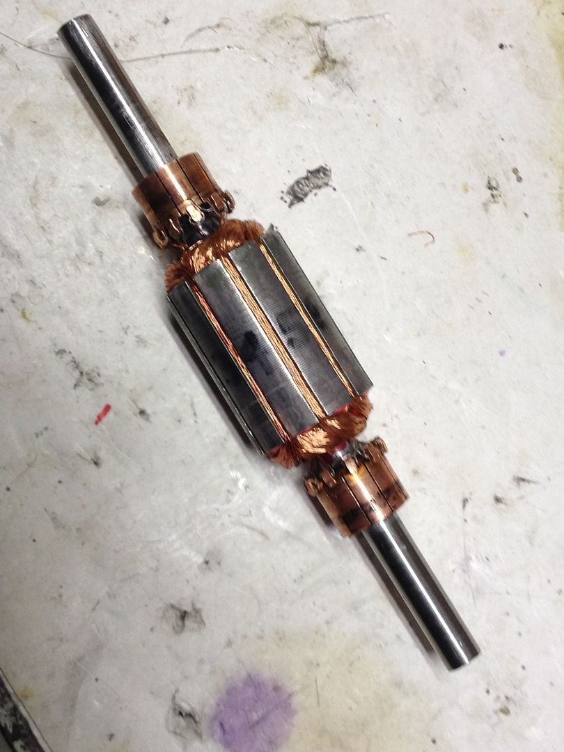


                    Enough room for the wooden stays or hedges I like to use now. I need to redesign the wire exit ports and the way the brush endplates fasten to the motor body to give me easy tuning. When following Ufo's directions about winding one coil and then winding the coil on the opposite side next, it has given well balanced rotors...
                    Last edited by sampojo; 04-10-2015, 03:36 AM.
                    Up, Up and Away

                    Comment


                    • Added my theory for simple comparison of motor results to post #7416 http://www.energeticforum.com/272203-post7416.html

                      Happy Hunting

                      mark

                      Comment


                      • Originally posted by HuntingRoss View Post
                        Added my theory for simple comparison of motor results to post #7416 http://www.energeticforum.com/272203-post7416.html

                        Happy Hunting

                        mark
                        Mark

                        By using group coils, one pole bigger than the magnet/5 rotor poles on the SC7, you were able to meet the OEM with gearing for torque and have extra RPMs.

                        OEM~1.13A~3840rpm~27W~8.8kg
                        SC5~3.60A~13128rpm~90W~5.7kg
                        SC6~2.13A~8506rpm~53W~5.9kg
                        SC7~1.59A~6772rpm~40W~7.5kg
                        Do you have enough equipment/power supply to run a watts for watts comparison on the OEM and SC7?

                        Will you try the All North Pairs next? It's the next logical indicator step.
                        A.)pairs coils same size as magnet/4 poles
                        B.)pairs coils one pole bigger than the magnet/5 poles


                        Keep it Clean and Green
                        Midaz

                        Sorry, I forgot that you did some pair testing in the past but from your notes and images, your test results were invalid because the time was incorrect.
                        Attached Files
                        Last edited by Midaztouch; 04-07-2015, 11:50 AM.

                        Comment


                        • Originally posted by Midaztouch View Post
                          Mark

                          By using group coils, one pole bigger than the magnet/5 rotor poles on the SC7, you were able to meet the OEM with gearing for torque and have extra RPMs.


                          Do you have enough equipment/power supply to run a watts for watts comparison on the OEM and SC7?

                          Will you try the All North Pairs next? It's the next logical indicator step.
                          A.)pairs coils same size as magnet/4 poles
                          B.)pairs coils one pole bigger than the magnet/5 poles


                          Keep it Clean and Green
                          Midaz

                          Sorry, I forgot that you did some pair testing in the past but from your notes and images, your test results were invalid because the time was incorrect.
                          Hi Midaz

                          I have wound nearly every permutation of groups, poles and pairs...and SC7 is the closest to the OEM torque I have managed and after the last two days of testing the OEM and SC7 on the 120 tooth sprocket I think I might be able to squeeze a little more torque from an SC7 re-wind.

                          I wound #6 all north versions of the 2 comm Asymm motor (Beast) with a couple of type variations in between...none came close to the OEM. All had amazing revs but not sufficient to pass the test.

                          I now have #9 N/S versions of the SC motor and one type variation and SC7 is the front runner...so I'm going to try and perfect that for the moment.

                          I also accept that the SC wind is a hybrid, a compromise on the Asymm method, but its advantages are what makes it simple for people with no motor experience. There is no need for a sacrificial motor, no shafts to press out and press in, no comm to prize off and press on and align. Just one set of extra brushes and rewire. The one thing it absolutely can't do is the all north configuration.

                          This is a limiting factor, but on the up side, it does avoid magnetic drag as the north coil leaves the south stator. And, there must also be the acceptance that an all north motor does manifest south poles on the rotor poles between the energised coils. This is one of the reasons why I have pursued this method because it reinforces what occurs naturally in the all north motor anyway.

                          Not sure what you mean by 'watt for watt comparison' that I haven't already provided. The OEM ~ SC7 comparison is 27W ~ 40W.

                          I fitted the 120 tooth sprocket to the 12.5" dirt bike wheel and the SC7 took it to 495 rpm which gives a no load speed of around 17mph...the amps were just as the 24v test previously, 1.53A. The OEM took it to 277rpm @ 1.05A.

                          It demonstrates that gearing does not affect the power characteristics of the motor. The other tweak for the gearing is to introduce a transfer gear which will push the gearing from 13.3:1 to 22:1 which will enhance the torque and bring the no load speed down. Once I have a platform to road test the gearing arrangement I can remove the transfer gear if the road speed is too low.

                          Happy Hunting

                          mark

                          Comment


                          • Originally posted by Midaztouch View Post
                            Sorry, I forgot that you did some pair testing in the past but from your notes and images, your test results were invalid because the time was incorrect.
                            That image of the motor that you linked was re-wound with the correct timing...you'll remember that UFO apologised for misleading me on the timing mark for the motor.

                            Happy Hunting

                            mark

                            Comment


                            • Timing Adjustment

                              @all
                              The most important lesson that I have learned this week in the Battle of the Windings is how critical the timing is to all of the asymmetrical type of motors. In every case 5 degrees of timing can radically change the performance of the motors. I come from the background of automotive technology and have always known that timing is so critical in an automobile engine. I never thought that it would be so critical in an electric motor. I have been testing and retesting the timings on these machines all week and have found the results almost unbelievable as to the differences that it makes. The one advantage that my replications have over most that I have seen is that I can retard the timing up to 10 degrees and in most of my embodiments advance it up to 10 degrees. The exception being my first embodiment in which I can only get about 5 degrees advance. When the sweet spot is found the amps in plummet like a rock. You will see this when I release the videos upon completion of all of the timing tests. This is the second time that I am working through the tests. I made an error in the first run because of my unfamiliarity with the clamp ammeter. I noticed on some of the tests the ammeter was retaining a reading and not zeroing out before the test. I reread the manual and there is a button for relative (rel) on the meter that zeros out the reading. This brought down the amp readings on all of the timing tests. When you see how the all north performs against the stock gold mine motor you will be amazed. In the second timing test the amps drop from 850 milliamps to 110 milliamps!!!! The RPM dropped to slightly above 8300 rpm. This compared to the retested stock motor which came in slightly above 3600 rpm at right around 300 milliamps. And still maintained good torque features. I cannot think of a good measuring device for the torque of these motors. The shafts are only 4 millimeters in diameter and won't hold much in vibration without bending. You can take my word that in the grab test they do just fine. Now this is at 12 volts. Way below the maximum voltage for the stock motor and who knows what the maximum voltage of the redesigned motor will be. 1/3 of the amperage in and over double the RPM and still has respectable torque. The question that needs to be answered is how have you handled the timing of the motor??!! If you are having high amp readings I challenge you to make an embodiment like I have to be able to experiment with the timing. These motors are still in the experimental stages and need to be thoroughly tested in various timings. The results will astound you!!!!

                              Cheers

                              Garry
                              Last edited by GChilders; 04-08-2015, 12:50 AM.

                              Comment


                              • Mark,

                                Your timing was incorrect on this one also and you used the split rotor. When did you do the testing agian and post the results?
                                Attached Files
                                Last edited by Midaztouch; 04-08-2015, 01:05 AM.

                                Comment

                                Working...
                                X