 Tweet
Tweet
Hybrid Sym-Asym Motor
Hi to everyone. I've been quiet but not inactive. I submit for peer review, the SC#5.
Schematic at the end of this post and photos to follow shortly.
The OEM motor -
MY6812 24v 120w
12 poll 2 stator 1 commutator 2 brushes
0.53mm guage wire
A symmetrical motor has one length of wire wound with coils in series, the wire returning to the origin.
The route for current is one direction along two paths from brush to brush. If you picture the brushes at 3 and 9 o'clock, path 1 passes through 12 o'clock and path 2 passes through 6 o'clock.
This embodiement retains the original structures of the OEM replacing only the wire and adding 2 brushes.
--S--
Title explained -
The SC#5 (single commutator build 5) embodies the symmetric principle with one wire wound in coils in series returning to the origin. It departs from the principle as only 2no commutator sectors are so wired. The remaining comm sectors are wound as independent pairs giving a total of 6no pairs.
In this way pairs are isolated after leaving their Motor brushes and are free to deliver their energy to the Generator
brushes just prior to being re-energised 180o advanced.
For this reason I have retained the description Asymmetric and hence HYBRID.
--S--
Winding.
3 coil groups in pairs. 11 turns 3 poles per coil of 0.5mm wire. Wound for CW rotation.
Starting with P1 at 9 o'clock. Moving clockwise wind for north coil repulsion 3 coil groups. On completion of the first 3 coils hook over P7 comm and still moving clockwise wind another 3 coil groups (all coils are wound clockwise as seen from the front with shaft seen behind the coil). On completion of the second 3 coils hook over P1 comm and twist the two ends together tightening against the P1 tab. If this is not clear in the description, schematic below should help. This is one Pair of 3 coil groups.
Pairs are as follow -
P1 / P7
P4 / P10 (P4 is perpendicular to P1)
P2 / P8
P5 / P11 (P5 is perpendicular to P2)
P3 / P9
P6 / P12 (P6 is perpendicular to P3)
This winding pattern gives a very 'flat' build, meaning the build up of wire towards the commutator is minimised and wire length is more balanced around the armature as the wind progresses.
The coils on the 12 o'clock side energise North and the coils on the 6 o'clock side energise South. Both are in repulsion to their stators.
The geometry of the 12 pole motor places the P1 Coil 1 bisector approximately 20o past the north stator bisector. The geometry of this motor doesn't allow for that figure to be greatly reduced. Reduction is crudely adjusted depending on poles grabbed per coil. Finer tuning would require re-engineering of the brush mounting plate.
I tested each pair after winding at 5v PSU and measured amps -
Pair 1 - 1.92A
Pair 2 - 2.46A
Pair 3 - 2.44A
Pair 4 - 2.41A
Pair 5 - 2.38A
Pair 6 - 2.09A
A feel (literally) for torque was assessed with each pair by pinching the shaft between my fingers and I was surprised from
coil one onwards the reluctance for the motor to stall.
Bench test SC#5 -
5v @ 2.09A @ 2700rpm rising to 2800rpm
10v @ 2.30A @ 6048rpm
Bench test OEM -
5v @ 1.18A @ 763rpm
10v @ 1.18A @ 1546rpm
--S--
Static Scooter tests :
The motors were plugged into the controller only. Not driving the rear wheel.
SC#5 -
25.1v @ 3.6A @ 13,128rpm (90.4W)
OEM -
25.1v @ 0.88A @ 3840rpm (22W)
With the scooter tethered to a static object (washing machine) with a scale balance -
SC#5 5.7kg
OEM 8.525kg
This is in effect a static stall torque test measured at the radius of the wheel.
Findings -
The static test places the SC#5 at 70% of the OEM torque.
The 5v, 10v and 24v tests places the SC#5 at around 3-4x the revs and 2x the amps.
The motor drives the back wheel through final gearing. The shaft sprocket is a 16 tooth the wheel sprocket is 88 tooth giving
5.5:1. The OEM no load free spinning speed is 640rpm.
--S--
Adding Brushes -
The OEM brush holders are brass with 4no tab feet bent under the mounting board. My donor motor was stripped of its brushes and I drilled and mounted into the SC#5.
As the repulsion coils rotate off their Motor brushes the collapsing north and south coils continue to repel but become increasingly attracted to their opposite magnet. Positioning the Generator brushes is set to allow the incoming attractive coils to assist rotation for as long as possible, accordingly they are set at P3 and P9.
Bench test V out -
5.4v PSU no load
5.02v in @ 2.32A. 3.89v out @ 2706rpm
10.28v PSU no load
9.93v in @ 2.49A. 9.93v out @ 5919rpm
The additional brushes added some load / resistance. These figures settle a little outwith the snapshot of testing.
--S--
Running a load off the SC#5 output -
5.38v PSU
SC#5 4.94v @ 2.28A @ 2692rpm (11.3w) @ 3.69v out
Connect OEM load to SC#5 output
SC#5 4.96v @ 2.47A @ 2644rpm (12.3w) @ 3.33v out
OEM 3.33v @ 0.5A @ 475rpm (1.7w)
10.33v PSU
SC#5 9.96v @ 2.35A @ 5870rpm (23.4w) @ 7.82v out
Connect OEM load to SC#5 output
SC#5 9.89v @ 2.51A @ 5923rm (24.8w) @ 7.43v out
OEM 7.43v @ 0.78A (5.8w) @ 1115rpm
(note: the motor was warming and the 5870rpm had risen to above 6000rpm)
Scooter 24v batteries and controller -
OEM 120w : 25.1v @ 0.88A @ 3840rpm (22W)
OEM 450w geared motor connected to controller : 24v @ 2.63A @ 471rpm (63W)
(note: reference to OEM in all other cases is OEM 120w motor described at the top of this post)
SC#5 24v @ 3.55A @ 13,025rpm (85.2w) @ 13.5v out
Connect OEM 120w load to SC#5 output
13.5v @ 0.93A @ 1990rpm (12.6W)
Connect OEM 450w geared motor load to SC#5 output
13.5v @ 2.33A @ 242rpm (31.5W)
Despite the power hungry nature of SC#5 I'm interested to see that 31W was returned at the output. I will need to rig the twist grip on the scooter to free up my hands for testing the change in performance of the SC#5 when the load is added. From the 5v and 10v results the difference may be very small and this would be a significant use to balance the disparity between the OEM and SC#5 current draw.
--S--
THEORY.
The shortfall in SC#5 torque at 24v can be adjusted by varying the final drive ratio to bring it up to the OEM benchmark and thereby trading revs for torque.
The OEM @ 24v @ 3840rpm @ 5.5:1 delivers 640rpm at the wheel. (assuming some frictional losses)
If the SC#5 @ 10v @ 6000rpm were to deliver 640rpm at the wheel the final drive ratio would be 6000/640 = 9.3:1
With a 16 tooth drive gear the final sprocket would be 16x9.3 = 149 teeth @ 3mm pitch = 447mm belt = 142mm dia.
The scooter wheel is a standard 5.5" 138mm dia so a gearing compromise would be required.
Assume 5" 127mm dia = 400mm circumference @ 3mm pitch = 133 teeth : 16 = 8:1 final drive = 750rpm
In theory then, modifying the 88 tooth sprocket to 133 tooth, the SC#5 might match the OEM torque and have a minor advantage in revs @ 10v (not 24v).
However I think the gearing adjustment will only compensate at 24v in which case there is a large rev differential which is likely to be a troublesome feature within a small scooter platform.
The more likely conclusion is the 13k revs @ 90watts (no load) will benefit from significant gearing down to raise the torque for a larger diameter wheel.
Otherwise it is hard to justify 90W as a starting point compared to the OEM's 22W although getting 31w or more on the output is useful compensation.
--S--
Proposed Field Tests.
Once I have modified the rear sprocket the 2no 12v batteries connected in series will be wired in parallel and the SC#5 will be tested against the OEM for speed and endurance @ 12v.
Happy Hunting
mark
[IMG]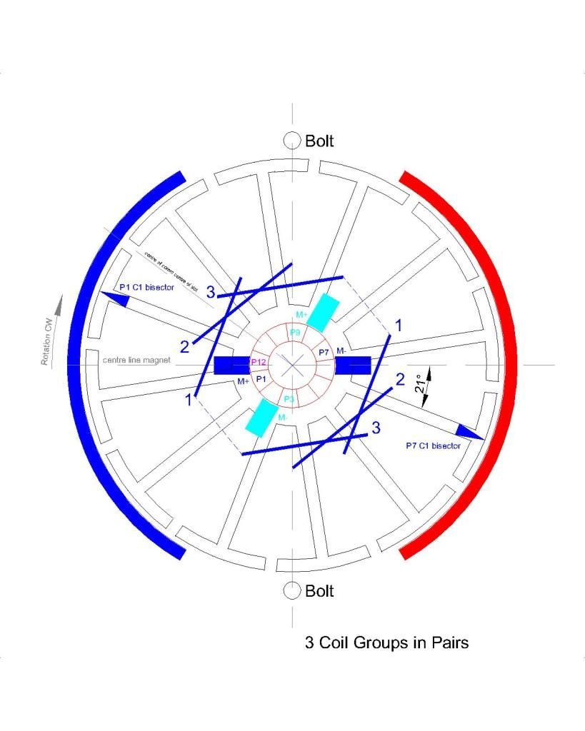 [/IMG]
[edit: Try as one does to get things correct...The schematic should show the P7 coils in red]
--S--
26th Feb 2015 - Photo upload
[IMG]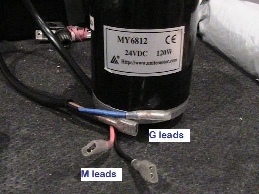 [/IMG]
[IMG]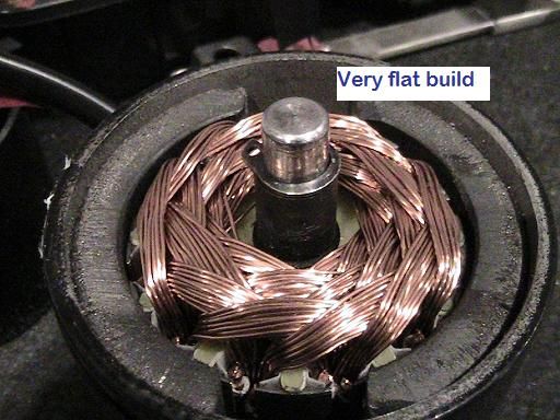 [/IMG]
[IMG]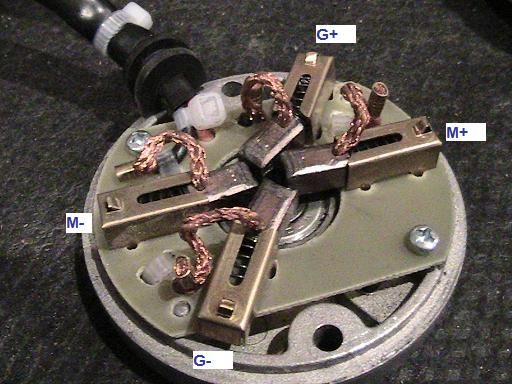 [/IMG]
[IMG]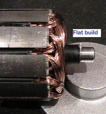 [/IMG]
[IMG]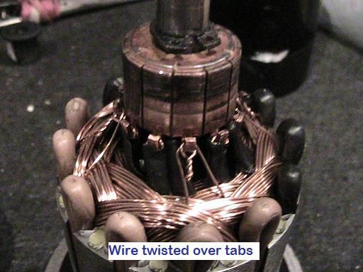 [/IMG]
--S--
28th Feb 2015 - SC#6 Build and Test Results
So today I chopped one new OEM and wound it as follows -
3 - 4 pole coil groups in Pairs - 20 turns per coil of 0.425mm wire. Schematic and photos to follow. Scooter torque test tomorrow.
Something as simple as organising the pairs as described at the top of this post allows me to easily get an extra 4 turns per coil over my previous 16 which was a struggle.
Results -
5.39v PSU no load
5.05v @ 1.33A @ 1713rpm. (6.72w). Vout 4.79v
10.35v PSU no load
10.23v @ 1.48A @ 3554rpm. (15.14w). Vout 10.44v [Note. I double checked that result - the Vout exceeds the Vin]
--S--
Curious with the increase in voltage I just completed a load test -
10.36v PSU no load
SC#6 ~ 10.14v @ 1.5A @ 3402rpm @ 10.51 Vout [15.2w]
Connect SC#5 to SC#6 Vout
SC#6 ~ 9.92v @ 2.80A @ 3071rpm @ 8.36 Vout [27.78w]
SC#5 ~ 8.36v @ 1.84A @ 4803rpm [15.38w]
Allowing SC#5 to warm up
SC#5 ~ 8.36v @ 1.60A @ 4810rpm [13.38w]
SC#6 running no load @ 15.2w rising by 12.58w under load which is less than the power being used by SC#5. Perhaps someone can explain that. I will check this again tomorrow when I conclude the scooter torque test.
--S--
29th Feb 2015 - Static Scooter Test, Output load tests and photo of build.
26.5v @ the scooter controller output.
SC#6 ~ 24.7v @ 2.13A @ 8506rpm @ 26.6v out [52.6W] No load
Connect SC#5 to SC#6 output
SC#6 ~ 23.5v @ 3.87A @ 8015rpm @ 26-40v out [90.95W] The output was fluctuating a lot, this doesn't happen with the OEM. A scope of this output would be interesting.
SC#5 ~ 26-40v @ 2.52A @ 10,878rpm [notional watts 65W]
Connect OEM 450W to SC#6 output
SC#6 ~ 23.5v @ 4.09A @ 8054rpm @ 22.2v out [96.1W]
OEM 450w ~ 222.2v @ 2.62A @ 442rpm [58.16W]
Once again the SC#6 under load takes less power than the SC#6 no load + SC#5 load. Does anyone have a theory on this ?
Notice also the OEM 450w pulling 58W compared to SC#5 load @ 31W.
SC#6 static pull (torque) test 5.9kg (OEM 8.8kg)
[IMG]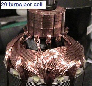 [/IMG]
--S--
[IMG]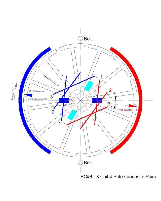 [/IMG]
--S--
2nd March 2015 - SC#7 build commenced. 3 coil 5 pole groups in Pairs - 20 turns per coil. Test results for pairs as build progresses -
Pair 1 - 5.21v @ 1.0A @ 934rpm
Pair 2 - 5.14v @ 0.98A @ 1150rpm
--S--
Continued at Post http://www.energeticforum.com/272203-post7416.html as this post exceeds 12000 characters.
Happy Hunting
mark
Hi to everyone. I've been quiet but not inactive. I submit for peer review, the SC#5.
Schematic at the end of this post and photos to follow shortly.
The OEM motor -
MY6812 24v 120w
12 poll 2 stator 1 commutator 2 brushes
0.53mm guage wire
A symmetrical motor has one length of wire wound with coils in series, the wire returning to the origin.
The route for current is one direction along two paths from brush to brush. If you picture the brushes at 3 and 9 o'clock, path 1 passes through 12 o'clock and path 2 passes through 6 o'clock.
This embodiement retains the original structures of the OEM replacing only the wire and adding 2 brushes.
--S--
Title explained -
The SC#5 (single commutator build 5) embodies the symmetric principle with one wire wound in coils in series returning to the origin. It departs from the principle as only 2no commutator sectors are so wired. The remaining comm sectors are wound as independent pairs giving a total of 6no pairs.
In this way pairs are isolated after leaving their Motor brushes and are free to deliver their energy to the Generator
brushes just prior to being re-energised 180o advanced.
For this reason I have retained the description Asymmetric and hence HYBRID.
--S--
Winding.
3 coil groups in pairs. 11 turns 3 poles per coil of 0.5mm wire. Wound for CW rotation.
Starting with P1 at 9 o'clock. Moving clockwise wind for north coil repulsion 3 coil groups. On completion of the first 3 coils hook over P7 comm and still moving clockwise wind another 3 coil groups (all coils are wound clockwise as seen from the front with shaft seen behind the coil). On completion of the second 3 coils hook over P1 comm and twist the two ends together tightening against the P1 tab. If this is not clear in the description, schematic below should help. This is one Pair of 3 coil groups.
Pairs are as follow -
P1 / P7
P4 / P10 (P4 is perpendicular to P1)
P2 / P8
P5 / P11 (P5 is perpendicular to P2)
P3 / P9
P6 / P12 (P6 is perpendicular to P3)
This winding pattern gives a very 'flat' build, meaning the build up of wire towards the commutator is minimised and wire length is more balanced around the armature as the wind progresses.
The coils on the 12 o'clock side energise North and the coils on the 6 o'clock side energise South. Both are in repulsion to their stators.
The geometry of the 12 pole motor places the P1 Coil 1 bisector approximately 20o past the north stator bisector. The geometry of this motor doesn't allow for that figure to be greatly reduced. Reduction is crudely adjusted depending on poles grabbed per coil. Finer tuning would require re-engineering of the brush mounting plate.
I tested each pair after winding at 5v PSU and measured amps -
Pair 1 - 1.92A
Pair 2 - 2.46A
Pair 3 - 2.44A
Pair 4 - 2.41A
Pair 5 - 2.38A
Pair 6 - 2.09A
A feel (literally) for torque was assessed with each pair by pinching the shaft between my fingers and I was surprised from
coil one onwards the reluctance for the motor to stall.
Bench test SC#5 -
5v @ 2.09A @ 2700rpm rising to 2800rpm
10v @ 2.30A @ 6048rpm
Bench test OEM -
5v @ 1.18A @ 763rpm
10v @ 1.18A @ 1546rpm
--S--
Static Scooter tests :
The motors were plugged into the controller only. Not driving the rear wheel.
SC#5 -
25.1v @ 3.6A @ 13,128rpm (90.4W)
OEM -
25.1v @ 0.88A @ 3840rpm (22W)
With the scooter tethered to a static object (washing machine) with a scale balance -
SC#5 5.7kg
OEM 8.525kg
This is in effect a static stall torque test measured at the radius of the wheel.
Findings -
The static test places the SC#5 at 70% of the OEM torque.
The 5v, 10v and 24v tests places the SC#5 at around 3-4x the revs and 2x the amps.
The motor drives the back wheel through final gearing. The shaft sprocket is a 16 tooth the wheel sprocket is 88 tooth giving
5.5:1. The OEM no load free spinning speed is 640rpm.
--S--
Adding Brushes -
The OEM brush holders are brass with 4no tab feet bent under the mounting board. My donor motor was stripped of its brushes and I drilled and mounted into the SC#5.
As the repulsion coils rotate off their Motor brushes the collapsing north and south coils continue to repel but become increasingly attracted to their opposite magnet. Positioning the Generator brushes is set to allow the incoming attractive coils to assist rotation for as long as possible, accordingly they are set at P3 and P9.
Bench test V out -
5.4v PSU no load
5.02v in @ 2.32A. 3.89v out @ 2706rpm
10.28v PSU no load
9.93v in @ 2.49A. 9.93v out @ 5919rpm
The additional brushes added some load / resistance. These figures settle a little outwith the snapshot of testing.
--S--
Running a load off the SC#5 output -
5.38v PSU
SC#5 4.94v @ 2.28A @ 2692rpm (11.3w) @ 3.69v out
Connect OEM load to SC#5 output
SC#5 4.96v @ 2.47A @ 2644rpm (12.3w) @ 3.33v out
OEM 3.33v @ 0.5A @ 475rpm (1.7w)
10.33v PSU
SC#5 9.96v @ 2.35A @ 5870rpm (23.4w) @ 7.82v out
Connect OEM load to SC#5 output
SC#5 9.89v @ 2.51A @ 5923rm (24.8w) @ 7.43v out
OEM 7.43v @ 0.78A (5.8w) @ 1115rpm
(note: the motor was warming and the 5870rpm had risen to above 6000rpm)
Scooter 24v batteries and controller -
OEM 120w : 25.1v @ 0.88A @ 3840rpm (22W)
OEM 450w geared motor connected to controller : 24v @ 2.63A @ 471rpm (63W)
(note: reference to OEM in all other cases is OEM 120w motor described at the top of this post)
SC#5 24v @ 3.55A @ 13,025rpm (85.2w) @ 13.5v out
Connect OEM 120w load to SC#5 output
13.5v @ 0.93A @ 1990rpm (12.6W)
Connect OEM 450w geared motor load to SC#5 output
13.5v @ 2.33A @ 242rpm (31.5W)
Despite the power hungry nature of SC#5 I'm interested to see that 31W was returned at the output. I will need to rig the twist grip on the scooter to free up my hands for testing the change in performance of the SC#5 when the load is added. From the 5v and 10v results the difference may be very small and this would be a significant use to balance the disparity between the OEM and SC#5 current draw.
--S--
THEORY.
The shortfall in SC#5 torque at 24v can be adjusted by varying the final drive ratio to bring it up to the OEM benchmark and thereby trading revs for torque.
The OEM @ 24v @ 3840rpm @ 5.5:1 delivers 640rpm at the wheel. (assuming some frictional losses)
If the SC#5 @ 10v @ 6000rpm were to deliver 640rpm at the wheel the final drive ratio would be 6000/640 = 9.3:1
With a 16 tooth drive gear the final sprocket would be 16x9.3 = 149 teeth @ 3mm pitch = 447mm belt = 142mm dia.
The scooter wheel is a standard 5.5" 138mm dia so a gearing compromise would be required.
Assume 5" 127mm dia = 400mm circumference @ 3mm pitch = 133 teeth : 16 = 8:1 final drive = 750rpm
In theory then, modifying the 88 tooth sprocket to 133 tooth, the SC#5 might match the OEM torque and have a minor advantage in revs @ 10v (not 24v).
However I think the gearing adjustment will only compensate at 24v in which case there is a large rev differential which is likely to be a troublesome feature within a small scooter platform.
The more likely conclusion is the 13k revs @ 90watts (no load) will benefit from significant gearing down to raise the torque for a larger diameter wheel.
Otherwise it is hard to justify 90W as a starting point compared to the OEM's 22W although getting 31w or more on the output is useful compensation.
--S--
Proposed Field Tests.
Once I have modified the rear sprocket the 2no 12v batteries connected in series will be wired in parallel and the SC#5 will be tested against the OEM for speed and endurance @ 12v.
Happy Hunting
mark
[IMG]
 [/IMG]
[edit: Try as one does to get things correct...The schematic should show the P7 coils in red]
--S--
26th Feb 2015 - Photo upload
[IMG]
 [/IMG]
[IMG]
 [/IMG]
[IMG]
 [/IMG]
[IMG]
 [/IMG]
[IMG]
 [/IMG]
--S--
28th Feb 2015 - SC#6 Build and Test Results
So today I chopped one new OEM and wound it as follows -
3 - 4 pole coil groups in Pairs - 20 turns per coil of 0.425mm wire. Schematic and photos to follow. Scooter torque test tomorrow.
Something as simple as organising the pairs as described at the top of this post allows me to easily get an extra 4 turns per coil over my previous 16 which was a struggle.
Results -
5.39v PSU no load
5.05v @ 1.33A @ 1713rpm. (6.72w). Vout 4.79v
10.35v PSU no load
10.23v @ 1.48A @ 3554rpm. (15.14w). Vout 10.44v [Note. I double checked that result - the Vout exceeds the Vin]
--S--
Curious with the increase in voltage I just completed a load test -
10.36v PSU no load
SC#6 ~ 10.14v @ 1.5A @ 3402rpm @ 10.51 Vout [15.2w]
Connect SC#5 to SC#6 Vout
SC#6 ~ 9.92v @ 2.80A @ 3071rpm @ 8.36 Vout [27.78w]
SC#5 ~ 8.36v @ 1.84A @ 4803rpm [15.38w]
Allowing SC#5 to warm up
SC#5 ~ 8.36v @ 1.60A @ 4810rpm [13.38w]
SC#6 running no load @ 15.2w rising by 12.58w under load which is less than the power being used by SC#5. Perhaps someone can explain that. I will check this again tomorrow when I conclude the scooter torque test.
--S--
29th Feb 2015 - Static Scooter Test, Output load tests and photo of build.
26.5v @ the scooter controller output.
SC#6 ~ 24.7v @ 2.13A @ 8506rpm @ 26.6v out [52.6W] No load
Connect SC#5 to SC#6 output
SC#6 ~ 23.5v @ 3.87A @ 8015rpm @ 26-40v out [90.95W] The output was fluctuating a lot, this doesn't happen with the OEM. A scope of this output would be interesting.
SC#5 ~ 26-40v @ 2.52A @ 10,878rpm [notional watts 65W]
Connect OEM 450W to SC#6 output
SC#6 ~ 23.5v @ 4.09A @ 8054rpm @ 22.2v out [96.1W]
OEM 450w ~ 222.2v @ 2.62A @ 442rpm [58.16W]
Once again the SC#6 under load takes less power than the SC#6 no load + SC#5 load. Does anyone have a theory on this ?
Notice also the OEM 450w pulling 58W compared to SC#5 load @ 31W.
SC#6 static pull (torque) test 5.9kg (OEM 8.8kg)
[IMG]
 [/IMG]
--S--
[IMG]
 [/IMG]
--S--
2nd March 2015 - SC#7 build commenced. 3 coil 5 pole groups in Pairs - 20 turns per coil. Test results for pairs as build progresses -
Pair 1 - 5.21v @ 1.0A @ 934rpm
Pair 2 - 5.14v @ 0.98A @ 1150rpm
--S--
Continued at Post http://www.energeticforum.com/272203-post7416.html as this post exceeds 12000 characters.
Happy Hunting
mark


 ...Maybe this way you all could understand this important issue in our designs much better.
 .
.

Comment