If this is your first visit, be sure to
check out the FAQ by clicking the
link above. You may have to register
before you can post: click the register link above to proceed. To start viewing messages,
select the forum that you want to visit from the selection below.
I know the 5 pole motors are very small but... Is it possible to set the GEN BRUSHES near 120� from the input brushes? From the image below, the GENbrush would be on the left side at C3 & edge of P3. The gen coil would just start to leave the zero torque zone. 120� should give us some rotation assistance from the GEN brushes... Or 120� on the right side. The coils would sweep through the zero torque zone for best gen output. The will be slight magnetic drag either way you but 120� is is a good thing
I have built many replications with the goldmine motor. I have built a total of 5 embodiments and in the neighbor hood of 8 rotors. Rewinding is not a problem but building good embodiments is difficult. I ended up with a lot of machining that I think is out of the reach of most hobby shoppers. I believe that the best results have been from those who reworked the metal bodies. The plastic bodies look impressive but all seemed to lack the power of the metal embodiments. I could be wrong and there were other factors such as timing etc. Taking them apart without destroying the parts that you want to keep is the biggest challenge. Anyway keep at it. You will see some very interesting effects this next two weeks. I am going to post videos of my latest findings. I have not posted much in the last six months because I have been very building with many projects. I have taken on several new challenges and some of them include working with software for designing circuits, fixing bugs in the Radiant Motor program that I developed. Testing the all north wind. Working on Tesla Switches, Working through other battery charging systems including the one by Imhotep and a whole host of other stuff on my plate. I like testing before I post mainly because I have a very difficult time explaining to others what I am seeing as a problem and solutions. I have come up with a number of solutions that I think will be of interest to many here.
Per my last post I am doing a unipolar rotor (10 poles) for my quad stator motor body. 5 poles are wound and I am running a little behind methinks as far as totally filling the rotor with copper wire this go-round. I like to run on the + side of 1 ohms. I don't think my meters are that great at detecting 1 ohm, think they are +/- .3-.4 ohms~. I had used my alcatel wiring guide and calculations indicated bifilar 32ga, but that was coming in around 1.7ohm for my 18' of wire I am using. Not sure if the recycled Old-TV degausing wire I started using is actually 32ga, hard to get a good measurement with the mike. Going trifilar seemed perfect and the ohms were def. hovering around 1+. I used Ufo's Quad-Bent-Y 10 pole NS winding on the old rotor and 26ga, 16' filling it quite nicely. But it was .6-.7 ohm resistance, ran hot (130deg+) and was a candidate for burn-up. So I am trying to get away from that problem. I might have been able to go 20+' on a quad-filar 32ga. I probably need to go longer to compensate the lost resistance from adding an additional strand. But then going longer and thicker diameter might be the double whammy that won't fit. I dunno, am I compacting the wire after each coil much better now, confusing my past experience? Better pull out my spread sheet on this and rerun some more calcs with a better resistance value and thickness estimate....
Here are some pics, I'd like to get anyone's feedback.
Rotor is 50%, done, 5 poles. Don't look very filled up do they...
I want these motors to do some work for me, lotta test ideas.
UPDATE: takes about an hour to make the trifilar cable, wrap a pole, and compress windings. So like 10 hours time to wind this whole thing, so trying desparately not to undo things. However I may undo the last one, leaving 4 coils wound with 18" of trifilar, and balanced since winding alternate sides of rotor(2 and 2 then). I really seem to have underestimated how the litzed wires will lay. They fill every nook and cranny very efficiently apparently, and leave more room to add copper. So for a series of wires I think I will up to a quadfilar at about 22' and see how those look on the next few poles!!!
Been cogitating on this a while as I played auto-mechanic in the mundane world to keep things on track there. Looking at the pics I estimate the space is only 1/3 full and yet I am 50% wound, 5 poles done. Lotta space there. Looks like I got to bite the bullet and undo my windings. Using this site was helpful in its ft/ohm column: Wire Gauge: Nikola Tesla Page. Looking at 32ga, to get 1 ohm with quadfilar I gots to go to 24' (6'/ohm). Seems the multifilar is a lot more space efficient, spreading out to fill gaps while winding. So I am betting that the difference in performance could be quite notable, and I could be pleasantly surprised to fit 24' on this rotor. If it does not I will switch as necessary on the last winding to the trifilar 18' stuff... So multfilar windings may lay as flat (almost?) as the single gauge wire diameter when winding, would be my conclusion... I was assuming it would take the space equivalent to the total outside diameter of the equilateral triange on the trifilar, for instance. Going all-Tesla this weekend
This is Asymmetric Motors thread. You have come here many time with your stuff. And I've read some of it... It's best if you keep your work on your own thread. Please be respectful and delete your last post. I will delete this post soon.
you obviously do not read my stuff
I probably know more about 'asymmetry' than you do.
too bad wise guys like you do not want to learn from the PROVEN design of an asymmetrical motor that can turn a disc 4000 times its own size?
yes and this motor actually works unlike the asymmetrical designs that are still being designed on this thread?
why is that sir?
why are folks like you unwilling to learn?
I offered you a model for an asymmetrical motor that another researcher in another field suggests could be the model of the earth ... bio-mimicry suggests why not copy what powers the earth or the sun?
here is the deal I will make you, go ahead delete your comments, I will ignore you and you will ignore me.
sorry to have bothered you, my original offering was not nearly as offensive as your response....
My question is, Why would you want a High RPM motor without the torque under mechanical load
Group winds: High RPMs & lowest torque
Pair winds: High RPMs said & medium torque
Singular winds: Lower RPMs & highest torque
........
TORQUE: Singular winds -VS- Pair winds
16 turns each; magnet strength @ 18agw
Single coil= 16 turns
Pair coil= Two coils with 8 turns each
The SINGULAR coil's magnetic strength is a lot stronger than the PAIR coils combined. I think it was around 35% stronger! *I lost the magnetic torque calulator page but search for yourself and do the math
North Coils in the motor
Parameters: stator's length covers 5 poles = coil covers 5 poles.... timing of coil's bisector and stator's bisector = 5� Past the stators bisector
Motor: N stator length is 5 poles + free space is 2 poles + S stator length is 5 poles
Singular coil has 16 turns of 18agw @ 5� past the bisector of the North stator... 100% Repulsion force
Pair coils has two coils. The beginning pair coil has 8 turns of
Midaz, Midaz...
Please, think MORE before you keep writing, cause you are expressing a lot of "things" that are DEAD WRONG and pure NON SENSE guy!!
Group winds: High RPMs & lowest torque
Pair winds: High RPMs said & medium torque
What do you mean??!!
I have shown for over 2 years in a row...all the freaking motors have three or four times the torque as OEM's?
EVEN in the N-S PAIRS !
Have you done any so far of the ALL NORTH GROUPS OR PAIRS? even your imperial?...I know the answer...NOPE
So,I helped you with your idea of SINGLE COILS taking it into CAD, but NOW you are minimizing the properties of all asymmetric motors I have shown so far, in order to make prevail your single coil design above the line of everything written and shown here...
But the WORST part is...that it is just a THEORY, nothing else.
You are ASSUMING TOO MUCH Friend!
And with JUST A THEORY now you want for everyone who owns an Imperial to start your wind and forget about the rest.
Do Your Thing man, wind your Imperial with single coils, for God sake do it!...then come back with PROOF and show everyone here ALL those advantages you are claiming based on only smoke,ideas SO FAR...are REAL...
IT IS THE ONLY WAY TO GET RESPECT.
and you know AM A BUILDER...NOT MUCH OF A THEORIZER....like most of the Guys Replicating here are also builders, not Thinkers.
BY ALL MEANS I wish that it works better than any motor ever shown on Human History...but remember, such Extreme Claims REQUIRE EXTREME PROOF
And that Proof MUST COME ONLY from the "Theorizer"...No One else knows better than you, Trust me, I know what am saying.
And please, let anyone who wants to post related stuff here, to go ahead and do it...I am in charge to say who's Comments are or are NOT welcome here.
@Raphael: Please, keep posting that related stuff, is great!
I am TOO BUSY at the present time to do this RS Motor based on your suggestion...but am sure MANY here could do it in a fraction of a minute.
Principles for the Development of a Complete Mind: Study the science of art. Study the art of science. Develop your senses- especially learn how to see. Realize that everything connects to everything else.― Leonardo da Vinci
I see that you are still having problems in getting the winding to fit and calculating wire size that will fit and get the correct ohms. Earlier on in this thread, I showed how to calculate for wire but do not have the time to find it so I will give you a brief list of things to do before you start to wind.
Calculate the exact sq. inch or mm you have to wind in the channel. To get this correct you may have to make a drawing and divide it into several triangles and rectangles. A caliper is what to use for measuring, not a ruler.
Decide what ohm value you are going to end up with. Remember that if using multiple strand that you will need a special calculator to get close to the correct ohms, as it changes non lineally by the number of wires twisted.
Decide what ohm value you are going to end up with. Remember that if using multiple strand that you will need a special calculator to get close to the correct ohms, as it changes non lineally by the number of wires twisted.
Calculate the Sq. inch or mm of a wire you may use by using the diameter of the wire as the height and width.
Calculate the number of wires that will fit thru each slot. (divide Sq. inch of groove by Sq. inch of the wire.)
Calculate using these things, that when fully wound, if you will end up with the correct number of winds and correct ohms.
If not, change wire size or winds and if using multiple wire numbers of wires in each multi wire. It is not easy but will get you the motor you want first time and will fit. Also keep in mind that lentz wire will not carry as much amps as larger wire.
Prochiro
"Today's scientist have substituted mathematics for experiments and they wander off through equation after equation and eventually build a structure which has no relation to reality."
I've been helping and learning here, DAILY, for over 2yrs now. Through all of the ups and downs! Everything I know about DC motors, has come from the brilliant minds on energetic forum but mostly from our group! I've gotten to the point were I can look at an Asymmetric Motor design and know how to get the maximum performance out of it!
Midaz,
You have been here for two years, reading and going over mostly the Theoretical side...but not replicating from small models I have shown and taught here from the very beginning of this thread, this way you are getting only "half of the picture"...not the practice and experience that Real Builds deliver over time.
This is a simple DC Motor! I think it's fantastic! I know Asymetric Motors from all of the tests, successes and failures!.... Below are simple facts, that everyone here can except as facts with disputes. It's the difference between an average high schooler jumping -vs- an Olympic gold-medalist jumping.
I am not going to say here the "possible" wrong side of your idea...like I wrote before, we never know, we can never be sure something would "definitively" work or not work...ONLY building it, bringing alive from a paper theory or an idea, into a real built model demonstration.
The only thing I see wrong here is your attitude demonstrated in a couple of last posts.
It was not needed to minimize all the Real work displayed here for two years, in order to make prevail your new idea as the only winner...when you do not even have a $3.99 motor built based on that assumption.
This is not a Coca Cola versus Pepsi Cola marketing competition to reach more sales. This is an Open Source Science and Engineering Thread, not looking to make money out of it.
You starting this thread was and is a Great Honor for Nikola Tesla and HIS work!
Respectfully
Richard
Yeah, unfortunately Tesla had some "Ex-Assistants" who tried to steal his ideas (Marconi) or others who tried to "shine" on their own poor shimmering light, while trying to express what the Master did was full of mistakes (Edison)...both, the wrong attitudes.
There is a saying..."Ignorance is daring".
However, I wish you the best of luck in your new thread.
This would be my last post here dedicated to this issue.
Ufopolitics
Principles for the Development of a Complete Mind: Study the science of art. Study the art of science. Develop your senses- especially learn how to see. Realize that everything connects to everything else.― Leonardo da Vinci
I see that you are still having problems in getting the winding to fit and calculating wire size that will fit and get the correct ohms. Earlier on in this thread, I showed how to calculate for wire but do not have the time to find it so I will give you a brief list of things to do before you start to wind.
Calculate the exact sq. inch or mm you have to wind in the channel. To get this correct you may have to make a drawing and divide it into several triangles and rectangles. A caliper is what to use for measuring, not a ruler.
Decide what ohm value you are going to end up with. Remember that if using multiple strand that you will need a special calculator to get close to the correct ohms, as it changes non lineally by the number of wires twisted.
I believe you mean this formula: 1/R=1/R1+1/R2+...+1/Rn by nonlinear, if so no need to reply...
Calculate the Sq. inch or mm of a wire you may use by using the diameter of the wire as the height and width.
Calculate the number of wires that will fit thru each slot. (divide Sq. inch of groove by Sq. inch of the wire.)
Calculate using these things, that when fully wound, if you will end up with the correct number of winds and correct ohms.
If not, change wire size or winds and if using multiple wire numbers of wires in each multi wire.
It is not easy but will get you the motor you want first time and will fit. Also keep in mind that lentz wire will not carry as much amps as larger wire.
Prochiro
Yes I was assuming a hard triangular formation for a trifilar wire, but your way of doing it as a single strand calculation is quite proper as I see the strands spread out and lay flat as I wind. I always based it on ratios of areas starting with the number of winds that came off the old winding (if it did not fill the cavity I made an eyeball adjustment as far as percent filled, too). That has worked OK but assigning a hard geometric shape to a multifilar and computing its area is not right.
@ufo
I was looking at the new drawing of the wind that you and Midaz are proposing and this looks like you are winding it to be in repulsion mode, As in the R/S wind. Is this correct? It looks as if both coil 1 and coil 2 are receiving energy from the brushes with coil 1 bisector slightly off the bisector of the north stator and both being North poles in opposition to each other. But I noticed that you have reoriented your brushes and they are positioned differently than either of the R/S or all north embodiments. In the R/S embodiment the brushes are located in a line drawn across the separations between the N + S pole stators and in the all north embodiment the brushes are located in the position of the original embodiment. Here the brushes seem to be rotated cw about 15 degrees or so from the original embodiment. I have about 25 degrees of adjustment built in to both embodiments, these are actually goldmine 5 coil motors not R/S. I have stripped a number of motors recently in preparation for this project, I have been working on a number of other projects that I felt that I needed to get out of the way first.
Hello Garry,
Yes, correct, that first CAD was based on repulsion mode, however, it could be easily converted to higher percentage of 'Attract Mode'...watch:
[IMG][/IMG]
Vual�...is done...
The critical side here... is to disconnect C2 before its Bisector meets/aligns to the South Stator Bisector, otherwise they will tend to lock up, reducing performance. Note that C2 is almost disconnected by a 'hair' and still about five degrees to meeting Stator Bisector)
It is all 'relative' Garry, it could depend upon brush positioning without changing the commutator/element connections (like I did in above Diagram, by just rotating brushes)...or changing connections of Comm Elements, to be fired at the right angles to render either attract or repulse modes.
Repulse mode for some reason tends to increase amperage...but delivers greater torque and speed (look at it like 'the price we pay')...while Attract mode is the opposite in all parameters from attract.
My other question is how this affects the coil that the generator brushes are contacting on the opposite side of the rotor? I have noticed a significant increase in power in all of the winds when both of these coils are fed power in opposition to the polarity of the magnet.
Excellent question!
There is a 'Critical Angle' that must never be met between Input and Output (Motor & Generator sides), otherwise they could cancel or decrease strength between each others. That is the reason why I designed the 'Pairs' and the Groups of coils and not a Single Coil, we are 'bending' this way the magnetic field to avoid central shaft encounter...single coils are easier to encounter each others in the wrong angle, with the wrong set up, and orientation.
[IMG][/IMG]
If you notice in the Repulse mode Diagram positioning above, I am firing C1 and C2, while C4 is, which is exactly at 180� apart) at 'Plenum' contact (centered) in the output Generator Brush Element.
This means that C4 must be fed reversed from the way we feed Input (or the same way Gen Outputs 'Naturally') to assist rotation...so we will have that the orientation between the Two Single Motor Coils (C1-C2) and Generator Coil (C4) be:
Normally, if this is done in any magnetic arrangement, they will 'fuse' or attract together towards the center which -in this case- is the center shaft. Now, they could either magnify their strength by assisting each others (they do that in isolated cases, without a huge piece of steel in between), delivering a higher output at end poles, positively in this case, resulting in optimal performance...or, negatively, they could 'sink' all magnetic strength into the iron shaft embodiment, then loosing power at end poles...meaning, it MUST be tested to know which way they go, no 'Theory' works here but a real build my friend.
The best method is to test the theory and see how it works out. I recently broke one of the coils on my all north wind testing it to destruction in a test involving pulsing the cold electricity coil and using a 1000uf 120 volt capacitor to pump up the voltage from a 12 volt battery. I found that when I pulsed it leaving the duty cycle at about 20% the cap would pump up to almost 200 volts in a few seconds and then I had a switch that would allow the cap to empty the voltage into the all north motor as a load. Well this is obviously too much voltage and too much amperage for the design of this little motor but surprisingly it did not self destruct as I thought it would. In my mind I thought that it could not possibly handle the amperage and voltage that I was putting to it. It screamed in protest as the bushings handled the rpm load without getting too hot! Then it started running rough and I pulled it back apart. Expecting to see welded brushes and commutator I was quite surprised. No pitting no burning on either of the brushes or commutator. The roughness was from one of the wires breaking close to where it was connected to the commutator. I will rewind this with the original wind and continue with the other rewinds this week.
Cheers
Garry
Agree 100%, it must be tested out to see "if, or not" going to work.
Sorry I have not had the time to respond your PM, been busy, but it is very interesting, and I would answer as soon as I can.
Principles for the Development of a Complete Mind: Study the science of art. Study the art of science. Develop your senses- especially learn how to see. Realize that everything connects to everything else.― Leonardo da Vinci
I played the video from MIT "The New Universal Magnetic Theory" and am totally shocked that they state unequivocally black holes, dark energy, and dark matter to not exist. Funny how that shape of the magnetic field looks so like aether theory of matter with its spin and momentum postulates. And @Ufo this X shape of the field has implications for motors and winding possibly... But probably has been taken into account by such things as finding the best timing for a motor by experimentation.
Yes I was assuming a hard triangular formation for a trifilar wire, but your way of doing it as a single strand calculation is quite proper as I see the strands spread out and lay flat as I wind. I always based it on ratios of areas starting with the number of winds that came off the old winding (if it did not fill the cavity I made an eyeball adjustment as far as percent filled, too). That has worked OK but assigning a hard geometric shape to a multifilar and computing its area is not right.
Hello Sam,
I have seen your trifilar winding...it needs more strands friend, in order to generate together a huge magnetic field that would move that steel mass properly. I would say Six to Nine total strands of that fine wire.
Forget about their 'formation'...triangular, flat etc...twist them together to make like a single strand, or a cable, keeping a circular cross section pattern on the whole coil. And try to calculate in order to fill as much as you could the empty spaces in each slot.
You will then see the results...
Regards
Ufopolitics
Principles for the Development of a Complete Mind: Study the science of art. Study the art of science. Develop your senses- especially learn how to see. Realize that everything connects to everything else.― Leonardo da Vinci
Ok,Midaz, after we exchange some mails, I think I've got your idea and points.
This concept will work, no doubt about that, and I believe you are right about concentrating the magnetic field within a single coil will 'compact' (let me say it this way) the strength in lesser poles and will not split coils in two. This splitting deviates the bisector angle,or it becomes two bisectors...either one, and yes, it will weaken it somehow. I was going by flux transfer at common shared coils from one to the other...
I like to try this in a Radio Shack first...and see what it does.
If I got it right, the CAD Diagram should look like below:
[IMG][/IMG]
The only thing that must be done for it to be timed properly, would be to move for a short angle the brushes towards the rotation sense...like 5 to 10 degrees in order to avoid bisector engagement between stators and coil being fired.
Either move the brushes...or rotate both commutators to proper angle (counter to rotation) when assembling rotor, then have brushes at exact alignment to stators center.
So, yeah, let's give it a try friend...we never know, we are all experimenting here....and this is a 'Democracy' here in the Open Source spirit...
I like the simplicity of this configuration...and like I said...You are right, it makes sense...You may have seen what I have missed prior when dissecting the three poles and starting to walk into the All North concept.
For comparison purposes I will wind the RS Motor this way with the same number of turns and gauge, as I did when I made the video where N-S Pairs versus All North Pairs was made, differentiating from the all N Pairs that I would try to fit the two coils total turns into just one coil and two poles.
I will try to "squeeze" this new project in front of my BIG pile of pending work...
Regards Friend
Ufopolitics
Ufo,
Regarding this pole winding subtending 2 poles, I thought maybe the design would be more like the 3-pole where one coil would only be wrapped around one pole.
Would this coil design be completely wrong in your analysis?
As you know I have been working on 10-pole and 20-pole motors. If they are adapted to this design, one of the 10-pole coils would wrap 4 poles.
Would it be a bad Idea to wrap the inner 2 poles with a tighter coil all part of the same coil?
The way I figure it it is always a good thing to fill all space with copper wire, no?
Regarding this pole winding subtending 2 poles, I thought maybe the design would be more like the 3-pole where one coil would only be wrapped around one pole.
Sam,
That is what I thought also, but due to the Geometry of the Three Poles and other larger number of poles it can only be done this way, comprehending with the single coils about same area of stators circumference...otherwise, we will get 'clock movement' rotation speed if we do each coil per each single pole....imagine on the Imperial...we will need 56 Single little coils on each slot...the 'thing' will move like the 'Minute' needle on a clock...
Would this coil design be completely wrong in your analysis?
Not necessarily wrong, it would definitively work...on the overall behavior, result and performance I couldn't say till we build it.
As you know I have been working on 10-pole and 20-pole motors. If they are adapted to this design, one of the 10-pole coils would wrap 4 poles.
Would it be a bad Idea to wrap the inner 2 poles with a tighter coil all part of the same coil?
The way I figure it it is always a good thing to fill all space with copper wire, no?
Sam
That is a great idea Sam, turning inner centered small coils will definitively strengthen their magnetic field...it is the 'Pyramid' Magnetic Concept applied here. The only thing is...you would have conflict overlapping coils...since you have taken the slots space to do it...overlapping coils in any Motor (Symmetrical or Asymmetrical) will deliver a smoother rotation...while single, non overlapped coils are more 'static' over time, they will deliver a 'stepper motor like' rotation.
Have you ever built an Asymmetrical Three Poles?
If you have, then feed it at very low inputs...and notice how it "Steps"...of course the higher the speed the less noticeable the stepping effect.
Stepping effect should have great torque, but lower speed than overlapped coils.
Principles for the Development of a Complete Mind: Study the science of art. Study the art of science. Develop your senses- especially learn how to see. Realize that everything connects to everything else.― Leonardo da Vinci
I have seen your trifilar winding...it needs more strands friend, in order to generate together a huge magnetic field that would move that steel mass properly. I would say Six to Nine total strands of that fine wire.
Forget about their 'formation'...triangular, flat etc...twist them together to make like a single strand, or a cable, keeping a circular cross section pattern on the whole coil. And try to calculate in order to fill as much as you could the empty spaces in each slot.
You will then see the results...
Regards
Ufopolitics
Thanks Ufo.
So to get one ohm per coil on quadfilar 32ga, it needs 24' From the looks of the trifilar 50% done, I thought I could go to the quad. my QP10 winding took 16' of 26ga and that was stuffed, coming in light on the ohms about .7 ohm and it has a heating issue. a penta-filar winding 32ga would have to be 30' per coil. This is how long my double rotor motor wire coils are of 26ga, this style motor. Geez gonna take me a day just to do all of Dana's calcs to figure this out... but a 1ohm coil of 5 wires at 30' is getting pretty close or over the 26ga cross sectional area, from the seat of my pants, thus matching the needs of my double rotor size, not my single rotor designs. So it seems 6-9 wires could not possibly work, requiring over 36' min for 1 ohm. So here I ponder, delay wrapping, and calculate or do seat of pants... Hard to lay out more than 25' in my basement too. Guess I will go with trying to wrap one quad and see how it looks...
AHA, cross-sectional area comparison says quadfilar is near-perfect fit to match 26ga. Now 1 ohm is 24 feet vs my 16ft wrap jobs before on 26ga (less than an ohm) So obviously I am betting that the multifilar conservation of space will allow me to get only a 33% increase in length packed in... I think this might work...
G'day Glen UFO and the rest of the team
I have not done any thing more on Nessie or any other projects here as I am still trying to get my boat finished I keep getting and doing small jobs to get the finances to Firstly to complete My boat then I need about $1000.00 to purchase a battery for Nessie then I will finish her
I just looked in here to day to catch up in what is happening as tomorrow a friend has asked me to show his nephew what Motors I am working on
Kindest Regards to all
Kogs still here
 Tweet
Tweet


 [/IMG]
 [/IMG]
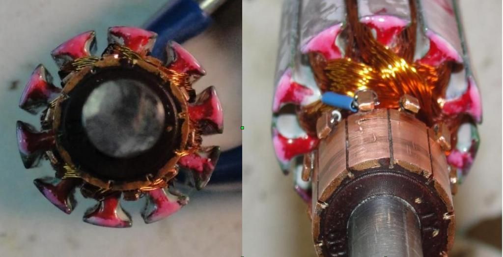


Comment