Announcement

Collapse
No announcement yet.

My Asymmetric Electrodynamic Machines

Collapse
X
 
  • Filter
  • Time
  • Show
Clear All
new posts

  • For the time being

    Hi UFO

    It wasn't clear in my last post, but the intention is to address the timing/amps draw in the next motor rebuilds and not this one.

    If this is the max power timing for this build of this motor then I will go with that.

    The brush boards are mounted on the motor end caps, timing adjustment would be by rotating the end caps given by the limits of the fixing bolts positioned between the north/south magnets.

    My uncertainty would be how to rotate both end caps to the same position to ensure perfect alignment...failing that...timing is defined by how inaccurately the two boards are positioned relative to each other. In practice I feel this margin of error is probably quite small.

    best regards

    mark

    Comment


    • UFO

      Thank you for your excellent explanation and diagrams. They are very clear and easy to follow. Yes, I understand the MAX Amps at/near TDC° Repulsion for a split second from a static position or stalling the motor to a dead stop.


      Sorry my thought and questions were not clear in my last post. I will try to clarify using your diagrams above

      This is my case...

      My thought was to set the timing as close as possible to 0°TDC "towards rotation" at the NSB/repultion . This would leave enough room to add one more coil per group. TDC° will bring the Max Density closer to the NSB, creating more torque.

      Instead of 3 coils in group1, have 4 coils in group1. This would increase the volume area/through out angles of the coils magnetic fields of G1and G2 magnetic fields combine. Also 4 coils would increase the strength of Max Density(over 25% vs 3coils??) when G1and G2 magnetic fields are overlapped/combine. Since the magnetic area is larger, it will be closer to the SSB/attraction... Further increasing the torque and RPMs without creating magnetic drag from SSB.

      *How do less turns per coil, for 4 coils per group, effect performance?

      *Does TDC° timing causes NN motors to reach absolute highest RPMs?

      *Do the attributes of setting the timing as close as possible to TDC outweigh the increase in AMPs?

      *Do the AMPs lower and stabilize at high RPMs because of space & time(timing) under load in NN Asymmetric Motors?

      *If the motors are set like the way I'm proposing, would you only have to adjust voltage to find the sweet spot for racing needs?

      *How does TDC° timing effect the gen action for producing energy?

      *For drag racing, could we reverse the polarity on the gen brushes to create a motor only or should we just disconnect the gen brushes?


      Sorry for so many questions, please answer what you can. Just trying to get a better understanding or what I can get away with! lol

      Keep it Clean and Green
      Midaz
      Last edited by Midaztouch; 10-25-2014, 01:30 PM.

      Comment


      • 'Beast' - Field test #2

        With the 'beast' wired directly to the batteries via a 40A power relay and protected by a 20A fuse I report the following -

        The starting temp of the motor body was 15.3 C rising to 28.6 C after 3 laps of approx 400 yards each.

        The run out is on a slight down gradient and the scooter was noticeably faster than the OEM. On the return leg the scooter slowed progressively to a stop before reaching the starting point. This was better than field test #1 where it popped the circuit breaker long before returning to the start position...but contrast with the OEM that did this circuit with no appreciable loss in performance.

        On returning home the beast was bench tested to see if any fault(s) had given rise to the problem -

        Rear wheel off the floor at full throttle is 965 rpm @ 4.5A rising to 16.8A stall speed.

        Swapped out for the OEM motor -

        At full throttle is 624 rpm @ 1.2A rising to 15.7A stall speed.

        For some inexplicable reason the 'beast' can not translate the superior bench test results to the ground.

        I checked continuity again. No faults.

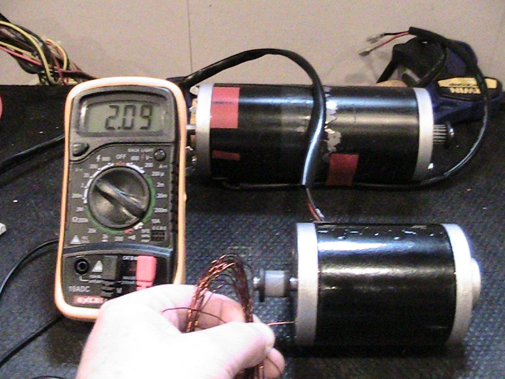
        I checked the 12 groups for resistance with my new meter and they all checked out at 2.3 - 2.4 ohms

        I have ordered equipment to rig a prony test and will report results in due course.

        Not so happy hunting

        mark

        Comment


        • Asym motor with ONE commutator

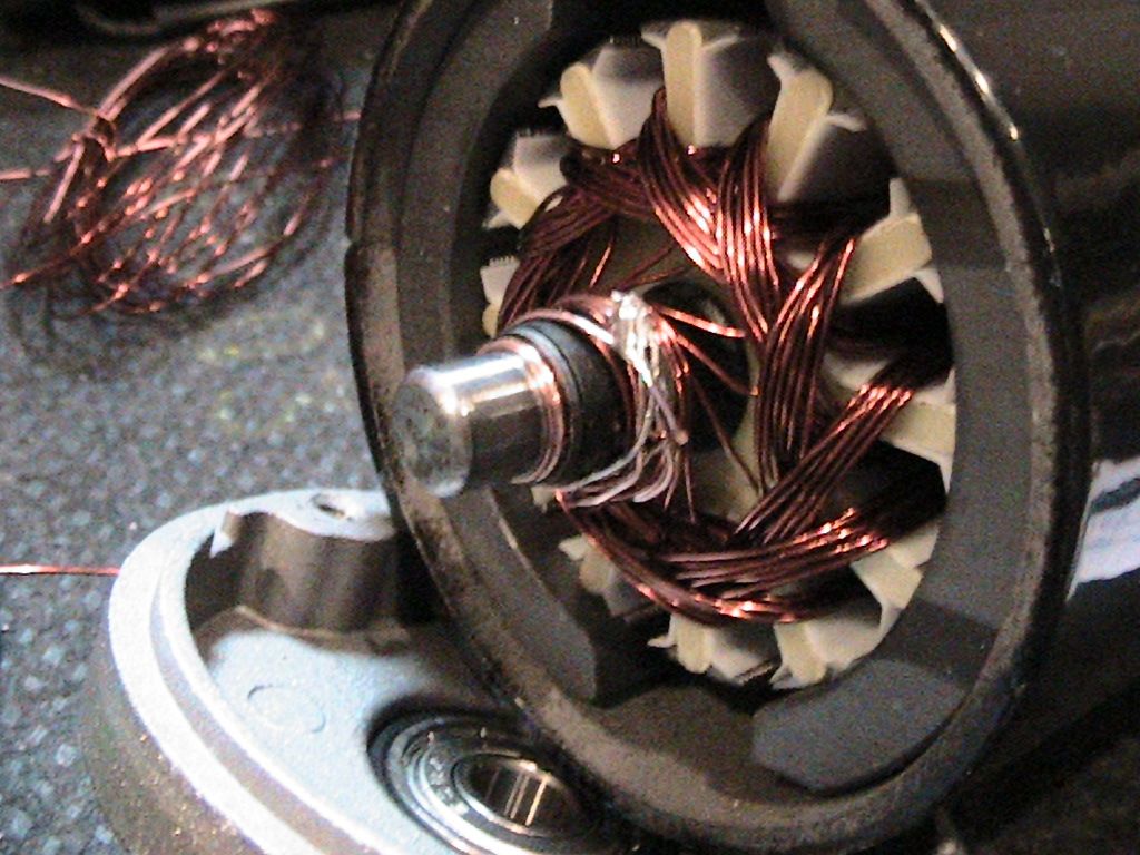
          So I stripped one of my new 24v 120w scooter motors to see if I could do a quick and dirty proof of one comm operation.

          OEM figures.
          Resistance -
          Leads 1.4 ohm
          Motor + Leads 4.6 ohm
          Motor (total 12 pole) 3.2 ohm
          Motor (6 pole) 1.6 ohm
          Longest coil length 3.7m

          I played with the timing on this motor pushing the G1 Coil 1, one pole further away from the north bisector.

          New figures.
          12 groups. 3 coils per group. 2 turns per coil.
          Two turns made it very quick to wind with an expected high amp draw.

          Connected to PSU - no load 5.39v.
          4.86v at 4.85A @ 2990 rpm with 2.05v at the output lead.

          So things to note.

          The bottom of the groups are all connected together and bonded to the shaft.

          The timing has affected the auto start of the motor...or maybe there are insufficient turns per coil...I don't have enough experience to know which one or both are responsible.

          It's a very easy build as it all fits within the OEM body and there is no second comm to fit. This took me 5 hours to strip build and test.

          The photo shows me grounding the body to start the motor.

          This method loses the ability to add the battery voltage to the output voltage as reported with the two comm motor. I suspect this is because the collapsing coils are lost to the shaft connection.

          Otherwise it seems to operate as a two comm asym motor.

          [IMG][/IMG]

          [IMG][/IMG]

          keep hunting

          mark

          Comment


          • Further tests

            Increasing the resistance of the lead wire to the motor body solves the auto start problem...and...running at 10.34v PSU no load -

            9.05v @ 9.87A @ 11,500 rpm and there is virtually no useful torque which is to be expected.

            Checked the armature after that many revs and everything is still in place.

            My guess for the OEM wire gauge is 0.5mm...calculation from the figures above puts the wire at approx 0.07 ohm/m which looks like 0.53mm or 0.56mm gauge.

            mark

            Comment


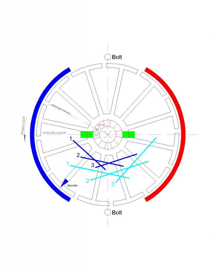
            • Timing diagram for the one comm asym motor

              [IMG][/IMG]

              Comment


              • Originally posted by HuntingRoss View Post
                [IMG][/IMG]
                Hi Mark

                We haven't used one comm. What are you trying to demonstrate?

                From your diagram, the max density is at the bolt. That would make the motor very weak. Instead of using the lap winding, try using NN pairs. Set the bisector of the coil closer to the Stator bisector.


                Midaz

                Comment


                • Single comm asym motor

                  Originally posted by Midaztouch View Post
                  We haven't used one comm. What are you trying to demonstrate?
                  Hi Midaz

                  Thank you for your questions.

                  When I connected my two comm motor to simulate a one comm arrangement by connecting the two bottom brushes together, I got the same performance with the same output also. Which begged the question - can we build a asym motor with one comm if we tie off the bottom wires to the shaft...the answer appears to be 'yes' unless I misunderstand some principles at play. This demonstrates the benefits of the asym motor allied with a simpler build. After all, it seems to me that unless people are prepared to build their own motors they're not going to get them any other way. These are not going to appear in your local hobby shop for example.

                  And...in the spirit of invention...it considers something which doesn't seem to have been considered (although I'm certain I have seen a photo of a similar build). Are any 'losses' in this design outweighed by the advantages ? And what are the 'losses' if any ?

                  I hope to find out.

                  Originally posted by Midaztouch View Post
                  From your diagram, the max density is at the bolt. That would make the motor very weak. Instead of using the lap winding, try using NN pairs. Set the bisector of the coil closer to the Stator bisector.
                  In response to UFO's post http://www.energeticforum.com/266307-post7164.html I moved the timing of my all North build to see if it offered any advantages. On this 'quick and dirty' build it seems to work OK although I can't comment on torque and amps as I have too few wires in the coil. Unless I misunderstood that post, we are aiming for the 'sweet spot' somewhere around the bisector of the two magnets and adjust back towards the north bisector to suit our particular performance requirements...ie. torque vs amps.

                  I'm going to re-wire this motor at the weekend to see if I can fit 20 turns per coil (all north) and judge its performance against the 'beast' (2 comm asym motor) and the OEM (1 comm sym motor).

                  Best regards

                  mark

                  Comment


                  • Hi Mark

                    There is a difference between the 3 images that UFO posted. The first image is different from the last two, 2 & 3 images. The poles are set differently. What image displays your pole setting accurately or did you made an accurate image of your set up?

                    Keep it Clean and Green
                    Midaz

                    Comment


                    • One Comm Asymmetry...

                      Originally posted by HuntingRoss View Post
                      Hi Midaz

                      Thank you for your questions.

                      When I connected my two comm motor to simulate a one comm arrangement by connecting the two bottom brushes together, I got the same performance with the same output also. Which begged the question - can we build a asym motor with one comm if we tie off the bottom wires to the shaft...the answer appears to be 'yes' unless I misunderstand some principles at play. This demonstrates the benefits of the asym motor allied with a simpler build. After all, it seems to me that unless people are prepared to build their own motors they're not going to get them any other way. These are not going to appear in your local hobby shop for example.

                      And...in the spirit of invention...it considers something which doesn't seem to have been considered (although I'm certain I have seen a photo of a similar build). Are any 'losses' in this design outweighed by the advantages ? And what are the 'losses' if any ?

                      I hope to find out.
                      Hello Mark,

                      I will tell you about this differences...and if you go back I had some long debate with a Member from Brazil related to the One Commutator structure, the only difference is that He , before even trying just one simple and small replication of the real two commutator structure, he jumped directly into this type of build.

                      Now Mark, you did great with your Typical Asymmetric Replication, except for the inconvenience of Road testing... so, there is a big difference here from previous Member I mentioned above, now, you can do as you please trying different set ups, like you have said, in the benefit of Science, Research and Development of an Open Source Material displayed here...to test different options and see if it does or does not work as well as the original design, following up and keep informing Us how it is doing.

                      The problems I see with the one commutator is that Coils, Pairs or Groups never have a complete "idle time" or off time, a brake...since Input Negative (bottom) will always be connected to Positive Output Coils (also on bottom end when using two commutators)...Radiant Energy will never be entering-assisting your Machine at Off Times Coils, Natural Reversal. And this is considering you are Inputting from normal top Positive and Negative through Bottom common or ground shaft...Now, if you will Input from both Top Terminals (Positive Input and Negative Output), ignoring/not connecting common shaft ground...then you have something very close to a typical Symmetrical Machine, except that Coils are NOT in COMPLETE series between ALL rotor Coils, but, by sequences of mating Pairs/Groups connecting through comm elements apart by 180º (in your case of two brushes, two stators...and 90º in Four Brush-Four Stators Systems).

                      Now, there is a big difference, when you use Two Commutators Structure and bridge-joint rear terminals through a wire from brush to brush...if you analyze this set up, there are just MOMENTARY shorting-connection between mating Coils, during time contacting brushes ONLY, after braking contact they go free and next mating Coils enters in.

                      On smaller number of Coils-Groups Machines there may not be a big difference, except when working on applications that require long operating hours...then that 'only/single' commutator will get really hot...and so the non stopping coils IF you are trying to collect and use the returned energy from the Output end.

                      And there are also some positive results on other members here long back...they were able to light up LED lamps and recharge small batteries through that Negative Input/Positive reversed Output at shaft/ground...you may want to try that...


                      In response to UFO's post http://www.energeticforum.com/266307-post7164.html I moved the timing of my all North build to see if it offered any advantages. On this 'quick and dirty' build it seems to work OK although I can't comment on torque and amps as I have too few wires in the coil. Unless I misunderstood that post, we are aiming for the 'sweet spot' somewhere around the bisector of the two magnets and adjust back towards the north bisector to suit our particular performance requirements...ie. torque vs amps.

                      I'm going to re-wire this motor at the weekend to see if I can fit 20 turns per coil (all north) and judge its performance against the 'beast' (2 comm asym motor) and the OEM (1 comm sym motor).

                      Best regards

                      mark
                      That is correct Midaz, it is like a "Neutral Position" where Mark is timing his machine at...right between both stators center......and it should draw much less amps there. From that point on towards South He would be timing it towards a higher Attraction Mode...decreasing to even more amps...but sacrificing power/torque and speed.

                      CORRECTION/EDIT 1: Mark, on your Diagram you are fully connected through motor brush/Comm Element to G2, not to G1...therefore, You MUST go by G2 Bisectors positioning and NOT by G1 Bisectors. Your Machine there is on very high Attraction Mode.


                      Kind Regards to both.


                      Ufopolitics
                      Last edited by Ufopolitics; 10-31-2014, 10:49 PM.
                      Principles for the Development of a Complete Mind: Study the science of art. Study the art of science. Develop your senses- especially learn how to see. Realize that everything connects to everything else.― Leonardo da Vinci

                      Comment


                      • UFO

                        Why do we need to use the attract mode with NN? When we made the N/S pairs, we use repulsion only. The torque and RPM were very high.

                        Just by the nature of the NN, the coil length would be shorter with the same amount of turns. And we could set the coil density closer to the stator bisector.

                        Keep it Clean and Green
                        Midaz
                        Last edited by Midaztouch; 11-01-2014, 12:05 AM.

                        Comment


                        • A little confused

                          Thanks UFO for the appraisal of the one comm motor. I figured there would be some down side...just not such a large one. If this avenue has already been explored without much success it is better to stop than carry on.

                          Originally posted by Ufopolitics View Post
                          CORRECTION/EDIT 1: Mark, on your Diagram you are fully connected through motor brush/Comm Element to G2, not to G1...therefore, You MUST go by G2 Bisectors positioning and NOT by G1 Bisectors. Your Machine there is on very high Attraction Mode.
                          I'm a little confused on the timing now. I thought I understood it...but now, not so much.

                          I understood it to be this - As G1 comm is coming onto the brush the G1 Coil 1 bisector had to be passed the north magnet bisector. This was my first timing diagram.

                          The diagram above has moved the G1 Coil 1 bisector one pole CCW as the G1 comm is coming on to the brush. This, I thought, reduced the amps.

                          Returning then, to the 'beast'...It seems to function very well on the table but not on the road with no apparent reason or solution.

                          regards

                          mark

                          Comment


                          • Originally posted by Midaztouch View Post
                            What image displays your pole setting accurately or did you made an accurate image of your set up?
                            Hi Midaz

                            The image above is the current set up and differs from my original image only by the fact that I progressed the first coil by one pole CCW.

                            regards

                            mark

                            Comment


                            • Mark

                              Are the comm segments accurate to the pole settings in your above diagram?

                              Keep it Clean and Green
                              Midaz

                              Comment


                              • Originally posted by Midaztouch View Post
                                Are the comm segments accurate to the pole settings in your above diagram?
                                Hi Midaz

                                Yes. The comm segments align with the slots.

                                Regards

                                mark

                                Comment

                                Working...
                                X