Announcement

Collapse
No announcement yet.

My Asymmetric Electrodynamic Machines

Collapse
X
 
  • Filter
  • Time
  • Show
Clear All
new posts

  • Search for parts

    Thanks Dana and UFO.

    Originally posted by Ufopolitics View Post
    I also noticed you did not used wire retaining hedges at slots, between two poles.
    I have done a reasonably thorough search for DC motor parts here in the UK and it is driving me insane. ‘Parts’ appears to mean brushes and bearings…I found one supplier for (one radius size only) arc magnets which are slightly smaller on the radius to my motor and about half or less on the arc angle…and that’s it. No comm supplier or laminates. I even had problems today finding M3 bolts so will be making my own to hold the casings together. Magnet wire is in abundance, nothing comes up for hedges and those nifty plastic stars at the top and bottom of the stack…who knows ?

    So any helpful clues on where to source this stuff would be gratefully received…especially hedges as I had a suspicion it could have been leakage out the slot that pulled the wire off.

    I also checked out Imperial motors and find no reference to kits so a link would be good please.

    Originally posted by Ufopolitics View Post
    For next winding, you could use a bit finer wire and add as many turns as you could fit there per each coil in the Group.
    I shall rewind this motor with more finesse using 0.425mm (solderable) so I can ensure proper connection and lever those tabs up for a good mechanical fix. I should be able to get 10m of wire per group. The wire is quoted at 0.121 ohms/m. Hopefully that sounds good ?

    Originally posted by Ufopolitics View Post
    Also could add several strands of even finer wire and that would strengthen your rotor magnetic fields without high amp draw.
    Apologies UFO, When you say add these…do you mean add them after the heavier wire or at the same time…bifilar style ?

    Originally posted by Ufopolitics View Post
    Please check on each group as you attach them at both commutator elements (upper-lower) with a continuity meter for ground short with the rotor metal between any of the two elements. They must be isolated from ground.
    You will not be surprised that I didn’t do this…but I will next time.

    Originally posted by Ufopolitics View Post
    I really enjoy seeing members like you!...that just get the hints, no matter what, goes for it... and get it DONE, and on top of that it runs excellent...
    Thanks UFO…I had a clear idea of what I wanted to achieve and I had studied your videos to try and embed this completely different methodology. When you consider that I did this with no background in the subject, no tools apart from a screwdriver to take the original motor apart and a soldering iron to put the new one back together…AND…copious amounts of insulation tape. It shows what can be achieved once the hard work has been done. The hard work being your invaluable input to this subject.

    Thank you all.

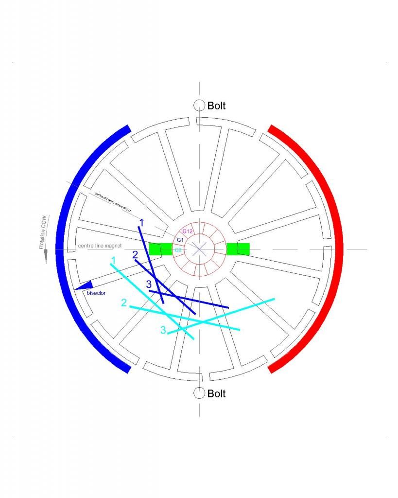
    Now I knocked this up at work today just to show the minor differences in UFO’s diagram and my motors geometry. This is how I wired it –

    12polemotor.jpg Photo by huntingross | Photobucket

    A described before the G1 comm is coming onto the brush with G1 Coil 1 bisector past the midpoint of the magnet.

    mark

    Comment


    • Originally posted by HuntingRoss View Post
      Thanks Dana and UFO.


      I have done a reasonably thorough search for DC motor parts here in the UK and it is driving me insane. ‘Parts’ appears to mean brushes and bearings…I found one supplier for (one radius size only) arc magnets which are slightly smaller on the radius to my motor and about half or less on the arc angle…and that’s it. No comm supplier or laminates. I even had problems today finding M3 bolts so will be making my own to hold the casings together. Magnet wire is in abundance, nothing comes up for hedges and those nifty plastic stars at the top and bottom of the stack…who knows ?

      So any helpful clues on where to source this stuff would be gratefully received…especially hedges as I had a suspicion it could have been leakage out the slot that pulled the wire off.

      I also checked out Imperial motors and find no reference to kits so a link would be good please.


      I shall rewind this motor with more finesse using 0.425mm (solderable) so I can ensure proper connection and lever those tabs up for a good mechanical fix. I should be able to get 10m of wire per group. The wire is quoted at 0.121 ohms/m. Hopefully that sounds good ?


      Apologies UFO, When you say add these…do you mean add them after the heavier wire or at the same time…bifilar style ?


      You will not be surprised that I didn’t do this…but I will next time.


      Thanks UFO…I had a clear idea of what I wanted to achieve and I had studied your videos to try and embed this completely different methodology. When you consider that I did this with no background in the subject, no tools apart from a screwdriver to take the original motor apart and a soldering iron to put the new one back together…AND…copious amounts of insulation tape. It shows what can be achieved once the hard work has been done. The hard work being your invaluable input to this subject.

      Thank you all.

      Now I knocked this up at work today just to show the minor differences in UFO’s diagram and my motors geometry. This is how I wired it –

      12polemotor.jpg Photo by huntingross | Photobucket

      A described before the G1 comm is coming onto the brush with G1 Coil 1 bisector past the midpoint of the magnet.

      mark
      Hello Mark,

      Yes, it is not a simple deal to search for motor parts...your best bet is to go to any motor repair shops around your area...they should have the source where to get some parts...also they may even give you some hedges or other parts that you will have to buy in cases from the wholesaler.

      A Couple of pages back is the Imperial Kit links...I will look for it.

      Another source are the "Goldmine Motors"...but they have smaller types than yours.

      The 0.4 mm wire should be fine, and yes, getting as much as you could per coil...of course, calculate that you will have enough room whenever wrapping and meeting each sides of the Spiral.

      When I said "adding several strands of much finer wire", I meant, yes, like "Multi-Filar" wires....and not on top of bigger wire.


      Good luck in your search around town...

      @ All the Members here: If any of you guys have handy the Imperial Link Kit, please post it here...as well as the Goldmine Motors Link...Thanks Guys!

      ...but make sure Mark, to tell Dyann (at Imperial) to pack it very well and tight, NO LOOSE SMALL PARTS INSIDE please!

      Still you will need a wire supplier near by...Imperial Kit comes without wires.


      Regards


      Ufopolitics
      Principles for the Development of a Complete Mind: Study the science of art. Study the art of science. Develop your senses- especially learn how to see. Realize that everything connects to everything else.― Leonardo da Vinci

      Comment


      • Mark
        Dyann is her name and you can search for all info by searching Dyann. Post 2709 has contact information and post 2685 has her e-mail.
        Dana
        "Today's scientist have substituted mathematics for experiments and they wander off through equation after equation and eventually build a structure which has no relation to reality."
        Nikola Tesla

        Comment


        • Application

          Thank you both for the extra info.

          Now. Applications for the beast I've built.

          Two things which I consider important, transportaion and energy.

          Applications need to be practical and/or fun.

          I have an old 500w petrol generator which I'm considering taking the engine off and seeing if this little thing can spin it up. It would produce 240v AC and it also has 12v DC output for battery charging. An obvious circular connection here.

          But I have elected to purchase the scooter that the original motor drives. This should be a pretty straight forward plug out / plug in. The little original motor is quoted at driving this thing (depending on terrain) at 20km/h and 20km on one charge. That seems impressive considering the quoted low torque and 2500 rpm top end speed at 24v.

          The new beast already has more torque and revs at 5v. This should be interesting. The scooter should be with me within a week. Stay tuned.

          mark

          Comment


          • Another question

            UFO recommends 'hedges' to close the slots.

            I have found these two options -

            Slot closures

            Enamelled Copper Wire,Motor Repair

            Slot wedges

            Enamelled Copper Wire,Motor Repair

            The first one describes what I want to do...the second one sounds like 'hedges'.

            The closures look like an OK price considering I'm getting 99m of stuff I'll never use and the wedges are way expensive.

            Helpful hints welcome

            mark

            Comment


            • Very Interesting Indeed!

              Originally posted by HuntingRoss View Post
              Thank you both for the extra info.

              Now. Applications for the beast I've built.

              Two things which I consider important, transportation and energy.

              Applications need to be practical and/or fun.

              I have an old 500w petrol generator which I'm considering taking the engine off and seeing if this little thing can spin it up. It would produce 240v AC and it also has 12v DC output for battery charging. An obvious circular connection here.

              But I have elected to purchase the scooter that the original motor drives. This should be a pretty straight forward plug out / plug in. The little original motor is quoted at driving this thing (depending on terrain) at 20km/h and 20km on one charge. That seems impressive considering the quoted low torque and 2500 rpm top end speed at 24v.

              The new beast already has more torque and revs at 5v. This should be interesting. The scooter should be with me within a week. Stay tuned.

              mark
              Hello Mark,

              Those are VERY interesting proposals you are planning there...and yes, it would be very exciting to see that!

              A 500 Watts Generator Head should not be such an ambitious Test or too heavy of a load for an Imperial All North.

              I love Scooters, small little vehicles that could haul A** and get you everywhere...very practical.

              Very soon I will be disclosing -through another Thread, since I don't want to bring more controversy here- a completely different set up for "A Completely different structured Generator"...no visible Lenz Effect ...and more and more......What am trying to say is...do not spent too much money in an Imperial just to run a very "Toxic Generator Type"...if you decide to buy an Imperial, plan to use it on a small EV or even an Electric Super Bike...

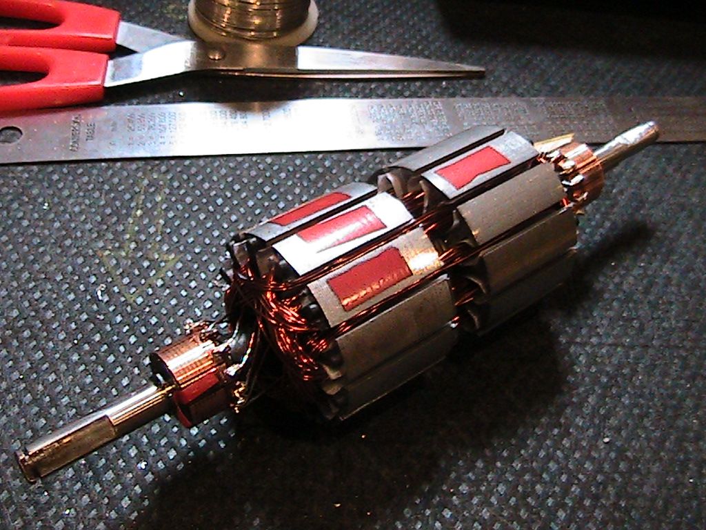
              We have learned many WRONG Concepts for so many years...that add more than a Century...for example expressing that : "A Motor is a Generator...as well as a Generator could be used as a motor..." WRONG!!!

              A Motor IS a Motor...and a Generator IS just a Generator...this wrong concepts have created -over so many years- a FIRM visualization of what a Generator MUST look like from a DEAD END point of view.

              If We look at Tesla's Patents...we will see other types of Generators* Concepts...different structures...different kind of magnetic interactions, different winding configurations...therefore, different type of results from whatever we all have up to now, which is "conveniently" very "toxic" generators that only a "Herculean" Gas or Diesel Engine could turn...in other words...so far in our History...to run a Generator is similar to watching a Zumo Fight or a Heavy Weight Wrestling Fight...

              Pathetic...

              Anyways, sorry about deviating from your future projects...I guarantee that Scooter is gonna blow out any "original" ones...


              Regards


              Ufopolitics
              Last edited by Ufopolitics; 10-07-2014, 01:23 PM.
              Principles for the Development of a Complete Mind: Study the science of art. Study the art of science. Develop your senses- especially learn how to see. Realize that everything connects to everything else.― Leonardo da Vinci

              Comment


              • Originally posted by HuntingRoss View Post
                UFO recommends 'hedges' to close the slots.

                I have found these two options -

                Slot closures

                Enamelled Copper Wire,Motor Repair

                Slot wedges

                Enamelled Copper Wire,Motor Repair

                The first one describes what I want to do...the second one sounds like 'hedges'.

                The closures look like an OK price considering I'm getting 99m of stuff I'll never use and the wedges are way expensive.

                Helpful hints welcome

                mark
                Hello Mark,

                The second link , the "U" Shape "Wedges" are the ones we use...(sorry, I always spell it wrong as Hedges)

                I have cut them to use them in smaller applications. but I mainly bought it for Imperial winding:

                [IMG][/IMG]

                Regards


                Ufopolitics
                Principles for the Development of a Complete Mind: Study the science of art. Study the art of science. Develop your senses- especially learn how to see. Realize that everything connects to everything else.― Leonardo da Vinci

                Comment


                • Floss Before You Brush.

                  Originally posted by HuntingRoss View Post
                  UFO recommends 'hedges' to close the slots.

                  I have found these two options -

                  Slot closures

                  Enamelled Copper Wire,Motor Repair

                  Slot wedges

                  Enamelled Copper Wire,Motor Repair

                  The first one describes what I want to do...the second one sounds like 'hedges'.

                  The closures look like an OK price considering I'm getting 99m of stuff I'll never use and the wedges are way expensive.

                  Helpful hints welcome

                  mark
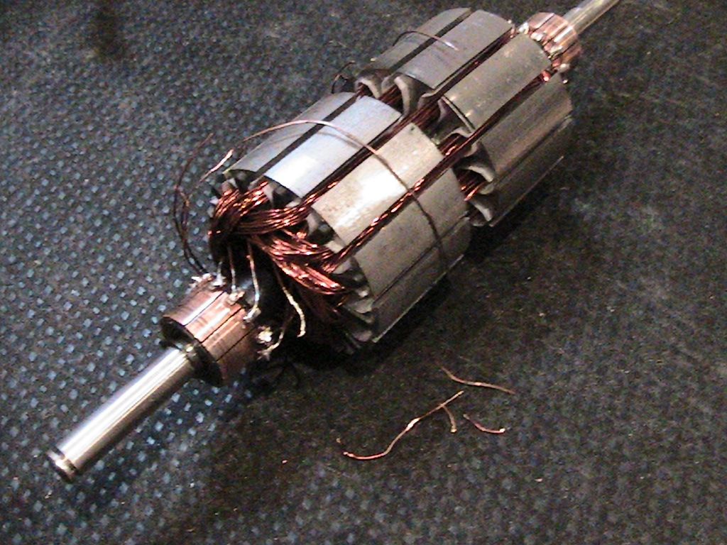
                  Hi Mark, I'll let you and the others possibly have a little laugh at me. The attached photo is a RS armature. Notice the crisscross white string like tie holding the windings down tight. Ha ha it's dental floss which is very strong and has a coating that makes it sort of stick together. You can also put a dot of super glue on any knots. There is actual tie material you can buy from electrical supply outlets but in a pinch this has worked well for me on small motors. Now the safety feature is if you run the motor and start to smell peppermint then you know your motor is starting to get to hot. LOL.
                  Have fun.
                  John
                  Attached Files

                  Comment


                  • My kinda guy

                    John. Dental floss is aiming more where I want to go. Paying big for 100m of something I'm not going to use that much doesn't appeal to me.

                    I will swathe in dental floss...as much as it takes...unless I can find a friendly motor repair shop that will sell small quantities.

                    Good tip.

                    UFO. Your new thing waiting in the wings sounds intriguing. I spent time a few years back reading Tesla patents and always felt I was on the edge of discovering the hidden secrets. There's a fine line between being liberated by having a small (but sufficient) amount of knowledge and being indoctrinated into a mindset. I read some very interesting articles by Don Hotson on Dirac's equations and knew there had to be more than we settle for. At work over the past week I have turned the usual Youtube scepticism on its head. These people who spend their lives doubting but never doing have met for the first time someone who has done it and proved it works. The credit is with you, but alas they find themselves having to doubt a doctrine they have been bred to follow...including a member of the IEE.

                    When you start your new thread, please post a link here so I don't miss it. At present I am focusing on this thread only.

                    Dana. Thanks for the imperial links. It looks like I will be waiting for the new revelation before I purchase, which gives me time to rebuild and install my 'beast' into the Pink scooter

                    http://www.amazon.co.uk/Electric-Sco...s=120w+scooter

                    Best regards to all

                    mark

                    Comment


                    • Originally posted by HuntingRoss View Post
                      John. Dental floss is aiming more where I want to go. Paying big for 100m of something I'm not going to use that much doesn't appeal to me.

                      I will swathe in dental floss...as much as it takes...unless I can find a friendly motor repair shop that will sell small quantities.

                      Good tip.

                      UFO. Your new thing waiting in the wings sounds intriguing. I spent time a few years back reading Tesla patents and always felt I was on the edge of discovering the hidden secrets. There's a fine line between being liberated by having a small (but sufficient) amount of knowledge and being indoctrinated into a mindset. I read some very interesting articles by Don Hotson on Dirac's equations and knew there had to be more than we settle for. At work over the past week I have turned the usual Youtube scepticism on its head. These people who spend their lives doubting but never doing have met for the first time someone who has done it and proved it works. The credit is with you, but alas they find themselves having to doubt a doctrine they have been bred to follow...including a member of the IEE.

                      When you start your new thread, please post a link here so I don't miss it. At present I am focusing on this thread only.

                      Dana. Thanks for the imperial links. It looks like I will be waiting for the new revelation before I purchase, which gives me time to rebuild and install my 'beast' into the Pink scooter

                      Electric Scooter - Lextek 120w (Pink): Amazon.co.uk: Car & Motorbike

                      Best regards to all

                      mark
                      Hello Mark, thanks for answering. Remember i never used the floss on anything real important. Maybe someone will still say it shouldn't be done. I like the scooter but I hope you're not my size. hehe. Mark remember if you have a motor ready for a scooter you should be able to determine if it's better than the original equipment without spending money on a scooter. On the other hand if you choose the scooter for the proof and it works you will be offering up the kind of test people are waiting for. So simple and reliable, Which one goes farther and by how much. Don't even need a single meter to have proof.
                      Good luck
                      John l

                      Comment


                      • Tabs

                        Well I did some 'not nice things' to get the tabs up...involving a chisel...a little bit of comm repair required...why do THEY make it so difficult.

                        John. You're exactly right. My motor works better at 5v already, just another 19v to go....One shouldn't judge an outcome before it's done...BUT...that never spoilt a good hypothesis before. My thoughts are - If this scooter does 20km/h with a motor rated at 24v 2500rpm and the rebuild is doing 3000rpm at 5v with more torque. Then all things being equal one would never have cause to open the throttle past 5v and still come out on top.

                        So at the end of this little experiment, my daughter scores a hot scooter in pink and the doubters can find a new subject to proclaim.

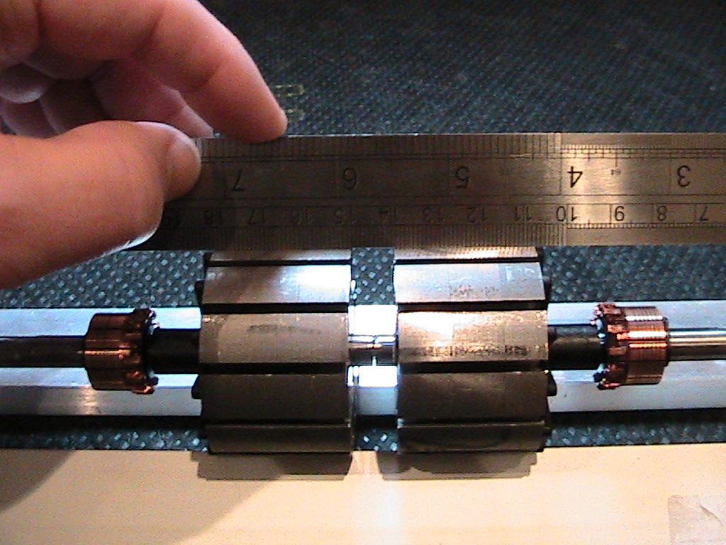
                        On the subject of keeping the wires in the slots. Check the gap in the middle of my rotor...

                        [IMG][/IMG]

                        The consequence of my build is a convenient gap in the middle to tie off the wires and 'save me some shekels'...dental floss has it unless there is an unforseen problem.

                        I'll still be trying to find a helpful repair store though...that also sounds priceless.

                        mark
                        Last edited by HuntingRoss; 10-08-2014, 06:40 PM.

                        Comment


                        • Originally posted by HuntingRoss View Post
                          Well I did some 'not nice things' to get the tabs up...involving a chisel...a little bit of comm repair required...why do THEY make it so difficult.

                          John. You're exactly right. My motor works better at 5v already, just another 19v to go....One shouldn't judge an outcome before it's done...BUT...that never spoilt a good hypothesis before. My thoughts are - If this scooter does 20km/h with a motor rated at 24v 2500 rpm and the rebuild is doing 3000rpm at 5v with more torque. Then all things being equal one would never have cause to open the throttle past 5v and still come out on top.

                          So at the end of this little experiment, my daughter scores a hot scooter in pink and the doubters can find a new subject to proclaim.

                          On the subject of keeping the wires in the slots. Check the gap in the middle of my rotor...

                          IMG_2740.jpg Photo by huntingross | Photobucket

                          The consequence of my build is a convenient gap in the middle to tie off the wires and 'save me some shekels'...dental floss has it unless there is an unforseen problem.

                          I'll still be trying to find a helpful repair store though...that also sounds priceless.

                          mark
                          Hello Mark, I'm sorry to say I don't share the confidence you have with your hypothesis but I don't want to discourage you with anything more than that. You will have the scooter very soon and as usual I hope I'm wrong about the typical high current and rpm's of these motors and how they will work in real life applications. Richie asked me to hang around for suggesting test methods so let me make a few comments that might pertain or might not. If you have a scooter and you know the cruise speed range, you could use the circumference of the wheel to figure out just about how many rpm's the motor will be operating at while cruising right? Now we all know that motors in general have an rpm range where the motor is at it's highest efficiency. Does the high rpm of these windings lend itself to be the most efficient option for your scooter? Does the all north motor need to have this high speed? Would the motor operate better with longer windings bringing the the voltage requirements closer to the 24 volts of the system? Doesn't an electric motor run more efficient if you can use more voltage to run it? I've mentioned this before but this is a simple idea of a test in my opinion. I take a scooter motor and put a radiator fan on it. I might even be lucky and while it was running get the same rpm as what it would be cruising down the road. So let's say your going around 1,200 rpm's at what ever voltage you are using. I now take a current reading to see how many amps I draw with the stock motor while cruising. A voltage times current can give me watts and watts can be converted to horsepower if desirable right? Ok time for the converted motor. Match the rpm of the test with the oem motor by adjusting the input voltage. Oh wait you won't need as much voltage, hmm but you might need more than you think, you never know. Simply take the voltage no matter what it is when you reach the right rpm and multiply it by the current draw to see what the wattage is. If it's less than the first reading with the oem motor then you really have something going for yourself. Wait, that's right, the asymmetric motor could be charging the battery as you test, very possible but you would be checking how long both motors run before the battery drops to it's safe depleted value. You might even check the time it takes for each motor to slow to a certain rpm. Some people like to use generators and I do too.You can use another brushed DC motor for this as well. Think about this. You can connect your asymmetric motor to a generator and use the generator as a semi-precision load bank. You could put bulbs or resistance or even a short on the generator to present different loads to the shaft of the test motor. You can make all kinds of test measurements with a setup like this. Basically a simple test is to put a load on the generator and see what wattage is required for each of the test motors to get the same rpm on the generator. Another valuable test device is a dynamometer also. There was a lot of talk about this earlier but it seems as though it wasn't pursued by many. If you missed the post you can see my version of the device here:

                          https://www.youtube.com/watch?v=u9vh...3lTJIrHm5FLLPA

                          Well I'm not sure if anyone bothered to make it this far but I'm open for corrections if my thinking is off.
                          Mark you better not take that scooter apart and not get it back together for your little darling. LOL. I'll suggest a collection to replace it if you do.
                          Good Luck.
                          John

                          Comment


                          • Scooter Conversion to Asymmetrical Power Train...VERY IMPORTANT!

                            Originally posted by HuntingRoss View Post
                            Well I did some 'not nice things' to get the tabs up...involving a chisel...a little bit of comm repair required...why do THEY make it so difficult.

                            John. You're exactly right. My motor works better at 5v already, just another 19v to go....One shouldn't judge an outcome before it's done...BUT...that never spoil a good hypothesis before. My thoughts are - If this scooter does 20km/h with a motor rated at 24v 2500rpm and the rebuild is doing 3000rpm at 5v with more torque. Then all things being equal one would never have cause to open the throttle past 5v and still come out on top.

                            So at the end of this little experiment, my daughter scores a hot scooter in pink and the doubters can find a new subject to proclaim.

                            On the subject of keeping the wires in the slots. Check the gap in the middle of my rotor...

                            [IMG][/IMG]

                            The consequence of my build is a convenient gap in the middle to tie off the wires and 'save me some shekels'...dental floss has it unless there is an unforseen problem.

                            I'll still be trying to find a helpful repair store though...that also sounds priceless.

                            mark
                            Hello Mark,

                            One thing related to Photobucket...

                            You could add your pictures in your post here like I did above to your quoted post, by copying the IMG link on your Photobucket site right side bar at SHARE LINKS and pasting it when you choose the small yellow square icon (representing a picture) here on your Editor...This way anyone could see images, even if they are not logged in.

                            Now back to your Asymmetrical Scooter Motor,

                            I know it makes sense from your point of view when comparing voltage/speed of both machines...but, one main thing you must realize is that you have re-used the existing old wire from your Symmetric Motor, and that is NOT enough wire for an Asymmetric Motor.

                            The way Symmetry works related to its windings...is that ALL Coils are connected in series, therefore, from (+) Pos. Brush to (-) Neg. Brush of the Original Motor you will get around Six Coils in series connected in parallel to the other Six in series (on your 12 pole, 12 Coils Symmetrical)...That is NOT the way Asymmetrical works, since from (+) Pos. Brush to (-) Neg. Brush on your Asymm. Motor you will get the resistance of JUST ONE PAIR of COILS, or in your case the NN Type you get just THREE COILS IN SERIES per Momentum of Input. The result is a MUCH LOWER resistance at Input Brushes for Asymmetrical Motors.

                            Note*: We are disregarding the fact that every interval of time we get Two Commutator Elements contacting Brushes, since this way it would add around same value (G1+G2/2= G#) since all Groups are supposed to be identical number of turns/resistance.

                            One thing that I have recommended to all Members here replicating in order to compare Original versus Asymmetric, is to FIRST take a resistance measurement from the original motor directly from 180º apart commutator elements, and here we must apply the formula for number of series coils then in parallel to come up with Total Resistance per Input....Then We MUST match that value Per each Coil in our Asymmetric Motor...for example in your case:

                            Your Symmetric Motor is a 12 Coils in series, but when we input brushes at center of Six/Six in Parallel, then we have:

                            Coil1+Coil2+Coil3+Coil4+Coil5+Coil6 divided by Coil7+Coil8+Coil9+Coil10+Coil11+Coil12 =Total Resistance (at Input Brushes)

                            In your Asymmetric Motor You have chosen the All North Groups, therefore, you will have Three (3) Coils in series in the Total "Momentum" at Input...so you Must match the resistance value at those Three Coils in series to the Original Symmetric Total Resistance.

                            That is why I suggested to go a bit finer wire...in order to gain higher resistance with lesser turns (therefore, less space) than Original wire.

                            Another simple way to take your Symmetric total SERIES resistance is to disconnect JUST ONE of your wires (typically I do it from the closing commutator element where you could see two wire ends pressed at element)...then from that loose wire and the other end (opening the tie) you will have the Total SERIES adding of all Coils...so you just have to divide by Two (2) to obtain a pretty accurate measurement of the resistance at brushes.

                            This is VERY Important to be done before anything!!

                            Having very close resistance values at Input of your Asymmetric Motor, matching the Original Motor, will guarantee the Scooter Controller will not blow any MOSFET's switching transistors. and I don't know if you know...but when this occurs the Scooter will go full blast speed not obeying controller accelerator knob any more (Runaway Scooter) and that is VERY Dangerous!!...I do NOT want any kind of accidents to happen to your little princess!!


                            So, some other precautions you should take:

                            1- Instal a very handy KILL Switch from the POSITIVE terminal of Batteries, not the Negative...MOSFET's are typically N-Channels so it may not do it if you are trying to cut off from the wrong negative point. Switch MUST be easy access while driving.

                            2- Make FIRST, (before going on the road) lots of bench testing with power wheel lifted SECURE and adding some big mechanical load to the Tire while accelerating, or you could play with brakes on (not all the way) and accelerating simultaneously...then checking Controller Temperature at Heat Sink section, or better, take controller apart and read FET's temperature directly.

                            3- Also check Temperature of the Batteries and cables attached to them while testing (hopefully they would be typical low Amp/Hour Lead Acid type)

                            Even the All North is a very smooth driving motor...(does not arc/spark commutators or gets radical short circuits, while running very cool)...it is very smart to take all kind of precautions...since you could see the speed and torque this machines could develop...so be very careful when driving on the road.

                            About the Output...

                            Typically your Asymmetric Motor Output could be connected -through a switch- to the Batteries with at least ONE DIODE rated for that Voltage and Amperage to prevent feeding back to Output (One way only to Batteries, not allowing reverse flow).

                            Another fancy and more expensive way to handle Output or Returned Energy, would be to add between Batteries and Output another Bank of Super Capacitors that match the same operating voltage, still using one way Diodes.

                            However, for initial and loading bench running testings You should keep output disconnected, or switch turned off...normally this return switch should be turned on when cruising at steady speed and not during sudden full throttle accelerations, unless you have the Supercaps Bank installed that would absorb sudden charging spikes.

                            Any questions please feel free to ask me or Dana about this issues.


                            Kind Regards


                            Ufopolitics
                            Last edited by Ufopolitics; 10-08-2014, 11:50 AM.
                            Principles for the Development of a Complete Mind: Study the science of art. Study the art of science. Develop your senses- especially learn how to see. Realize that everything connects to everything else.― Leonardo da Vinci

                            Comment


                            • Daunting

                              Thanks John. I completely get where you're coming from...which is why I want to go empirical rather hypothical...(I think I just made that word up to rhyme...hypothetical was what I was thinking of but I prefer my new word)

                              Thanks UFO. I suddenly feel like I'm at a bottom of a steep learning curve. I need to read your post lots and lots to digest that information. The bits I immediately understood though was 'dead daughter' and 'melted Christmas present'

                              I'm not sure how I approximate the resistance of the original motor now to try and balance the new one...Hmm. Looks like in my rush to do this I missed a few important steps. And the original motors are out of stock now with no re-stock date...The 3 new coils (one group) used almost to the inch the same amount of wire as the original single coil...could I just measure that and multiply by 6 ?

                              Another option. I could remove the electronic control system and replace with rheostat...it's not efficient but it wont melt down either...unless of course it does. This way I could trade efficiencies with ability to obtain data.

                              On the subject, to my surprise the scooter arrived today, less than 24 hours from order...fast !! Maybe they already have a nifty motor installed. Obviously I have tried it out in the living room. I then read the instructions and it said don't use indoors...Something tells me I don't conform.

                              My magnet wire is on order so I'll get on and re-wind just as soon as I can and pack as much in as possible to try and get the resistance up.

                              And finally. I tried to change my links...some worked, some didn't. So hopefully here are the ones that didn't -

                              [IMG][/IMG]

                              [IMG][/IMG]

                              [IMG][/IMG]

                              [IMG][/IMG]

                              [IMG][/IMG]

                              Huge thanks and best regards

                              mark
                              Last edited by HuntingRoss; 10-08-2014, 07:21 PM.

                              Comment


                              • @UFO & Team,

                                Questions

                                *Please use Marks diagram image above for reference*

                                Parameter: Setting the "Timing" of coil one(C1) of group one(G1) at TDC of the bi-sector of the magnetic or as close as possible after the mag bi-sector. Plus, winding one more pole.

                                Will this increase the Amps?
                                If so, Is the extra torque worth the extra amps?
                                Do the RPMs increase?


                                Keep it Clean and Green

                                Midaz

                                P.S. Mark, welcome aboard!

                                Comment

                                Working...
                                X