Announcement

Collapse
No announcement yet.

My Asymmetric Electrodynamic Machines

Collapse
X
 
  • Filter
  • Time
  • Show
Clear All
new posts

  • Originally posted by Midaztouch
    Steve

    Your an easy target but I'm deleting all of my post.

    My team has work to do!


    UFO,

    I don't won't Erfender around anymore. Is that ok with you?

    Midaz
    Richard,

    I'm cool with that....erase your garbage and I will do the same and that will be the end of it.


    added...

    Since you opened this last post of yours as a threat, I take that as a sign that this isn't over.....I'm prepared....come when you're ready!
    Last edited by erfinder; 07-21-2014, 11:42 AM.

    Comment


    • My Apologies

      Originally posted by DadHav View Post
      With a smile on my face: UFO, you and I are probably the most diametrically opposed people on the face of earth when it comes to thought processes and the way things should be tested. That will always get in between us. That doesn't mean I have any dislikes towards you or disbelieve in your cause. I may have beat around the bush to much about the whole topic I was invited into. I just plain disagree with the flash test as you call it as it would pertain to the claim of over unity. I just tried to show a flash comparison using a battery and capacitors. My test results, as you had in your final measurements, where very similar. I would certainly imagine if I used one of my stator motors with generator coils I could have made a very impressive similar video but that's all there is to it, you and I and everyone else knows all these conversations can be flushed right down the drain when a real life, real user friendly practical application is demonstrated. I hope Kogs drives across the continent puts a propellor on Nesse and runs up on the Florida cost line to say hello. I mean it Kogs, Dana, Richie and everyone else. I would like to see this work, so don't get me wrong on that. I've just been adverse to testing techniques and quick claims from the beginning. That makes me so different that I need to keep my distance and come around only once in a while to disrupt things. LOL.
      John
      PS Have to go now and make sure the confetti in the plane isn't sticking together. It will need to be nice and fluffy for the celebration flight.
      Hello John,Hello to All,

      Basically this post is an apology on my end...I was dead wrong, and I am admitting it here...

      @DadHav: I did exactly the same Test You did, John...with my own set up, except there was no Motor hooked, and You are COMPLETELY RIGHT, Supercaps get a charge when I set them on Parallel, then the whole thing repeats as well as it did with Motor connected in Series all Caps...it shows OVERUNITY, BUT IN MUCH LESS TIME that it took with Motor on...

      Sorry for being so stubborn!...but at the same time, Many Thanks for doing that test for Us.

      We learn from our mistakes...it is part of Experimenting over and over...as it is the great deal of Open Sourcing our research out here.

      The Circuit, even as independent Banks 1 & 2 on this Connection, still have Parallel connection between their Batteries and Caps on each side...

      So let's call this whole Video and Test as VOID, NULL...not good and a tendency to give WRONG READINGS from Motor.

      When We move into the All North Groups and Four Gate Machines, then We will repeat same Test, but this time Batteries and Supercaps would be in completely isolated circuits from each others...so the conclusions, either great or terribly bad...still will get Us to think if or not we are on the right track

      Thanks again John!

      I will come back soon and please, I know has been quite long, so make sure the Confetti keeps being fluffy...


      Regards to All


      Ufopolitics
      Principles for the Development of a Complete Mind: Study the science of art. Study the art of science. Develop your senses- especially learn how to see. Realize that everything connects to everything else.― Leonardo da Vinci

      Comment


      • Originally posted by Ufopolitics View Post
        Hello John,Hello to All,

        Basically this post is an apology on my end...I was dead wrong, and I am admitting it here...

        @DadHav: I did exactly the same Test You did, John...with my own set up, except there was no Motor hooked, and You are COMPLETELY RIGHT, Supercaps get a charge when I set them on Parallel, then the whole thing repeats as well as it did with Motor connected in Series all Caps...it shows OVERUNITY, BUT IN MUCH LESS TIME that it took with Motor on...

        Sorry for being so stubborn!...but at the same time, Many Thanks for doing that test for Us.

        We learn from our mistakes...it is part of Experimenting over and over...as it is the great deal of Open Sourcing our research out here.

        The Circuit, even as independent Banks 1 & 2 on this Connection, still have Parallel connection between their Batteries and Caps on each side...

        So let's call this whole Video and Test as VOID, NULL...not good and a tendency to give WRONG READINGS from Motor.

        When We move into the All North Groups and Four Gate Machines, then We will repeat same Test, but this time Batteries and Supercaps would be in completely isolated circuits from each others...so the conclusions, either great or terribly bad...still will get Us to think if or not we are on the right track

        Thanks again John!

        I will come back soon and please, I know has been quite long, so make sure the Confetti keeps being fluffy...


        Regards to All


        Ufopolitics
        WELL, let me be the first to congratulate myself! Ha, thats the first time I used one of those little things here. You know I'm just kidding UFO. I appreciate your candor very much and feel good that we actually had a meaningful conversation. All here are inventors and all should feel obligated to search for avenues that lead in the right direction. If something seems to be off course it should be talked about right? A lot of time and sometimes embarrassment can be saved by catching things before they go to far. It was a pleasure to be some help. I feel so good I might do a practice confetti drop on my simulator.
        I have a good friend in Portugal named Eduardo. Ed just told me something very nice regarding some personal setbacks of my own and I loved the quote:
        "You certainly can't control the direction of the wind, but you can adjust and trim your sails" I hope soon you guys will make the right adjustments and have some smooth sailing.
        Kindest Regards
        John H.

        Comment


        • Originally posted by DadHav View Post
          WELL, let me be the first to congratulate myself! Ha, thats the first time I used one of those little things here. You know I'm just kidding UFO. I appreciate your candor very much and feel good that we actually had a meaningful conversation. All here are inventors and all should feel obligated to search for avenues that lead in the right direction. If something seems to be off course it should be talked about right? A lot of time and sometimes embarrassment can be saved by catching things before they go to far. It was a pleasure to be some help. I feel so good I might do a practice confetti drop on my simulator.
          I have a good friend in Portugal named Eduardo. Ed just told me something very nice regarding some personal setbacks of my own and I loved the quote:
          "You certainly can't control the direction of the wind, but you can adjust and trim your sails" I hope soon you guys will make the right adjustments and have some smooth sailing.
          Kindest Regards
          John H.
          That's why Dadhav is necessary.

          for your input and showing how to critique someone's work properly

          Well gentlemen, let the fun begin with the 4 stators!

          Keep it Clean and Green
          Midaz
          Last edited by Midaztouch; 07-23-2014, 12:48 AM.

          Comment


          • UFO, looking at building an new rotor for quad stator GM window motor

            Here is the post when I last brought it up.

            Originally posted by sampojo Post #6586 View Post
            Hi Ufo

            I am thinking about making a new rotor. I like my QP10 quad motor for power generation capability, since the motor body is wall-to-wall covered with magnets in a quad stator layout. It has a construction weakness in that I used solder on the external wiring connection, that I believe I can replace with crimps. At 26ga it ran a little hot at 130defF coming out along the endplates., .6-.7ohm coil pair wQP10 winding pattern.

            I like my doublerotor dual stator alot since it ran cooler, twice the wire then of course and ohms prbly at about 1.1 per group, apparently less powerful too!. I don't like the shorter magnets now either.

            You asked me a question back on pg 219 P6566, here is the discussion:


            When you asked if I could put the G10 rotor in the body of my QP10 you seemed to imply that the dual stator group winding might work in the Qaud stator design. Maybe not huh? But what about the P10 unipolar which I would like to investigate. Sure I can do the P10 double rotor for a dual stator and we know it should work well, but I like the wall-to-wall magnets in the QP10 motor body. I guess 26ga is still optimum there, since I should be able to recoup heating as a problem by using pulsers, which I am starting a more agressive assembly campaign on those. But I think you have alluded to differences in quad stator designs. And overall I want to test the Pairs unipolar design. I think the 44000 rpms you got on the RS 5-poles unipolar pair design is the effect I want to work with most.

            Question: Do I need a redesign of the P10 unipolar dual stator design for a Quad Stator motor?

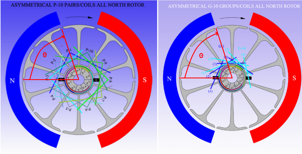
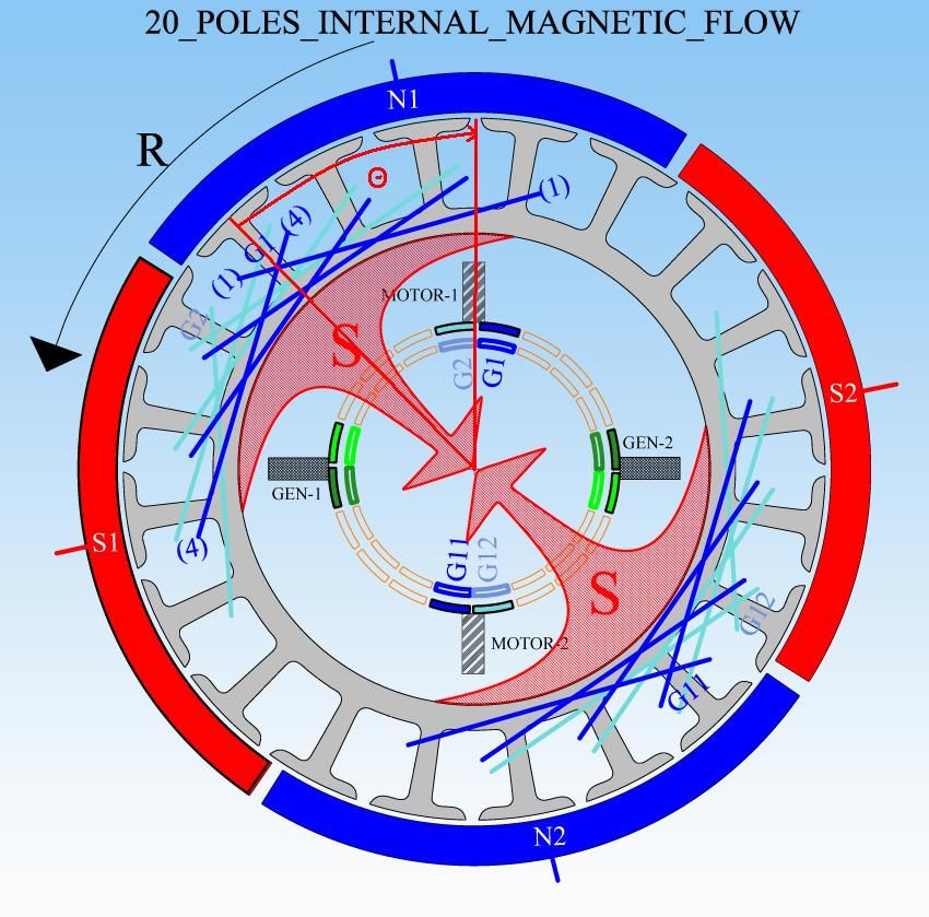
            Looks like answer is no if I compare the timing angles, group vs pair unipolar looks constant. But the 20 Pole Quad stator Bosch diagram timing angle looks a little larger at 4 1/2 poles vs. a translated 4 poles (Theta in the diagrams)
            10-pole Group vs Pair design have same theta


            Looking at coil G1 firing here, 20 pole quad stator has similar Theta, maybe a little smaller by 1 1/2 pole arc?


            So It looks like rotors would not be interchangeable in unipolar motors between quad and dual stator designs to me since the theta's are very different, and one leading and one lagging the motor brush.

            So a Pair unipolar 10-pole design for a quad stator would use the same timing angle used by the Quad stator 20-Pole apparently, and the sub-coils would subtend 2-poles?

            Thanks, Ufo
            So of I do the math myself here, the timing angle you used on your bosch 20-pole is 2.5 poles or 45 deg.

            If it is right to use the same angle for the 10 pole that would be about 1.25 poles in an angular measurement.

            Ufo, Is this right?

            Then just use the same unipolar winding diagram as the dual stator 10-pole?

            thanks,

            Joe recovering from hip surgery, or where did that horse come from that kicked me in the hip? Almost better now...
            Up, Up and Away

            Comment


            • G10_Quad Stators

              Originally posted by sampojo View Post
              Here is the post when I last brought it up.


              So of I do the math myself here, the timing angle you used on your bosch 20-pole is 2.5 poles or 45 deg.

              If it is right to use the same angle for the 10 pole that would be about 1.25 poles in an angular measurement.

              Ufo, Is this right?

              Then just use the same unipolar winding diagram as the dual stator 10-pole?

              thanks,

              Joe recovering from hip surgery, or where did that horse come from that kicked me in the hip? Almost better now...
              Hello Joe,

              Hope You get back to absolutely normal recuperation very soon...

              Ok, kind of hard to see what exactly you mean by Theta Angle...normally, whenever we use angles in the All North Types, they are either from Bisector to Bisector or the angle enclosed by the whole Group-Pair...or enclosed by each Coil.

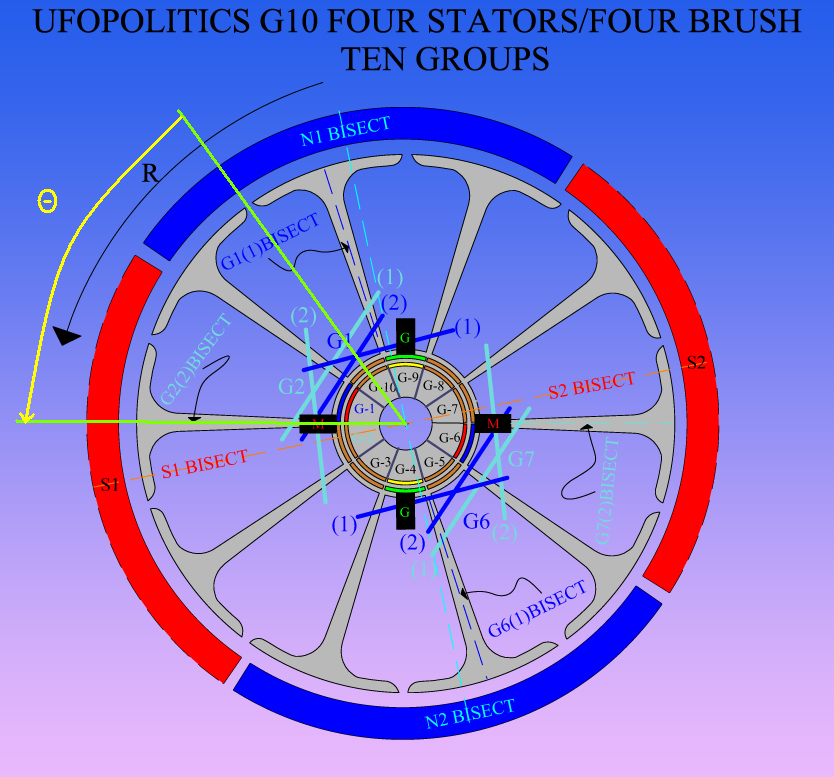
              You are asking for a Ten Pole in a Four Stator/Four Brush Housing...and Nope, unfortunately it will not work the same as the P10 Two Stator Rotor, nor the same as in the G-10 Two Stators, in the All North Type...some modification must take place here...take a look below:

              [IMG][/IMG]

              Even though We are using Two Coils per Group and we could call them "Pairs"...We have the same approach as the RS Five Poles...because of the overlapping between Two Coils.

              I tried with Three Coils in each Group...nope can't do it...why?

              Because in a Four Stators we are limiting (shortening) the Angles of Interactions between N-S ...never the same as in a Two Stator. Yeah, in the 4S We have Interact Angles of 90º between N-S Stators Bisectors.

              Let´s take a look above Diagram...and read below...

              G1(Dark Blue) Coil One (1) wraps around Three Poles, so Center Pole center would be its Bisector, and I show it as G1(1)BISECT.
              Notice Brush M on left is just starting to make contact according to Rotation "R" with G1 (Blue) Commutator Element...good so far?...great.
              Now, like I have said before in ALL North Groups, We MUST LOOK at the "Leaving Group" for a perfect alignment, in this case it is G2 in Light Blue...So then in that Group We must specifically look at the LAST COIL BISECTOR G2(2)BISECT... AND...MAKING SURE it is not Aligned/Nor Passed South Stator Bisector (S1).

              And in real builds, we must make sure when it's still in contact with brush (meaning being energized) it still do not aligns with South Stator Bisector...until it is completely disconnected.

              So, what I always do here...is to Fire the coming Coils (G1) First Coil (1) Bisector...AS CLOSE AS POSSIBLE TO North Stator Bisector (Repulse Stage)..leaving Us a good space at G2 (2) Bisector which is at Attract mode.

              The same exact deal takes place at 180º with G6-G7...

              The same way I have recommended before...doing G1-G2, then doing G6-G7...and so on, in order to balance Copper at 180º.

              Any doubts let me know...


              Regards


              Ufopolitics
              Last edited by Ufopolitics; 07-22-2014, 02:40 PM.
              Principles for the Development of a Complete Mind: Study the science of art. Study the art of science. Develop your senses- especially learn how to see. Realize that everything connects to everything else.― Leonardo da Vinci

              Comment


              • About Imperial All North Rotor Only...

                Hello Guys,

                I have been talking to Dyann Derosa at Imperial Electric about putting up together for all of Us here a special price on JUST A ROTOR KIT for the P56 Imperial, which is EXACTLY One(1) Rotor with Shaft On, and Two (2) Commutators...That was about a few days ago, and I just got the email from her...

                Rotor w/Shaft (Part# 0510052): 35.00 USD each
                Commutators (Part# 0567028C):24.00 USD each X2=48.00

                ROTOR KIT: 83.00 USD

                Those are great news!!...but, the bad news is that there is a delay of Six Weeks (she said maybe sooner)...because of Commutators Supply.

                I thought for all of Us, owners of an Imperial already put together, Housing, mainly with Brush Caps aligned, Magnets etc,etc...it would be a great deal to own one of this Rotor Kits...since we could exchange in the same Housing to run different tests with different windings...basically comparing N-S Pairs versus N-N Pairs and All North Groups...


                Regards to All


                Ufopolitics
                Principles for the Development of a Complete Mind: Study the science of art. Study the art of science. Develop your senses- especially learn how to see. Realize that everything connects to everything else.― Leonardo da Vinci

                Comment


                • will you be sending your new winding motor/generator units to IMPERIAL for testing? especially for torque testing

                  Comment


                  • Torque...is the least of my worries...

                    Originally posted by esesenergy View Post
                    will you be sending your new winding motor/generator units to IMPERIAL for testing? especially for torque testing
                    Nope, I will not be sending my new winding-motors...

                    I will be taking them myself.

                    The Torque is the least of the worries, esesenergy...none of my machines have a "Torque Problem" as you have said prior.

                    But it is understood since you have not done any of them...so you don't know.

                    Ufopolitics
                    Principles for the Development of a Complete Mind: Study the science of art. Study the art of science. Develop your senses- especially learn how to see. Realize that everything connects to everything else.― Leonardo da Vinci

                    Comment


                    • Hello UFO

                      I am waiting for two rotor sets at present and have talked to several others that are also. At least now we know how long to wait as before we got not answer when we asked Dyann how long it would be.

                      Dana
                      "Today's scientist have substituted mathematics for experiments and they wander off through equation after equation and eventually build a structure which has no relation to reality."
                      Nikola Tesla

                      Comment


                      • Hi UFO and all, just a quick update with where I am up to.

                        Have just finished planting the years Garlic crop, the rows are 100mt long and I have planted 28 rows this season, enclosed pic's.

                        All the rows are heavily mulched with material harvested, on farm, with my forage harvester, and placed by hand, the seed is also hand planted.

                        We are in drought here, luckily I have an endless water supply from an underground bore, and can run a small irrigator 24/7 if needed.
                        Only trouble is the energy cost to run it,( about $30.00 / night AUD.)

                        Have just planted yesterday my Wheat crop, on the back of 8mm or rain, it's very late, almost outside the planting window, so fingers crossed.

                        Now it's just a matter of a bit of catch up work and hopefully I will have some time to wind my all north MAG3 rotor.

                        Cheers Everyone, Cornboy.

                        [IMG][/IMG]

                        [IMG][/IMG]

                        Comment


                        • timing angle 10 poles quad stator design

                          Originally posted by Ufopolitics View Post
                          Hello Joe,

                          Hope You get back to absolutely normal recuperation very soon...

                          Ok, kind of hard to see what exactly you mean by Theta Angle...normally, whenever we use angles in the All North Types, they are either from Bisector to Bisector or the angle enclosed by the whole Group-Pair...or enclosed by each Coil.

                          You are asking for a Ten Pole in a Four Stator/Four Brush Housing...and Nope, unfortunately it will not work the same as the P10 Two Stator Rotor, nor the same as in the G-10 Two Stators, in the All North Type...some modification must take place here...take a look below:

                          [IMG][/IMG]

                          Even though We are using Two Coils per Group and we could call them "Pairs"...We have the same approach as the RS Five Poles...because of the overlapping between Two Coils.

                          I tried with Three Coils in each Group...nope can't do it...why?

                          Because in a Four Stators we are limiting (shortening) the Angles of Interactions between N-S ...never the same as in a Two Stator. Yeah, in the 4S We have Interact Angles of 90º between N-S Stators Bisectors.

                          Let´s take a look above Diagram...and read below...

                          G1(Dark Blue) Coil One (1) wraps around Three Poles, so Center Pole center would be its Bisector, and I show it as G1(1)BISECT.
                          Notice Brush M on left is just starting to make contact according to Rotation "R" with G1 (Blue) Commutator Element...good so far?...great.
                          Now, like I have said before in ALL North Groups, We MUST LOOK at the "Leaving Group" for a perfect alignment, in this case it is G2 in Light Blue...So then in that Group We must specifically look at the LAST COIL BISECTOR G2(2)BISECT... AND...MAKING SURE it is not Aligned/Nor Passed South Stator Bisector (S1).

                          And in real builds, we must make sure when it's still in contact with brush (meaning being energized) it still do not aligns with South Stator Bisector...until it is completely disconnected.

                          So, what I always do here...is to Fire the coming Coils (G1) First Coil (1) Bisector...AS CLOSE AS POSSIBLE TO North Stator Bisector (Repulse Stage)..leaving Us a good space at G2 (2) Bisector which is at Attract mode.

                          The same exact deal takes place at 180º with G6-G7...

                          The same way I have recommended before...doing G1-G2, then doing G6-G7...and so on, in order to balance Copper at 180º.

                          Any doubts let me know...


                          Regards


                          Ufopolitics
                          To understand the firing sequences in your diagrams, I started drawing lines between the energizing motor brush set and the centerline of the matching coil set. I was trying to apply the nearest unipolar design of a quad stator, your last bosch rendering. It has the equivalent "2.5 poles angular measurement" for this definition. Translating to a 10-pole rotore would be 1.25 poles.

                          Very helpful how you make clear the changes in geometry for a 10-pole changes everything. I have showed your diagram re-interpreted with my theta timing angle. To me this is the definitive parameter in wiring your diagrams and helps me see things better. So here it is if it helps anyone else.
                          Theta angle subtended by green angle

                          While I tried to reverse engineer the 20-pole bosch diagram erroneously, you show the angle to be 1.5 poles and a simple 2 subcoil group is necessary!

                          Thank you very much!

                          PS almost complete Monster driver board 2 which will make available a PWM system for my 2-stators!!! See other thread.
                          Last edited by sampojo; 07-23-2014, 08:07 PM.
                          Up, Up and Away

                          Comment


                          • GM window motor double rotor test

                            I ran my double rotor with two brush sets powered linearly with 24v. I had to complete all the construction shortcuts I took to harden the construction. An initial test actually threw off a comm segment off the rotor, must have had a crack, epoxed well. Got about 5100 rpm, and after 10 min or so the temperature of the rotor body got 135degF and I cut it off worrying about demagnetizing the magnets, loosening them, etc! Hopefully it will run much cooler on my pulser!
                            Up, Up and Away

                            Comment


                            • Mag3 generating system to the rescue

                              Originally posted by Cornboy 555 View Post
                              We are in drought here, luckily I have an endless water supply from an underground bore, and can run a small irrigator 24/7 if needed.
                              Only trouble is the energy cost to run it,( about $30.00 / night AUD.)

                              Have just planted yesterday my Wheat crop, on the back of 8mm or rain, it's very late, almost outside the planting window, so fingers crossed.

                              Now it's just a matter of a bit of catch up work and hopefully I will have some time to wind my all north MAG3 rotor.

                              Cheers Everyone, Cornboy.
                              Good luck on your crop, cornboy. Lets see, a Mag3 generation system would surely help out the electric bill for the irrigation system!
                              Up, Up and Away

                              Comment


                              • Originally posted by sampojo View Post
                                To understand the firing sequences in your diagrams, I started drawing lines between the energizing motor brush set and the centerline of the matching coil set. I was trying to apply the nearest unipolar design of a quad stator, your last bosch rendering. It has the equivalent "2.5 poles angular measurement" for this definition. Translating to a 10-pole rotore would be 1.25 poles.

                                Very helpful how you make clear the changes in geometry for a 10-pole changes everything. I have showed your diagram re-interpreted with my theta timing angle. To me this is the definitive parameter in wiring your diagrams and helps me see things better. So here it is if it helps anyone else.
                                Theta angle subtended by green angle

                                While I tried to reverse engineer the 20-pole bosch diagram erroneously, you show the angle to be 1.5 and a simple 2 subcoil group is necessary!

                                Thank you very much!

                                PS almost complete Monster driver board 2 which will make available a PWM system for my 2-stators!!! See other thread.
                                Hello Joe,

                                I see now what you are doing...and if it helps you or others to understand that is fine.

                                The only thing I see that as a reference is ok, but not in real electromagnetic fields...is that you are using the Center Line between Both Coils in the Group...

                                When You wind, say this 10 poles the way is shown...meaning Two(2) Coil per Group, Overlapped...and say you turn 15 times each coil...then, when you energize that Group, each Coil would have their own Bisectors or Center of Force, and it would NOT be a center , Common Bisector for both as you have that line there. Meaning, do not get confused because of that line as being your guide to align/time this motors...cause you would be off...understand?

                                That is why we go by the First Coil of the "entering in contact" Group ...and the Last Coil of the Group "leaving contact" with Brush...in this case G1-G2 and G6-G7. And then Notice I drew the two Bisectors for each Group Coils. And that is the Angle of Alignment when it comes to set adjustment on this type...Always realizing that Repulsion set at Stator North, should be narrower than Attract Angle of "leaving" Coil Bisector and South Stator...that is KEY, when it comes to perfect timing.

                                So when actually analyzing this Motor Angles of Interaction...we realize this Angles are smaller than 90º...leaving more room for the Generating Sweeping Coils Angles at Output Brushes.

                                I saw Your Monster coming along!, excellent!

                                Regards


                                Ufopolitics
                                Last edited by Ufopolitics; 07-23-2014, 08:08 PM.
                                Principles for the Development of a Complete Mind: Study the science of art. Study the art of science. Develop your senses- especially learn how to see. Realize that everything connects to everything else.― Leonardo da Vinci

                                Comment

                                Working...
                                X