Announcement

Collapse
No announcement yet.

My Asymmetric Electrodynamic Machines

Collapse
X
 
  • Filter
  • Time
  • Show
Clear All
new posts

  • Good job Sam!

    Originally posted by sampojo View Post
    exploded view shows rotor winding completed, how I balanced rotor, and endplates. Just used those letter openers as steel rails for the motor to roll frictionless on a level surface. stuck 18ga wrapped steel wire on one site to get it balanced, as wire hedges, fit snug and glued. use wood hedges on the other slots, glued.


    Estimate 1.1 ohms per coil. Ran the motor, on 12v. one brush set 3200 rpm powered, 8v out of the other, 1.5A, ran at hottest point 110degF
    Good job Sam!

    Powered both brush sets the same battery: 3900 rpm, amps on the firsts coil dropped to .7A.
    When you powered both brush sets...you meant like parallel connect?...or with a rear jumper and top feed?
    That's a lot of amps drop off

    Couldn't get a reading on the amps on the other coil for some reason. (Multimeter issues?, tried 2 or 3), but even so looks like rpm went up and amps stayed the same if you figure both coils were taking the same amperage. I could stop the motor with my fingers on one coil, probably not on 2. Pretty interesting how much the amps dropped on the one pair. Try to get some video soon

    My Quad stator pentagon winding motor did 7500 rpm on one brush set if I remember right, drew 2.5A, 8600 with 2 brushes. I think I had .7 ohms per brush set though, got up to 130 dF the day I blew a brush set, used solder. so it needs reworked.
    One question...are this two motors (Quad and G-10) same spec's as rotor wise?...If so, could you run the G-10 Rotor inside the Quad Stators/Brushes housing?

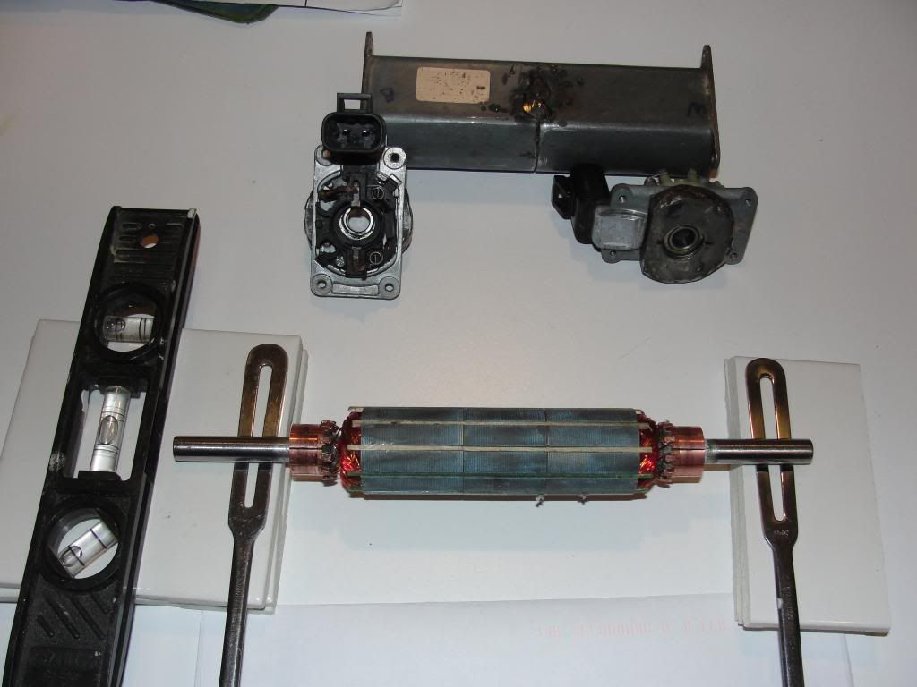
    This motor is too stiff to turn yet, no where as loose as my QP10. Gotta look at brush tension again, pretty sure it isn't binding. If the brushes are sharing the amperage equally then I got more rpm for the same load when running both sets in parallel. The commutators are looking kinda dirty too.
    Mechanical drag, due to misalignment or rubbing parts is a killer for performance my friend...

    You can see my QP10 run on UFO's site where I earned honors for that job!

    So working toward some better results...
    That housing (on video) looks much better than the smaller magnets circumference/semi-rectangular type...you must realize that even powering just one brush set within four magnets you will get assisting on the reversing coils right after collapse...you do not have that option on the latest one.

    The second draw back on this type (rectangular housing) is that you could not adjust brush timing...and all this motors need a "final tuning" after first run...I do it while running...and meters on...to check best point at RPM's and Output.


    Regards


    Ufopolitics

    Edit 1: Sam, after reading your mail...I realized something...on the Group Windings...we are spreading the magnetic fields...not as compact as in Pairs all north...therefore, we need to either add same wire than pairs, per coil...or use heavier gauge to make fields stronger (per coil) at Group Winding.
    Last edited by Ufopolitics; 05-05-2014, 12:09 PM.
    Principles for the Development of a Complete Mind: Study the science of art. Study the art of science. Develop your senses- especially learn how to see. Realize that everything connects to everything else.― Leonardo da Vinci

    Comment


    • Re: Ufo comments to GM unipolar group winding replication

      Originally posted by Ufopolitics View Post
      Good job Sam!
      When you powered both brush sets...you meant like parallel connect?...or with a rear jumper and top feed?
      That's a lot of amps drop off
      yes sure was, I cant say exactly which end got the positive connection, when as a generator reading, one end got 8v, I think it was + to - to + to -, but one way it would run, and the other you got an intense negative reaction, probably fighting the natural rotational forces, like it wanted to stop cold, immediately, with a sudden jerk and sparking.
      One question...are this two motors (Quad and G-10) same spec's as rotor wise?...If so, could you run the G-10 Rotor inside the Quad Stators/Brushes housing?
      no can do. The dual stator was a double rotor - 4", the quad was 2". I hoped to make up for it being only a dual stator by making it longer, and of course, putting the two bodies together was easier, since you could duplicate the original motor's brush and endplate assembly to the commutator placement, no thinking and simple measurements to dupe.
      The second draw back on this type (rectangular housing) is that you could not adjust brush timing...and all this motors need a "final tuning" after first run...I do it while running...and meters on...to check best point at RPM's and Output.
      yes absolutely no adjusting. I think a big drawback now to these motors is the magnet's are shorter in width as I posted earlier on this page. The motors are made to be narrow to fit in a door Bad for doing real work as I have some plans on seeing how much energy it can make. But I am happy with the ohms per group and heating seems very under control and will look at 24v. I think I used 26ga on the quad and it had .6-.7ohms per coil, and the brush assemblies are just not heat tolerant, failed a brush set fast (haven't disassembled yet to find out exactly). Pretty sure its best to pursue your unipolar windings though instead. I would rather rewind it that way, before I do anything serious with it. I might try to repair it just to get good comparisons to the unipolar. I would almost say that I should go up a gauge to 27ga on it also, since it ran so hot. But maybe need to get the pulsers working to see how they help.
      Edit 1: Sam, after reading your mail...I realized something...on the Group Windings...we are spreading the magnetic fields...not as compact as in Pairs all north...therefore, we need to either add same wire than pairs, per coil...or use heavier gauge to make fields stronger (per coil) at Group Winding.
      I have enough rotors and commutators to make a new motor core methinks pretty quickly. Many serious home front priorities now however. Yes could there be a possibility that your original RS unipolar pairs is a better design? A new rotor winding of that type would be the ticket to answer that!
      Up, Up and Away

      Comment


      • Group Windings...

        Originally posted by sampojo View Post
        yes sure was, I cant say exactly which end got the positive connection, when as a generator reading, one end got 8v, I think it was + to - to + to -, but one way it would run, and the other you got an intense negative reaction, probably fighting the natural rotational forces, like it wanted to stop cold, immediately, with a sudden jerk and sparking.
        Hey Sam,

        Next time try to remember when this happened on the bold letters above...it is important to know in which connection this counter force effect occurred.

        no can do. The dual stator was a double rotor - 4", the quad was 2". I hoped to make up for it being only a dual stator by making it longer, and of course, putting the two bodies together was easier, since you could duplicate the original motor's brush and endplate assembly to the commutator placement, no thinking and simple measurements to dupe.
        In this research and development we are all in... it is great to be able to switch models...like having a solely housing assy, where a few armatures/rotors fit perfectly...and maybe of different pole numbers would be even better....but still being same number of poles, like in your case 10...to make a Group and a Pair config all north...then run tests on the same housing...saves time, money...and come up with results much faster...all we need to do is to film them separate...then add a video with both comparisons.

        It would clear all doubts right now...as which one of the windings works out better.


        yes absolutely no adjusting. I think a big drawback now to these motors is the magnet's are shorter in width as I posted earlier on this page. The motors are made to be narrow to fit in a door Bad for doing real work as I have some plans on seeing how much energy it can make. But I am happy with the ohms per group and heating seems very under control and will look at 24v. I think I used 26ga on the quad and it had .6-.7ohms per coil, and the brush assemblies are just not heat tolerant, failed a brush set fast (haven't disassembled yet to find out exactly). Pretty sure its best to pursue your unipolar windings though instead. I would rather rewind it that way, before I do anything serious with it. I might try to repair it just to get good comparisons to the unipolar. I would almost say that I should go up a gauge to 27ga on it also, since it ran so hot. But maybe need to get the pulsers working to see how they help.
        Yeah, that's a draw back on the window regulator motors...this motors need adjustments...not only at neutral timing everything is gonna work out just fine...plus, the other thing is...this motors have a pretty small sized circumference...if you notice the commutators are almost same size as rotor...not good either, in order to have high RPM's we need the rotor drum to be pretty wide...taking it to any scale...small or large types.

        For example, look at the Radio Shack motor...pretty big circumference rotor for its size...then look at its commutators...very thin...small timing there...


        I have enough rotors and commutators to make a new motor core methinks pretty quickly. Many serious home front priorities now however. Yes could there be a possibility that your original RS unipolar pairs is a better design? A new rotor winding of that type would be the ticket to answer that!
        The Group Windings favors the Generating side of this Machines...not as much the Motoring side...

        The ideal deal, would be to obtain a way to please both worlds without the need to do separate windings for each operation (motor and generator)...and I believe we are closer to achieve this in Group windings, rather than Pairs.

        But definitively the "All North" design prevails over the North-South old concept...there is absolutely no doubt about that fact.

        In order to understand why Groups benefit generation of electricity is simple.

        In Pairs we have exactly Four Columns of vertical wires that Generate electricity passing in front of stators magnetic fields...no matter what configuration or number of poles we have...and out of those four columns, we have two that are exactly within same space-time sweeping the magnetic field.

        All those attributes above are not good for generating electricity...however, for motors they are excellent.

        In Groups...we could bring your ten pole as an example...then realize we have Four Coils in each group...that have Eight vertical columns of wires...where only TWO(2) are sharing same slot (Coil 1 end & 3 start)...and all those seven columns are running through the magnetic fields at different times...which enables a huge generating gaining potential through time (RPM's)...actually typical generators are wound exactly like this.

        On the Motor side, like I said on my previous post...Groups winding widens what is a very centered/compact in Pair type, related to bisectors/center of the rotor magnetic fields...this weakens the strength of each interacting motoring field...

        But I already figured out a possible solution...an alternative to favor both worlds, using same type of coils modules...and that is to wind them with heavier gauge trying to add as many turns as we could, per each coil in the group...depending on each different configurations allow Us to do, of course.

        Heavier Gauge wire will generate a stronger field for motoring, even with lesser turns than we may have had in Pairs configuration...plus heavy gauge will generate pretty high currents (amperage), electricity.

        Anyways Sam...I believe until we build a Four Stator system with Groups in a large motor...we will not know for sure if they will be successful or not...We need Systems that are "compatible" with all kind of configurations...either Two, Four or Six Stators (MAG3)...

        Take care


        Ufopolitics
        Principles for the Development of a Complete Mind: Study the science of art. Study the art of science. Develop your senses- especially learn how to see. Realize that everything connects to everything else.― Leonardo da Vinci

        Comment


        • The activity of the animal beings has become acutely active everywhere on this earth. Bodies do not get time to booty a blow for a while. With the accretion use of altered gadgets of Gps Jammer, the possibilities of accepting the aboriginal of blow accept absolutely finished. The adaptable phones or the corpuscle phones are some of these accessories that accumulate the bodies consistently in blow with the alfresco world. The adaptable building are additionally accessible about everywhere these canicule and due to this the accessibility of the cell phone jammer for sale has become alike added quick and authentic. Today, you cannot break out of ability of these adaptable building as their signals can bolt your about anywhere. The bearings of bodies who accord to altered business professions has become actual analytical of wifi jammer as their authorities bolt them anywhere any moment.

          Comment


          • Self Accelerating Process/Battery Voltage Gain.

            Hello to All,

            https://www.youtube.com/watch?v=k4fJEf_WRHg

            Above is a Video I have been working on for a while*...it's about the same small Radio Shack Five Poles (ALL NORTH TYPE)...except this time I wound it with 26 awg (green wire from RS)...and only Eight(8) Turns per Coil in the Pair...delivering anywhere between 0.8 to 1.1 ( just wound)...and it could drop to 0.5~0.6 after a few runs... ...yes, that is correct, and that is why I keep saying it varies...depending on many factors...basically room temperature...operating temperature...our meters processor "interpretation"...copper alloy, etc,etc...but, the way to go is by 8 turns, 26 awg, or 16 total at each Pair.

            *I had issues with this Motor in the beginning as you will see on vid...PLUS, also do not expect this "Effect" to manifest anytime...or just by turning On Motor it would be there, like turning the On switch of a brand new appliance ...sometimes it takes a while...and some times it just don't do it...so it is not simple to capture on video like I did...I had run SEVERAL TAKES...that were non successful guys...and finally, I am very happy I did it, capturing to be able to share it with you all...This means...this is something we need to work on...and develop it MUCH further...trying more number of turns...or lesser...and checking results...that's what "development" is all about Guys...many testing...failed and good tests...are both needed to come up with excellent results, excellent and final conclusions.

            This type of winding develops/runs with LOTS of Amperage within its core for its size...and surprisingly there are NOT Sparks on commutators at all...nor motor gets hot...So if it does, something is wrong on your set up...or a huge mechanical drag.

            Now, I am NOT claiming we are recharging batteries by running this way at least not on this video, not with this type of motor...this type of batteries (NiMh) have a complicated process, like a "Ritual" to be charged properly...and we are just "randomly" shutting charges back and forth from Batteries and Motor, through same Input Wires (Notice I do not have Output connected back to batteries through diodes, etc,etc)...I am just momentarily storing output on a small cap (parallel to meter) and reading them with second Meter at Left ...so we could do the Math and add those values up...to find out machine is almost using zero voltage to run...

            Motor when first connected start at certain speed...then start increasing RPM's...while Voltage (at Input Meter basically) start climbing up...then comes down...then up...and so the speed...til it "settles" at a certain range.

            I do not recommend to run this type of winding on too higher voltages above 3.0~4.0 Volts...unless you have a very solid build model...and pretty well aligned and secure housing when doing it!...realize on this video I am only using 2.5 Volts.

            Do not use LiPo's unless you add a controller between, to regulate disbursement of charges...and keep around those voltages I have mentioned above.


            Enjoy


            Kind Regards


            Ufopolitics
            Last edited by Ufopolitics; 05-10-2014, 04:17 PM.
            Principles for the Development of a Complete Mind: Study the science of art. Study the art of science. Develop your senses- especially learn how to see. Realize that everything connects to everything else.― Leonardo da Vinci

            Comment


            • It always seems impossible until it's done... Nelson Mandela

              Comment


              • my first motor

                hello everyone, first of all like to thank everyone who showed their experiences in this forum , and especially to our mentor , Mr. UFO . This is my first post , I have studied this very subject. But like most , I'm just an enthusiast, and I have not knowledge to understand this whole process, besides the difficulty of the language , because I am Brazilian. Seeing the work of our mentor, wanted to try something different . If you need only a motor mechanic to move something , I figured it could remove the generator of the motor winding , and with it , the asymmetry could improve engine performance by facilitating the assembly process , leaving only a commutator. Originally my motor is a DC motor treadmill: 3HP , 90 v , 18 poles and 02 magnets. I made the winding according to the model of 12 poles . Not withstanding temptation , put to work immediately, even without having completed all .... excuse me . Result, in the brush got: 1.3 ohms , 24 V and 16 A. I got a good torque to hold the shaft with two woods . Much force was needed to try to stop the engine . Having limited knowledge on this subject , I would like to hear from you what you can expect from my testing , as well as what I could do to repay all that I learned . The fact is that I was very happy with the result . Thank you again .
                Attached Files

                Comment


                • In modern times. there are various kinds of secure devices to provide safe environment for people. For example the security camera can be used to monitor suspicious person come and go in the office or people's own home. Besides the florida vehicle inspection also can be used to set up a security system to ensure our safety in the daily life.

                  Comment


                  • Kogs update on Nessie

                    Originally posted by iankoglin View Post
                    G'day UFO
                    I have almost all the electronic parts to complete Nessie's Heart
                    I am about to assemble this circuit for Nessie and really would like to be able to switch the motor in reverse
                    What is required to switch the motor and Cap bank could I use a rotary say an 8 Pole double throw and where should I place it I imagine it should be at the Motor before the DPDT 50 amp toggles.

                    I am in the process of testing the 1000w motor I will make a video both with a copy of the original 6 Mosfet circuit like I have in the lighting of the 5 CFL bulbs and then another one with JS. Monster

                    when I finish Nessie and you are satisfied with the all North P56 I will wire one I have here,
                    Kindest Regards My Friend
                    G'day UFO
                    While I am waiting for my Reverse switch and 5 pin relays I expect to place the order from China this week and they said I should have them in 5 days

                    I decided to try the recharging of my batteries by using the Gen output
                    I am trying this out first with my 20pole 250w motor one of the ones I had varnished and balanced. I had 8 wires coming out one from each brush and using different configurations copying the setup you designed for Nessie.
                    the first setup was using one power set of brushes and the other 3 sets to charge the motor got HOT. I tried using 2 power sets of brushes and 2 Power sets of brushes the same thing the motor gets hot, I then had the gen sets of brushes in series the motor still gets hot about 32deg. C and climbing.
                    Please UFO how hot can these motors run Usually they run cool If I don't use the gen input the motors seem to run cooler.
                    I tried to adjust the position of the brushes to the stator magnets the motor runs slower and draws more amps

                    I did not really keep any data as I was just fiddling with things to see how to connect everything I am using 8 capacitors 63v and 22000uf each in Parallel the volts to run the motor is 24v
                    Kindest regards my friend


                    Kogs Nessie Still a Lady in Waiting

                    Comment


                    • Originally posted by iankoglin View Post
                      G'day UFO
                      While I am waiting for my Reverse switch and 5 pin relays I expect to place the order from China this week and they said I should have them in 5 days

                      I decided to try the recharging of my batteries by using the Gen output
                      I am trying this out first with my 20pole 250w motor one of the ones I had varnished and balanced. I had 8 wires coming out one from each brush and using different configurations copying the setup you designed for Nessie.
                      the first setup was using one power set of brushes and the other 3 sets to charge the motor got HOT. I tried using 2 power sets of brushes and 2 Power sets of brushes the same thing the motor gets hot, I then had the gen sets of brushes in series the motor still gets hot about 32deg. C and climbing.
                      Please UFO how hot can these motors run Usually they run cool If I don't use the gen input the motors seem to run cooler.
                      I tried to adjust the position of the brushes to the stator magnets the motor runs slower and draws more amps

                      I did not really keep any data as I was just fiddling with things to see how to connect everything I am using 8 capacitors 63v and 22000uf each in Parallel the volts to run the motor is 24v
                      Kindest regards my friend


                      Kogs Nessie Still a Lady in Waiting
                      Hello Kogs,

                      Related to adjusting Motor...you should reach the fastest (speed rate) at Lowest Amps draw.

                      Now, are you using diodes to block batteries being charged preventing them to energize back the gen out?...then verify the diodes are doing their "blocking job" by using LED's Test lamps.

                      Kogs...32ºC is 90ºF...and that is NOT Hot at all friend!...check the Temp Running spec´s of your original Motor...then compare to those degrees.

                      In my last video my little Radio Shack Motor was running at 95ºF...and getting up to 100+...that is "warm"..


                      Regards


                      Ufopolitics


                      P.D:Our "normal" room temperature in Florida is 88ºF...
                      Principles for the Development of a Complete Mind: Study the science of art. Study the art of science. Develop your senses- especially learn how to see. Realize that everything connects to everything else.― Leonardo da Vinci

                      Comment


                      • Originally posted by flaviop View Post
                        hello everyone, first of all like to thank everyone who showed their experiences in this forum , and especially to our mentor , Mr. UFO . This is my first post , I have studied this very subject. But like most , I'm just an enthusiast, and I have not knowledge to understand this whole process, besides the difficulty of the language , because I am Brazilian. Seeing the work of our mentor, wanted to try something different . If you need only a motor mechanic to move something , I figured it could remove the generator of the motor winding , and with it , the asymmetry could improve engine performance by facilitating the assembly process , leaving only a commutator. Originally my motor is a DC motor treadmill: 3HP , 90 v , 18 poles and 02 magnets. I made the winding according to the model of 12 poles . Not withstanding temptation , put to work immediately, even without having completed all .... excuse me . Result, in the brush got: 1.3 ohms , 24 V and 16 A. I got a good torque to hold the shaft with two woods . Much force was needed to try to stop the engine . Having limited knowledge on this subject , I would like to hear from you what you can expect from my testing , as well as what I could do to repay all that I learned . The fact is that I was very happy with the result . Thank you again .
                        Portugués:

                        Oi Flavio,

                        Muito obrigado!

                        Se você não está alterando as configurações originais como o meu motor ... acho que posso ajudá-lo?

                        Um não elimina o gerador comutador elimina as configurações ... assimétri completa.

                        Com um único comutador você está invertendo a polaridade (de tensão e magnéticos) enrolamentos independentes em cada volta de 180 º

                        Eu acho que você está confundindo tecnologia minha assimétrico com Alexander.(mostrado abaixo)

                        Español:

                        Hola Flavio,

                        Muchas gracias!

                        Si tú estás cambiando la configuración original de mi motor...como crees que puedo ayudarte?

                        Un solo commutador no elimina el generador...elimina la completa configuración asimétrica.

                        Con un único commutador estás invirtiendo la polaridad (de voltage y magnética) de los embobinados independientes en cada vuelta de 180º

                        creo que estás confundiendo mi tecnología Asimétrica con la de Alexander.(mostrada debajo)


                        English:

                        Hello Flavio,

                        If you are changing the complete configuration of my motors...how do you believe I could help You?

                        Only one(1) commutator does not "remove" the generator from my motors...but the whole asymmetry.

                        One commutator forces to reverse volts and magnetic fields from each independent coil every 180º

                        I believe you are confusing my tech with Alexander´s (shown below).


                        [IMG][/IMG]

                        Saudações


                        Ufopolitics
                        Principles for the Development of a Complete Mind: Study the science of art. Study the art of science. Develop your senses- especially learn how to see. Realize that everything connects to everything else.― Leonardo da Vinci

                        Comment


                        • First run - kinda

                          Ok it was a rainy washout kind of day, so I thought I would work on my 5 pole goldmine motor.
                          After seeing UFOs latest success with 26 gage wire on his RS motor I thought that I would be experimental and try 22 gage. Every pair showed exactly .03 ohms on my Fluke.
                          Now my craftsmanship I have to be honest is probably a little bit lacking compared to alot of you other builders but hey were experimenting - right?
                          Knowing that I needed secure the wires better I wanted to test it to make sure it was going to run before I started slathering it with glue. I just bumped it with 10 volts and it shot to life just long enough for one of my wires to come loose and wedge between the rotor and one of the magnets. It didn't break the wire fortunatley but it did wear the enamel off so I will have to recoat it. I know that it is going to run so I'll go ahead and secure the wires while I'm at it. Not shur when I'll get back to it but more to come. I'll try to get some readings and also try to figure out a way to get some pics posted.
                          Oh yah I should have mentioned that was 8 turns per coil 16 per pair as UFO suggested.

                          Comment


                          • Zardox

                            Originally posted by Zardox View Post
                            Ok it was a rainy washout kind of day, so I thought I would work on my 5 pole goldmine motor.
                            After seeing UFOs latest success with 26 gage wire on his RS motor I thought that I would be experimental and try 22 gage. Every pair showed exactly .03 ohms on my Fluke.
                            Now my craftsmanship I have to be honest is probably a little bit lacking compared to alot of you other builders but hey were experimenting - right?
                            Knowing that I needed secure the wires better I wanted to test it to make sure it was going to run before I started slathering it with glue. I just bumped it with 10 volts and it shot to life just long enough for one of my wires to come loose and wedge between the rotor and one of the magnets. It didn't break the wire fortunatley but it did wear the enamel off so I will have to recoat it. I know that it is going to run so I'll go ahead and secure the wires while I'm at it. Not shur when I'll get back to it but more to come. I'll try to get some readings and also try to figure out a way to get some pics posted.
                            Oh yah I should have mentioned that was 8 turns per coil 16 per pair as UFO suggested.
                            Hello Zardox,

                            Please, read my previous post where I uploaded video...I recommend NOT to go above 3.0 to 4.0 Volts with this wind type...

                            Second, if you have 0.3 is TOO LOW, you need least 0.5 Ohms my friend...and the coils will reduce even more resistance once hot running (at least they did it on mine)

                            So, pls, check before running it again...and you may need to go 10 turns each coil instead of 8...then measure again.


                            Regards


                            Ufopolitics
                            Principles for the Development of a Complete Mind: Study the science of art. Study the art of science. Develop your senses- especially learn how to see. Realize that everything connects to everything else.― Leonardo da Vinci

                            Comment


                            • Ufo,
                              at no time thought it was changing its configuration. I made a sketch of what I think about your engine (sorry for the bad traits made, but I believe they help to justify my point of view). Seeing how each coil is made, I dont think nro 1 drawing, represent in fact what is your engine. This figure does not show the big difference in your engine, which is the change of direction of the winding, from CW to CCW, which occurs between 0 º and 120 º, and 360 º to 240 º. I think when these coils are energized, these half 120º of the coil, will always leave the asymmetric system, and not the position of input and output of the commutator. The resulting magnetic field across the coil, with its phase inversion, they form a dipole or a toroid with V-faces, and that is what would asymmetrical system. In Figure 2, we see this change in direction of coil winding, with its 02 commutator. In figure 3 shows the generator, that is, when the input coil is "energized" induces a current in the coils to turn, AB coil inducing CD coil. Seeing her figure 5, in connection with the series, I thought that the second switch would run just like a resistor between the AB and CD coils. Thus thought the corresponding circuit would be similar to that of Figure 4. Figure 6 demonstrates that imagined at the end of it. 7 exactly the shape and local input and output commutator. Where my mistake was evident with the creation of a new asymmetry in the output coil, since the entry in a 45 º and 90 º output. Sometimes my engine was not starting, need to move a few degrees to init functioning. Yesterday he went to the balancing, let's see what happens. Does thought wrong? Thank you for listening. I await your considerations and all who are following this brilliant topic.

                              ps.: once again, sorry for any mistranslation.
                              Attached Files

                              Comment


                              • Kogs update

                                Originally posted by Ufopolitics View Post
                                Hello Kogs,

                                Related to adjusting Motor...you should reach the fastest (speed rate) at Lowest Amps draw.

                                Now, are you using diodes to block batteries being charged preventing them to energize back the gen out?...then verify the diodes are doing their "blocking job" by using LED's Test lamps.

                                Kogs...32ºC is 90ºF...and that is NOT Hot at all friend!...check the Temp Running spec´s of your original Motor...then compare to those degrees.

                                In my last video my little Radio Shack Motor was running at 95ºF...and getting up to 100+...that is "warm"..


                                Regards


                                Ufopolitics


                                P.D:Our "normal" room temperature in Florida is 88ºF...
                                G'day UFO and Team
                                I made another attempt at putting the out put back into the battery
                                the car batteries are ones I am in the process of rejuvenating when I got the batteries they would not hold a charge at the moment I would say they are half way to being completely rejuvenated
                                The Motor has 2 sets of brushes the Motor brushes are in parallel and the Generator brushes are also in parallel.
                                You notice that the battery is connected to top of both comms and the output is directly taken from the 2 bottom coms to the Cap bank of 8 12000uf 63v caps in parallel with a Diode on each Negative into and out of the Cap Bank

                                I have the video on YouTube here
                                MY 250w 24v output into cap bank back into24 car battery - YouTube

                                The voltage of the batteries started @ 24.9v rested from charging and finished up24.10v @ 3:00pm and @ 3.25 hours after I finished the video 6:15pm the batteries were rested @25.07v and still after another 1:40 later @7:55 the volts finished @25.12

                                When I started the video I only had the pot about between 1/2 and 3/4 on
                                You can notice how the Amps went up when I put the Pot full on at 2:42
                                then the Amps quickly jumped and settled down
                                The temperature I am not really satisfied as it went up progressively until it reached 61.9C (144f) I do not know how the batteries will go in Nessie as I was not going to ventilate them But I see now I will have to fan them to keep them cool
                                I will do a different test after I Re Charge the Batteries and post again

                                Kindest regards to all

                                Kogs still at work

                                Comment

                                Working...
                                X