Announcement

Collapse
No announcement yet.

My Asymmetric Electrodynamic Machines

Collapse
X
 
  • Filter
  • Time
  • Show
Clear All
new posts

  • Not winding yet

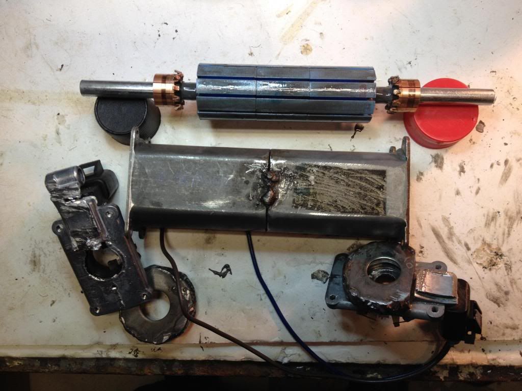
    Still gotta fasten those bearing housings on the motor endplate. Darn brush wire came loose, look like it was soldered to the exterior connector. Man this one wasnt welded, like it was repaired. Hope it holds, cant braze it now.

    I think the rotor looks nice...

    Last edited by sampojo; 04-14-2014, 02:59 AM.
    Up, Up and Away

    Comment


    • 4 stator....?

      @UFO,

      I was thinking that when I was looking at the diagram...It looks like the coils will always be opposite...at least for even numbered poles with 4 stators...The 2 stator is more like tesla's design...Let me know if you think this design will work with 4 stators...otherwise I will work on getting those magnets switched around.

      Warrensk

      Comment


      • It Will...

        Originally posted by warrensk View Post
        @UFO,

        I was thinking that when I was looking at the diagram...It looks like the coils will always be opposite...at least for even numbered poles with 4 stators...The 2 stator is more like tesla's design...Let me know if you think this design will work with 4 stators...otherwise I will work on getting those magnets switched around.

        Warrensk
        Hello Warrensk,

        Yes, it will work on Four Stators, of course...We just need to make certain tests to see which way would be more successful in performance.

        I will upload it later on

        Regards


        Ufopolitics
        Principles for the Development of a Complete Mind: Study the science of art. Study the art of science. Develop your senses- especially learn how to see. Realize that everything connects to everything else.― Leonardo da Vinci

        Comment


        • My1016

          Originally posted by warrensk View Post
          Hey UFO,

          Ive got another pair of MY1020's coming...I just realized all the new concepts are for a 2 stator system...I will wait patiently to see your results with the 4 stator/4brush system...A ten pole 4 stator system can be done too. Let me know if it can be applied simply to 4 stators...


          Could I wind it just as I wound the 16 pole but with all north coils and only 10 poles?


          Or I could wind groups of coils in between where the pair would have occupied? Would the angle be alright?

          Warrensk
          Hey Warrensk,
          I've got a pair of my1016's and was wondering how you got the commutator on to the larger shaft in the front of the motor?

          Did you mill it down or what? I know the front and back shafts are different sizes.

          Or are the my1020 made different?

          Thanks,
          wantomake

          Comment


          • Commutator....

            Hey wanttomake!

            I went to home depot or lowes...any hardware store... and I got a 3/8ths inch bolt thing...And by bolt thing I mean a long shaft without a head on it...so it is pretty much a long 3/8ths in shaft...I then put the motor core on that, had a bunch of 3/8in washers in between the motor core and the commutators. I think I used like 15 washers on each side...Then comes the commutators and then I used a 3/8th in nut on each end to press the whole thing together...This worked pretty well for me. Make sure you leave enough room for the wires (space between commutator and motor core) Some laminations from the core may need to be removed...

            Hope this helps, Ive made the 1016s before...I wound that motor 2 times, the 1020s are the same construction but have 20 poles instead of 16

            Warrensk

            Comment


            • Thanks

              Originally posted by warrensk View Post
              Hey wanttomake!

              I went to home depot or lowes...any hardware store... and I got a 3/8ths inch bolt thing...And by bolt thing I mean a long shaft without a head on it...so it is pretty much a long 3/8ths in shaft...I then put the motor core on that, had a bunch of 3/8in washers in between the motor core and the commutators. I think I used like 15 washers on each side...Then comes the commutators and then I used a 3/8th in nut on each end to press the whole thing together...This worked pretty well for me. Make sure you leave enough room for the wires (space between commutator and motor core) Some laminations from the core may need to be removed...

              Hope this helps, Ive made the 1016s before...I wound that motor 2 times, the 1020s are the same construction but have 20 poles instead of 16

              Warrensk
              Thanks for the reply Warrensk,

              I looked up the specs after the last post. The 1020 seems to have more space to work with on each end. My problem is the machine to press the core off in order to do what you did.

              I'm trying to build this again to use as a smaller scale of the Lockridge device project. This device is best motor/generator I've ever put a fluke meter on. Ufopolitics is big help and support with attributes out of this world.

              Again thanks. And thank you Ufo for all of this.
              wantomake

              Comment


              • Core

                @wantomake,

                Project sounds interesting, this motor/generator is one of the best designs out there. They can be applied to so many things. Make sure to burn the motor really well and remove the commutator before burning!!! The shaft can be hammered off...I put the core on PVC pipe so the shaft could be hit out. It didnt take tooo much effort. When It gets down in the core, I used an old screw driver to hit it the rest of the way out.

                warrensk

                Comment


                • Four Stators, All North Asymmetric Analysis...

                  Hello to All,

                  Below is a 20 Pole, All North, Four Stator Asymmetric Machine...

                  [IMG][/IMG]

                  I have just displayed the Two Groups Interacting at Each Motor Brushes...So We have G1-G2 being energized by Motor-1 Brushes , as also G11-G12 at Motor-2 Brushes, apart by 180º...All Four Groups are projecting North towards Stators, creating a simultaneous Repulse-Attract action.

                  I have detailed G1 by showing Coil (1) on both ends, in order to realize is in charge to create the closest point of Repulsion against Stator N1...While Coil(4) is "the furthest" of the Group, towards South Stator S1...therefore creating the closest Attraction on S1.

                  It is EXTREMELY IMPORTANT at this specific point, where TWO GROUPS are making Contact...that we Observe G2 (or any numbered Group which is "Ahead" or in "Progression" according to Rotation R) and MAKE SURE...the furthest Coil CENTER/BISECTOR is NOT ALIGNED with Stator Bisector (S1) while contacting Brush-Comm Element...verifying G2 DISCONNECTS BEFORE REACHING S1 CENTER....Once this is done in just one Group Coil, ALL Others will fall within same sequence.

                  Finally I have shown the Two South Fields this Four Groups are generating towards center shaft...defined by two arrows areas pointing center shaft.

                  Now let's look at what happens when Generating Coils comes into play...

                  [IMG][/IMG]

                  In the above Diagram I have Incorporated the TWO GROUPS ON EACH SIDE (G6/G7-G16/G17)that HAVE BEEN DISCONNECTED FROM INPUT, and are entering/leaving respectively, GEN-1 and GEN-2 Brushes.

                  FIRST, We must realize that this Groups are "swinging Voltages" while disconnected from Source/Input, towards a REVERSED polarity that WILL FAVOR a Generation of a SOUTH FIELD projecting towards Stators "Naturally", meaning "Not Forced"...

                  SECOND, We must "see" (not shown on Diagram though) the Two B FIELDS VECTORS that are there at all time between N2 to S1, and between N1 towards S2...If We then note Rotation R, those Groups are traveling towards those Two B Fields, Inducing a Current that would generate Opposite B Fields (Lenz)...then they will ALL in Generation Stage will become South projecting towards Stators...and North towards Center Shaft...This effect will "Open a Gate" for the Two Repelling South Fields coming out of Groups at Input/Motor Stage...So, a REDIRECTION/DIVERTING of SOUTH Fields will take place here...being Attracted by the Inner Norths...REINFORCING the Generated by Induction OUTER South Poles on the Green Groups...assisting Rotation, instead of opposing it.

                  THIRD, We then must realize that by adding ANY Closed circuit Load at this GEN GROUPS will be closing the Coils into a Loop or strengthening their South Fields Forces...then an Acceleration Under Load will occur when we do that...no magic...just a simple "fooling" of opposed B FIELDS, plus the correct timing in Space positioning...

                  RESUMING:

                  1-When We disconnect a Coil/Inductor (or Collapse) we could say -not to create confusion nor arguments again- that Inductor/Coil "Becomes Less North" when it "swings" its voltage polarity at terminals.

                  2-By Coils being all North, same direction, both will become South...when passing through an Exciting Field (Stators)...that Induction flow, "favors" the collapsing swinging of voltage.

                  Therefore, at least two favorable occurrences here are assisting rotation, then finally closing up/looping Coils at that moment will strengthen magnetic field, South in this case.

                  Finally, let's review our older method to wind...where we had a North and a South Coils in each of the Pairs...The advantages are clear...only "Half of the Pairs" (or those North) will benefit rotation under load.

                  Still We have to keep making further testing on this type of Machines...and only building them We will get to find out...


                  Regards to All


                  Ufopolitics
                  Last edited by Ufopolitics; 04-17-2014, 12:51 AM.
                  Principles for the Development of a Complete Mind: Study the science of art. Study the art of science. Develop your senses- especially learn how to see. Realize that everything connects to everything else.― Leonardo da Vinci

                  Comment


                  • UFO

                    What are your thoughts on the groups of 5?


                    Keep it Clean and Green
                    Midaz

                    Comment


                    • Groups of Five Poles on a 20 Poles...

                      Originally posted by Midaztouch View Post
                      UFO

                      What are your thoughts on the groups of 5?


                      Keep it Clean and Green
                      Midaz
                      Good question Midaz,

                      It is not a Mistake...I have realized the Five Pole for each coil in the Group of my previous 20 Pole Diagram will bring too close, widen too much the Rotor North Bisectors Angles...and I feel more comfortable with Four...


                      Thanks


                      Ufopolitics
                      Principles for the Development of a Complete Mind: Study the science of art. Study the art of science. Develop your senses- especially learn how to see. Realize that everything connects to everything else.― Leonardo da Vinci

                      Comment


                      • Originally posted by Ufopolitics View Post
                        Good question Midaz,

                        It is not a Mistake...I have realized the Five Pole for each coil in the Group of my previous 20 Pole Diagram will bring too close, widen too much the Rotor North Bisectors Angles...and I feel more comfortable with Four...


                        Thanks


                        Ufopolitics
                        I know you didn't make a mistake.


                        My thoughts are in the difference between amperage and voltage output. Which would give you a stronger amps output, groups of 4 or Groups of 5?

                        Keep it Clean and Green
                        Midaz
                        Last edited by Midaztouch; 04-17-2014, 01:09 AM.

                        Comment


                        • Bisectors

                          Hi Midaz
                          -I am going to try and answer that in order to test my own understanding of what UFO has just presented. In the above diagram he stated that it was very important that the leading rotor bisector must not be aligned with the stator bisector. I believe if you added a fifth coil to the group you would have exactly that problem.

                          Comment


                          • Originally posted by Zardox View Post
                            Hi Midaz
                            -I am going to try and answer that in order to test my own understanding of what UFO has just presented. In the above diagram he stated that it was very important that the leading rotor bisector must not be aligned with the stator bisector. I believe if you added a fifth coil to the group you would have exactly that problem.
                            Zardox

                            There are a few ways to wind the groups with the 20 pole. I'm try to understand the magnetic fields. The alignment with the stator would be timing. I guess this is a case of red apples vs green apples. They are the same but different.

                            Keep it Clean and Green
                            Midaz

                            PS. I prefer green apples
                            Last edited by Midaztouch; 04-18-2014, 12:45 AM. Reason: Spelling

                            Comment


                            • Perfect

                              Hi All, The lay-out for the 20 pole is bang on.
                              The only thing is, I think the timing is off by one tooth.??
                              The timing needs to advance ,...after it's up to speed. (variable)

                              UFO, You are right ,....You cannot tie the grounds together.
                              This was why I was getting acceleration under load. I was pulling more amps , for the added load , thus speeding up the motor,...more amps were traveling?

                              They can't be tied together , but can you feed the collapse of one to the other??
                              artv

                              Comment


                              • Originally posted by Zardox View Post
                                Hi Midaz
                                -I am going to try and answer that in order to test my own understanding of what UFO has just presented. In the above diagram he stated that it was very important that the leading rotor bisector must not be aligned with the stator bisector. I believe if you added a fifth coil to the group you would have exactly that problem.


                                Originally posted by Midaztouch View Post
                                Zardox

                                There are a few ways to wind the groups with the 20 pole. I'm try to understand the magnetic fields. The alignment with the stator would be timing. I guess this is a case of red apples vs green apples. There are the same but different.

                                Keep it Clean and Green
                                Midaz

                                PS. I like green apples

                                Hello Zardox and Midas,


                                I have done this simple Diagram where I wrap five poles per coil in just two of the Groups...let's look at it.

                                [IMG][/IMG]

                                One thing I want to make clear...is that IT WILL WORK like this...with Five Poles, as this way this machine would be faster than the Four Poles Coils, just because the Throw Out Angles are bigger...or magnetic fields are wider than a four...

                                What I do not like is that G2 Last Coil (4) Bisector is too close to stator S1 Center or Bisector of its Curve...and if you notice I had to turn Commutator and Poles a bit to achieve best timing...this angles we must calculate an approach under Higher RPM's.

                                Consider also it will add a bit more resistance since longer horizontal wires...than the four.

                                Only way to know is to try both ways...same embodiment, then evaluate results.

                                However, I see this part as the Structural side of the build...while we rather concentrate on keeping analyzing the effects of acceleration under load and other ones as connections without jumpers...just using the two Inputs and collecting from two outputs...etc,etc.


                                Regards


                                Ufopolitics
                                Principles for the Development of a Complete Mind: Study the science of art. Study the art of science. Develop your senses- especially learn how to see. Realize that everything connects to everything else.― Leonardo da Vinci

                                Comment

                                Working...
                                X