Announcement

Collapse
No announcement yet.

My Asymmetric Electrodynamic Machines

Collapse
X
 
  • Filter
  • Time
  • Show
Clear All
new posts

  • Originally posted by GChilders View Post
    @ufoPolitics

    ufo I have stripped the 6 motors from goldmine and put the armatures and commutators on a new shaft and have 3 rotors ready to wind. I just wanted to clear up the wind in my mind because you said something about interleaving the area in the center and also 3 coils. Here is how I see it please correct me if I am wrong. Connect to the top commutator P1 come around rotor P5 continue down slot to bottom of rotor in clockwise direction wind around P1 up on slot left of P1 and then clockwise down on right side of P1 to the bottom of the rotor and then in clockwise direction come up on the slot left of P2 and then in clockwise direction down on slot to right of P1 to bottom of rotor and then up slot to left of P1 continuing to wind clockwise to the slot to the right of P5 and now we are where we started and do this 30 times and then tie off at bottom commutator p1. I think that is right.

    Cheers

    Garry
    Hello Garry,

    Is hard for me to understand by the way you are describing it, I am sorry.
    You are mentioning Three Coils?...but referring to the Five Poles?...or you meant Three Poles for each Pair of Coils?

    One question, did you watch my latest two videos? plus this one below?:

    https://www.youtube.com/watch?v=RSs2beNfAP8

    Can you see the way it goes on this 50 sec 3D CAD?

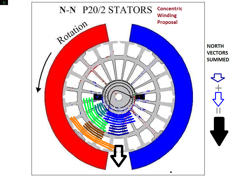
    The Upper brush element in Red is Positive, while the black on bottom is negative, both coils Interleave or overlap at a center common Pole...both wound CW...That's your P1...then do P2 in Aqua color exactly the same way as in Diagram below:

    [IMG][/IMG]

    Notice P2 first Coil (right below its starting element) winds exactly on top of P1 Second/end Coil...and so on.

    Let me know if you understood now...


    Regards


    Ufopolitics
    Last edited by Ufopolitics; 04-08-2014, 02:30 AM.
    Principles for the Development of a Complete Mind: Study the science of art. Study the art of science. Develop your senses- especially learn how to see. Realize that everything connects to everything else.― Leonardo da Vinci

    Comment


    • Please don't rush...

      Originally posted by Cornboy 555 View Post
      [IMG][/IMG]

      Ahhhhhh, UFO, Simplicity, love it.

      I originally was going to scratch build a large three pole, mainly because of the winding simplicity, and the shear volume of heavy gauge wire you can fit on a rotor like that.

      With my MAG3 it would be easy to have 100 x 2mm laminations cut to three pole design, and simply wind the 6 stators to 1xnorth and 1xsouth.

      Of course i won't and cant rush into this just yet.
      Hello Cornboy,

      Please don't rush it...

      The Three Pole I am "re-analyzing" it...not in order to start building Three Poles again!!...

      Like I wrote at end of the second post...let's consider this 3 pole as a "Modular" and "Expandable" into other more complex machines...

      For example...your MAG3 has 36 Poles...dividing it by three (3) gives Us exactly 12 Poles...meaning, You could wind overlapped Coils totaling Groups that extend to 12 poles, then You have Three Groups...BUT, that means those Three Groups would be only the "Interacting Ones" with Stators...NOT YOUR TOTAL OF GROUPS!!...just like I represented on Imperial P1, P8, P15 and P22, but Imperial had 28 total Pairs...understand my Friend?

      In Your design, I have to go by Stator size in order to determine each coil length/number of poles...then calculate per Group Total to be fit between Two Stators range...and so on for the other Four...be patient, your Machine IS "Upgradable" as is, without any major structural changes...That's why was named "Mag 3"...

      One Question arises from the image above friend, When N1 is first energized, would N3 be in repel mode with south stator before the rotor bisector is past halfway, causing momentary opposition to rotation, or does Gravity an rotary momentum, take over??.
      Nope, You are thinking of SOUTH N3 as a solely Magnetic Field, with a bisector on center of Pole...but it is NOT!...N3 South (whenever N3 is not energized) is part of a MAIN Redirected South Field from N1 (while N1 is energized) that DERIVES/SPLITS into TWO Poles (N2+N3)...So it ONLY have ONE Bisector...right at slot between those two Poles.
      And I am describing according to Diagram positioning above...when we get N2 or N3 to be energized the whole thing gets changed/swapped...

      Thanks for all you are doing here UFO,

      Warm Regards Cornboy.
      My pleasure


      Regards


      Ufopolitics
      Last edited by Ufopolitics; 04-08-2014, 03:05 AM.
      Principles for the Development of a Complete Mind: Study the science of art. Study the art of science. Develop your senses- especially learn how to see. Realize that everything connects to everything else.― Leonardo da Vinci

      Comment


      • poles commutators and coils

        @ufoPolitics

        This is the hardest part of understanding your drawings. All of the parts are labeled with the same nomenclature. P1 on both of the commutators and p1 on the rotor body and nothing to describe the slots that are on each side of the rotor p1 - p5. What I am trying to describe is the winding of the first pair of lines the dark blue lines which are wound with three coils on the rotor. If I have that right I will proceed to the second pair of lines. As I look at your renderings you are encompassing 3 of the poles on the rotor with 3 coils being wound simultaneously. One around p5 and p1 then continuing around p1 to wind the middle coil and after that one around p2 and p1 and around p1 again and then continuing to wrap around p1 and p5. After doing this 30 times moving over to p2 and starting a fresh group this time every thing that I just did moves over to p1 wrapping around p2 and then around p2 and p3. Is this the correct procedure or are we wrapping around p5 and p1 30 times and then around p1 and p2 30 times and then moving to the next group? I cannot tell from your renderings the correct procedure. When we wound the north and south poles we wrapped an entire coil on the south 30 winds and then the north 30 times. Interleaving suggests to me that the two coils are being woven at the same time. I am trying to clear this up in my mind. Maybe I will try both methods and see which performs better.

        Cheers

        Garry

        Comment


        • videos

          @ufoPolitics

          Yes I have downloaded and watched all three of these videos. Very impressive performance from that little motor!! Looked at the one you recommended and I am still a little unclear as the wires seem to not interleave with each other but are parallel to each other. It is a minor point and that is why I am asking that you follow through the description of the winding, because I am trying to describe with words and your own nomenclature on the parts of the motor what I am seeing. Obviously not well enough because you didn't understand what I described. No problem I will wind it and see how well it Works.

          Cheers

          Garry

          Comment


          • Trying to Understand

            Originally posted by Ufopolitics View Post
            Hello Cornboy,

            Please don't rush it...

            The Three Pole I am "re-analyzing" it...not in order to start building Three Poles again!!...

            Like I wrote at end of the second post...let's consider this 3 pole as a "Modular" and "Expandable" into other more complex machines...

            For example...your MAG3 has 36 Poles...dividing it by three (3) gives Us exactly 12 Poles...meaning, You could wind overlapped Coils totaling Groups that extend to 12 poles, then You have Three Groups...BUT, that means those Three Groups would be only the "Interacting Ones" with Stators...NOT YOUR TOTAL OF GROUPS!!...just like I represented on Imperial P1, P8, P15 and P22, but Imperial had 28 total Pairs...understand my Friend?

            In Your design, I have to go by Stator size in order to determine each coil length/number of poles...then calculate per Group Total to be fit between Two Stators range...and so on for the other Four...be patient, your Machine IS "Upgradable" as is, without any major structural changes...That's why was named "Mag 3"...


            Nope, You are thinking of SOUTH N3 as a solely Magnetic Field, with a bisector on center of Pole...but it is NOT!...N3 South (whenever N3 is not energized) is part of a MAIN Redirected South Field from N1 (while N1 is energized) that DERIVES/SPLITS into TWO Poles (N2+N3)...So it ONLY have ONE Bisector...right at slot between those two Poles.
            And I am describing according to Diagram positioning above...when we get N2 or N3 to be energized the whole thing gets changed/swapped...


            My pleasure


            Regards


            Ufopolitics
            Hello UFO

            What does it do when the wind is done this way? Just a generalization.

            I am sort of green and I see all of these motors and I can't understand what they are doing different after it is done this way.

            Thanks for a simple answer in advance.

            Mike ps it's like nothing else I know of so I better ask

            Comment


            • Originally posted by GChilders View Post
              @ufoPolitics

              This is the hardest part of understanding your drawings. All of the parts are labeled with the same nomenclature. P1 on both of the commutators and p1 on the rotor body and nothing to describe the slots that are on each side of the rotor p1 - p5. What I am trying to describe is the winding of the first pair of lines the dark blue lines which are wound with three coils on the rotor. If I have that right I will proceed to the second pair of lines. As I look at your renderings you are encompassing 3 of the poles on the rotor with 3 coils being wound simultaneously. One around p5 and p1 then continuing around p1 to wind the middle coil and after that one around p2 and p1 and around p1 again and then continuing to wrap around p1 and p5. After doing this 30 times moving over to p2 and starting a fresh group this time every thing that I just did moves over to p1 wrapping around p2 and then around p2 and p3. Is this the correct procedure or are we wrapping around p5 and p1 30 times and then around p1 and p2 30 times and then moving to the next group? I cannot tell from your renderings the correct procedure. When we wound the north and south poles we wrapped an entire coil on the south 30 winds and then the north 30 times. Interleaving suggests to me that the two coils are being woven at the same time. I am trying to clear this up in my mind. Maybe I will try both methods and see which performs better.

              Cheers

              Garry
              G'day Garry
              The P1 is describing which Pair
              on the armature P1 depicts the centre of the pair
              On the top commutator P1 depicts the starting point of the winding of the pair
              On the bottom commutator P1 Depicts the ending point of the pair
              I hope this helps somewhat

              Kindest Regards

              Kogs trying to help

              Comment


              • Hi Garry,
                Originally posted by GChilders View Post
                ... p1 on the rotor body ...
                I see Kogs tried to clarify already.
                However there is just one basic misunderstanding, as far as I can see:
                "P-1" on the rotor body does NOT mean "rotor pole 1"
                It means "coil pair 1", with the double-sided arrow pointing to the dark blue "wires" of that coil pair.
                and
                "P-1" on the commutator means "commutator element connected to coil pair 1"
                Last edited by marxist; 04-08-2014, 04:59 AM.

                Comment


                • Originally posted by marxist View Post
                  Hi Garry,

                  I see Kogs tried to clarify already.
                  However there is just one basic misunderstanding, as far as I can see:
                  "P-1" on the rotor body does NOT mean "rotor pole 1"
                  It means "coil pair 1", with the double-sided arrow pointing to the dark blue "wires" of that coil pair.
                  and
                  "P-1" on the commutator means "commutator element connected to coil pair 1"
                  G'day marxis
                  You are right but to clarify there is 2 connections one each to 2 commutators
                  They are depicted in the drawings the inner is the Bottom comm element and the outer is the Top comm element

                  Kindest Regards

                  Kogs just clarifying

                  Comment


                  • Originally posted by iankoglin View Post
                    .... there is 2 connections one each to 2 commutators
                    They are depicted in the drawings the inner is the Bottom comm element and the outer is the Top comm element
                    Hi Kogs,
                    thanks for the info, I didn't know that ufo's drawings actually contained all these details. Thanks.

                    Want to take the opportunity to ask: In order to fit experimental motors with a second commutator - which seems to be essential, if one wants to follow ufo's design - one needs to disassemble a second motor, take its commutator and fit that to the experimental motor.

                    How does one get a commutator off the shaft to re-use it on another motor?
                    Do you just twist it off with a pair of pliers?
                    Last edited by marxist; 04-08-2014, 06:00 AM.

                    Comment


                    • third coil

                      @Kogs and Marxist

                      I am not confused about the coil pairs or the commutator connections. It seems that there is a third coil being created between the two pairs. Maybe I am just confused by the use of the term interleave which seems to me to mean that as the pair of coils is being wound a third coil is created between the two main coils. I am trying to clarify if I am understanding that correctly. It seems in the video although it is hard to see that around what is marked as p1 between the two slots a third coil is being wound. Call me crazy but I think that is a significant difference between this wind and all of the other winds. Am I completely off base or do you see that third coil being wound also?

                      Cheers

                      Garry

                      Comment


                      • Taking off the commutator

                        @Marxist

                        I cannot recommend trying to twist off the commutators on a goldmine with a pair of pliers. The center of the commutator on these motors is plastic and very fragile. What I have done and many others also is to drill a 4mm hole in a two by four block of lumber and either put one end of the rotor shaft, after the magnet wire has been stripped, into a vise and press the shaft down. Then take a piece of welding rod and drive the shaft the rest of the way out. Some have left the shaft in and driven another shaft in from that side. I find that the rotors will eventually break if you use this method. I have ordered 4mm drill rod and made new shafts for all of my replications. This has been a very satisfactory solution. After driving the old shaft carefully all the way out you will have a commutator 2 spacer bushings and the rotor body. After I disassemble two motors, I take the new shaft and assemble the new rotor with two of the bushings from one motor and the commutators from both motors. I use epoxy to hold the assembly together. If you don't have a large enough vise to press the pieces of the rotor apart. What I have done in the past is drive them apart with a hammer. This may bend the shaft if not done carefully. I use the same two by four block of lumber and drill a 4 mm hole in it. Put the shaft with the commutator against the block and drive the shaft down to the spacer bushing. Once again pulling out a piece of welding rod or an old shaft that has been ground smooth drive the rod the rest of the way out. I have lost occasionally a rotor and also commutators with this method. handle the hammer with care.

                        Cheers

                        Garry

                        Comment


                        • 2 are a pair. no third present

                          Hi Garry,
                          just saw that you answered my question about salvaging commutators. Thanks.

                          Regarding the "third coil of the pair":
                          I have attached a screen-shot from ufo's video "ALL_NN_FIVE_POLES " https://www.youtube.com/watch?v=RSs2beNfAP8, which shows coil-pair 1.

                          I see 2 coils which make one NN-pair. No third coil present, in my understanding.
                          Let's see what Kogs says.

                          edit: ok, when trying to see your problem, I guess one could say:
                          the coils of the pair "share" one rotor pole (see attached screen shot) and one could probably say, that the wire strands on either side of that shared pole AUTOMATICALLY form a kind of a third coil ...
                          Attached Files
                          Last edited by marxist; 04-08-2014, 07:33 AM.

                          Comment


                          • Originally posted by marxist View Post
                            Hi Kogs,
                            thanks for the info, I didn't know that ufo's drawings actually contained all these details. Thanks.

                            Want to take the opportunity to ask: In order to fit experimental motors with a second commutator - which seems to be essential, if one wants to follow ufo's design - one needs to disassemble a second motor, take its commutator and fit that to the experimental motor.

                            How does one get a commutator off the shaft to re-use it on another motor?
                            Do you just twist it off with a pair of pliers?
                            G'day Marxist
                            If you read from the start of this thread a lot of questions you are asking have been asked and answered already I suggest that you read and look for these answers as it takes time for others to look up these answers by doing so you will find answerers before you ask them
                            Kindest Regards

                            Kogs trying to help

                            Comment


                            • A Generalization...

                              Originally posted by BroMikey View Post
                              Hello UFO

                              What does it do when the wind is done this way? Just a generalization.

                              I am sort of green and I see all of these motors and I can't understand what they are doing different after it is done this way.

                              Thanks for a simple answer in advance.

                              Mike ps it's like nothing else I know of so I better ask
                              Hello BroMikey and welcome,

                              This is about a New Methodology and not just a different way to wind an existing motor "as is"...I will try to explain as a "Generalization". However, "a simple answer" would be kind of hard to "briefly" explain this whole technology, plus DC Motor fundamental knowledge is required for easier understanding.

                              What does it do?
                              We build Motors here, where "unused" Energy flows out, back to our sources to be utilized or stored back.

                              We enhance Motor Performance with this new tech, where Torque and Speed Parameters no longer co-exist as Inversely Proportional (meaning we can only have one Parameter at top performance, sacrificing the second one to lower spec's)...but directly proportional, where Speed and Torque are achieved equally in an ascending curve.

                              This type of Motors would "take" higher potentials ranges (Voltages) as higher densities of Currents (Amperage) where Closed Systems could never afford to "process", since they are limited by closed looping of its rotor coils.

                              STRUCTURAL MODIFYING

                              Motors structure must be modified, as adding a second commutator on the other side of rotor shaft, in some cases shaft must be replaced by a longer one, as outer casing/housing also must be "elongated" to fit the dual commutators rotor assembly.

                              COILS WINDING

                              Once structure is modified, then winding process is also different from existing motors.

                              On any existing Motor the winding is a continuous series looping that closes at the end of last wound coil, meaning, all wires are short circuited...or called "Closed Winding".

                              In my Methodology Coils are Isolated or "Open" related to next ones in the Sequence. In order that each coil gets Energized separately when making contact, then by an action of either repulse or attract, or both, it automatically/mechanically, disconnects from contact, pushing or pulling next Coil in line. Disconnected Coils travel to a second Gate-Brush, where it "exhaust" its charge as an output.

                              This way All Coils get a "brake" or an "idling" stage at disconnection, cooling off, plus getting induced by traveling in front of Stators Magnetic Fields, then reaching Output Stage.

                              Did You see my video ASYMMETRY TO ENLIGHTENMENT ?

                              Did You read my ABSTRACT at Introduction First Page of this Thread?:

                              ABSTRACT

                              A new concept to the Art of Electromagnetic Rotation Methodology, that includes new structuring of the Mechanical Architecture of an Electric Motor and/or Generator or combination thereof, extending to the methods for processing their Input-Output governing data.

                              Static and rotational components, particularly individual isolated groups of coil elements performing dual functions as a Motor and as a Generator at specific angles within the 360 degrees of rotation. An specific and unique feature of this methodology is the non reversal of the input current-voltage polarity within the actuating individual isolated coils during the motor stages, causing a non changing magnetic field pole projection due to a one sense or direction magnetic flux in their respective cores, rotation occurs by switching intervals of On and Off Times at specific positioning, such that a repulsion and/or attraction is constantly obtained at T-On, of individually orderly sequenced North-South poles.

                              This particular switching times On and Off creates a one direction, non colliding electronic flow within the isolated conductive coil elements deriving into a pulsating current dropping to zero (at T Off) to Max V in (at T On), equivalent switching codes as to the electronically controlled Pulse Width Modulation (PWM) utilized to control the current feeding input in Electric Motors and the Input-Output parameters of Power Source Converters, this identical Data-Transfer, based on Pulsed Signals, establishes a common language of operation between machine and input-output control commands, leading into a robust communication protocol.

                              The advantages that comprises a Motor and/or a Generator driven directly from the core by pulsed signals, extend to the incorporation of Optoelectronic s as to replace the Old Fashion, brush-commutator switching systems by an emitting pulsed width modulated (Infrared PWM as an example) or linear optical signal (Signaling steadily where On Off occurs by mechanical-magnetic loosing angle of interaction) to an Optoelectronic receiver connected to the Power Switching Executing circuits, delivering a less friction, low noise, more accurate and precise communication Network.
                              Hope this post will help you to understand it better...


                              Regards


                              Ufopolitics
                              Principles for the Development of a Complete Mind: Study the science of art. Study the art of science. Develop your senses- especially learn how to see. Realize that everything connects to everything else.― Leonardo da Vinci

                              Comment


                              • RE: Magnificence of Three post 6460

                                Originally posted by Ufopolitics Post 6460
                                Hello to All,

                                In a "brief" Conclusion on this First Part: Even though, the FIVE POLE...with the Two redirected South Poles above... are Assisting Rotation...which enhances the Performance over the previous N-S Asymmetric Model...STILL, is reduced in "QUALITY and Quantity" over the THREE POLES Structure...which is obviously amplified at larger angles in comparison to the NARROWER Angle depicted by ONLY TWO POLES of the Five Poles Rotor, Between BOTH MACHINES IDENTICAL STATORS positioning...

                                Ufopolitics
                                I have been thinking alot about this and want to offer another analysis using vectors to represent the magnetic fields. I think the two poles South poles of the 5 pole RS style motor is stronger than the three pole motor south poles, contrary to the above paragraph if I understand it correctly. Here are diagrams of both style rotors with some vector analysis, the 3-pole first:


                                Notice how the vertical brown vector is shorter, and the stronger gray vectors are stronger but cancel each other out. Their strength is lost for use in rotation.

                                Below the RS 5-pole with vectors added:


                                Notice how the brown vectors, the North vertical Y-component is longer and stronger, and the cancelling gray X-component vectors are shorter. Overall the N Y-component should sum up larger and stronger.

                                In general the south pole component contribution to rotation is weaker since it further away from the stators, strength decreasing inversely proportional to the distance, for the most part

                                If the three pole performance is better, I propose that the North pole be examined. Notice how concentrated the North pole of a 3-pole coil will be, since the coil is very narrow. The narrower the coil, the stronger the magnetic force will be at the exit point meeting the stators. Now lets look at a North pole unipolar winding using a 20-pole rotor.


                                Lots of coils coming in at angles, with the X-components all fight each other, losing strength.

                                So the question may be, "How could a motor be wound to minimize cancelling X-vectors?" I propose the following:


                                Although the larger half of a given coil will have a weaker field the inner one will serve to concentrate it. I a bigger motor these coil groups would be done in 2 layers and staggered, maintaining the orientation with its comm segment. Since the inner coils would be farther away, it could have more turns, but that could mean different gauges.

                                And this thought finally wormed its way into my cerebrum. Why not wind the motor just like the three pole, one pole at a time? This might get the most copper on the rotor too, as the above method would leave air gaps in the larger coils.

                                bad ideas Ufo?
                                Last edited by sampojo; 04-09-2014, 04:56 AM.
                                Up, Up and Away

                                Comment

                                Working...
                                X