Announcement

Collapse
No announcement yet.

My Asymmetric Electrodynamic Machines

Collapse
X
 
  • Filter
  • Time
  • Show
Clear All
new posts

  • Originally posted by Ufopolitics View Post
    Hey Machine,

    Please post videos of that little build when done!

    On the Dual Rotor Imperial, we do not need such sophisticated bridge design like I originally posted...

    [IMG][/IMG]

    After designing the Three Pole Dual...I realized just another set of laminates without the poles would do...in order to simplify design plus reduce co$t$.

    [IMG][/IMG]

    [IMG][/IMG]

    This way much easier to cut on waterjet...we could use long fine bolts/nuts at common areas to Inner-Outer rotor to secure the whole assembly.


    My 911 Electric Golf Car Design? 0-60 MPH in two hours?... ...Yeah, not seconds, until I install the Imperial Asymmetric...


    It is based on a Club Car Aluminum Chassis...Fiberglass and Carbon Fiber Body...


    Regards


    Ufopolitics
    UFO

    You got a lot of cards up your sleeves! The golf karts are off the chain! We can drive those on the street in Japan. With signal lights, highs & low beams, horn and wipers...

    Keep it Clean and Green
    Midaz

    Comment


    • Attraction mode Winding direction needs to be nailed down

      I have been running a few tests on the best way to redo my commutators on my baldor and have decided upon using connectors. I plan on using a strip of bronze fully wrapping the wire and coming off at a right angle, but this retouched photo shows the idea.


      I have kept the original wires clipped in one commutator and dremmeled them out in the other. I will put wires back into it and try to do a compression of the brushes to grip the wires on the comm segments.

      I have looked into silver solder since Ufo has been clear about regular solder getting splattered and melted in asym motors. I am disappointed to report that what I have acquired so far seems to be susceptible to normal soldering temperatures, which means same problem as regular soldering. So much for that. But I have found my micro-torch can get brazing rod to melt. As you may see in the picture of the connector, being removed from the heat sink effect by being extended away from the commutators will allow the torch to weld the connectors with brazing material. I am planning on getting a slightly lower temperature range by alloying it with a touch of solder/silver solder too. I could crimp the connectors but my experience with crimping is dismal.

      Since I see no heat damage possibility on brazing the connectors I believe I have found the solution with my commutators.

      @Ufo, sound good to you? TIA


      I have always ruled out any such welding or brazing directly on a commutator, as I felt it would destroy it.

      @Ufo, would you agree here or am I wrong?


      I plan on using a quadfilar of 30ga making it come in around a 21 ga resistance. I am planning on about 12-15 ft per coil pair, at around .6 ohm per coil.

      @Ufo, I know you recommended 18ga at on point but I have always had heating problems. I haven't run the numbers but a .2 or .3 ohm coil is scaring me off.

      Now I have been reading and rereading the attraction repulsion design info and I am definitely going for attraction mode and I think you have stated that this diagram is correct.


      When I get it running I will look for the best timing, as the Baldor design gives me a complete free hand here.

      As I go forward with the commutators with a right angle connector the commutators will become either left or right-handed so to speak. I just feel a right angle connector is very important to saving room between the commutator and the rotor. One thing about asymmetric winding also is that the wire always comes off the coil several poles away from the comm segment it must attach to and comes in at a low angle onto the segment. That would be perfectly intercepted by a right angle connector. So I must now determine exactly and correctly whether a commutator will be left or right handed. My analysis of this diagram is telling me my commutator connections must use a left-handed rule with the thumb pointing along the shaft to the outside of the motor and the connectors would then point in the direction of the fingers.

      UFO: Attraction mode diagram correct right?

      I am wondering if the repulsion mode would use a right-handed comm. but my head is throbbing right now...

      keep on keepin' on

      PS: I think I might have gotten some regular solder mixed up with my silver solder. found the right stuff and it does NOT melt with a soldering iron. But I am thinking I like the brazing rod better...
      Last edited by sampojo; 01-27-2014, 02:21 AM.
      Up, Up and Away

      Comment


      • Brazing...

        Originally posted by sampojo View Post
        I have been running a few tests on the best way to redo my commutators on my baldor and have decided upon using connectors. I plan on using a strip of bronze fully wrapping the wire and coming off at a right angle, but this retouched photo shows the idea.


        I have kept the original wires clipped in one commutator and dremmeled them out in the other. I will put wires back into it and try to do a compression of the brushes to grip the wires on the comm segments.

        I have looked into silver solder since Ufo has been clear about regular solder getting splattered and melted in asym motors. I am disappointed to report that what I have acquired so far seems to be susceptible to normal soldering temperatures, which means same problem as regular soldering. So much for that. But I have found my micro-torch can get brazing rod to melt. As you may see in the picture of the connector, being removed from the heat sink effect by being extended away from the commutators will allow the torch to weld the connectors with brazing material. I am planning on getting a slightly lower temperature range by alloying it with a touch of solder/silver solder too. I could crimp the connectors but my experience with crimping is dismal.

        Since I see no heat damage possibility on brazing the connectors I believe I have found the solution with my commutators.

        @Ufo, sound good to you? TIA


        I have always ruled out any such welding or brazing directly on a commutator, as I felt it would destroy it.

        @Ufo, would you agree here or am I wrong?


        I plan on using a quadfilar of 30ga making it come in around a 21 ga resistance. I am planning on about 12-15 ft per coil pair, at around .6 ohm per coil.

        @Ufo, I know you recommended 18ga at on point but I have always had heating problems. I haven't run the numbers but a .2 or .3 ohm coil is scaring me off.

        Now I have been reading and rereading the attraction repulsion design info and I am definitely going for attraction mode and I think you have stated that this diagram is correct.


        When I get it running I will look for the best timing, as the Baldor design gives me a complete free hand here.

        As I go forward with the commutators with a right angle connector the commutators will become either left or right-handed so to speak. I just feel a right angle connector is very important to saving room between the commutator and the rotor. One thing about asymmetric winding also is that the wire always comes off the coil several poles away from the comm segment it must attach to and comes in at a low angle onto the segment. That would be perfectly intercepted by a right angle connector. So I must now determine exactly and correctly whether a commutator will be left or right handed. My analysis of this diagram is telling me my commutator connections must use a left-handed rule with the thumb pointing along the shaft to the outside of the motor and the connectors would then point in the direction of the fingers.

        UFO: Attraction mode diagram correct right?

        I am wondering if the repulsion mode would use a right-handed comm. but my head is throbbing right now...

        keep on keepin' on

        PS: I think I might have gotten some regular solder mixed up with my silver solder. found the right stuff and it does NOT melt with a soldering iron. But I am thinking I like the brazing rod better...


        Hello Sam,

        I like the idea of the copper/brass connectors wrapping whole wire, and angled male connector for coils connection...and crimping it (Here, look at a professional electrical shop for big size crimps and wire strippers players, and not talking about the big ones for 6 and 4 gauge...those are too expensive)

        About Brazing the wires coming out of comm is fine, however, when it comes to direct heat to copper element with a torch...you are risking to overheat the comm mica/bakelite beyond allowed temperatures and mainly doing it UNEVENLY...that creates fatigue unevenly spread around mica...toasting it...and what would happen is that after certain use it will start cracking and end up falling off the whole duck tail element...big loss...collapsing with brushes and possible wires too...

        What I recommend if you have no other choice but to torch direct elements...then get a couple of rags swamped/dripping in cold water, and wrap it around the whole commutator tight, only exposing the area to be brazed...I do not know if you have experience brazing...but I will tell you a tip in case...You must first heat up element before touching it with brass rod...then get rod pressed slightly till you see it starts melting and spreading evenly into element area ONLY (I would try exactly at the gap where there is still copper from the wires...in the lower zone, trying to adjust the torch flame pattern to the finest and bluish you could)

        I am an expert in the Automotive Body Work/Refinishing Industry my friend...I could weld from stainless steel, aluminum, alloys...to brass and even plumbing straight lead...

        Make sure you choose the rods with the white powder (Flux Coated), the finest you could get...also make sure to run a wire brush right after each weld "touch", if you feel have to re do it...since flux leaves some carbon crystal residues that are not electrical conductive but insulation...

        However, from what I get you have one motor ready for crimping only (not brazing direct on elements) since you have all wires sticking out...so it is just one motor right?

        Related to Diagram, that is correctly set on attraction mode...and nope, feeding through right handed comm will not create repulsion mode, just will rotate opposite than arrow (CW) IF feeding same way as left side. Remember a "Full Repulsion Mode" (all coils -North and South- at repulsion) could only be achieved with four brush, four stator system...see Imperial for details

        In Your Motor, what you could do is time brushes to fire using Stronger Repulse Mode than Attract Mode by getting South of P1 Bisector to fire at a closer angled than the one shown on Diagram related to South Stator Bisector....it will be great that you could run a test on this two modes of timing (As Diagram and like I described before)...while measuring the DC Amps in both modes...same exact voltage for both of course...


        Regards


        Ufopolitics
        Last edited by Ufopolitics; 01-27-2014, 03:46 AM.
        Principles for the Development of a Complete Mind: Study the science of art. Study the art of science. Develop your senses- especially learn how to see. Realize that everything connects to everything else.― Leonardo da Vinci

        Comment


        • Asymmetrical 10 Pole Motor Video

          Asymmetrical 10 Pole Motor Video. Still figuring out how to get the video to play on the page.


          ^ This is the new link to the video that now works...

          [IMG][/IMG]

          This is all I used to power the motor...
          Last edited by Zara; 01-27-2014, 05:29 AM.

          Comment


          • Originally posted by ajaya999 View Post
            Ohhh. I just noticed I did the winding in just opposite.

            UFO drawing says ccw on rhs and cw on lhs

            I just did it in reverse - all 13 pairs...

            wtd... shall i continue - again only to understand it doesn't work

            perhaps the swelling in my fingers go eternal

            Hey sir, wtd. continue or unwind and redo?

            kumar
            looking at his swollen fingers...
            (kogs style imitator )
            G'day Kumar

            Please look at this UFO drawing of how an Asymmetric armature should be wound The Top is looking from the drive end into the motor and it is here that the Positive Battery is connected through the Brush


            Make sure you start from the Top first and do the CCW first

            As you will have probably noticed that in the last few posts UFO has stated he does not deduct the Internal resistance of the DMM ,when he measures the Ohm reading of a pair of Coils
            Please check your windings to make sure you do understand the direction of the wiring and that your winding is in fact wound in reverse even so as UFO said just reverse the polarity at the battery to the motor only (Not just reverse the battery terminals if the current goes through a controller as you might blow the controller)

            Also Kumar try winding some elastic medical sticking plaster around where the wire touches the fingers when you pull the wires tight.

            Kindest Regards


            Kogs does not rewinding either.

            Comment


            • Winding and Res

              Originally posted by iankoglin View Post
              G'day Kumar

              Please look at this UFO drawing of how an Asymmetric armature should be wound The Top is looking from the drive end into the motor and it is here that the Positive Battery is connected through the Brush


              Make sure you start from the Top first and do the CCW first

              As you will have probably noticed that in the last few posts UFO has stated he does not deduct the Internal resistance of the DMM ,when he measures the Ohm reading of a pair of Coils
              Please check your windings to make sure you do understand the direction of the wiring and that your winding is in fact wound in reverse even so as UFO said just reverse the polarity at the battery to the motor only (Not just reverse the battery terminals if the current goes through a controller as you might blow the controller)

              Also Kumar try winding some elastic medical sticking plaster around where the wire touches the fingers when you pull the wires tight.

              Kindest Regards


              Kogs does not rewinding either.
              Hi Kogs,

              Namaste.

              Thanks a lot for the directions given. Will take that plaster immediately Kogs.

              And I need to redo the winding as I understood I shorted two coils with the armature core 
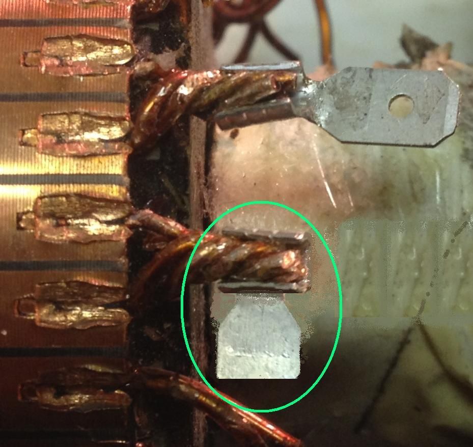
. Pair 3 and Pair 13 shorted. I took necessary care to avoid this situation by keeping the poly paper sheet that the professional winders keep. I kept on checking the poles till I completed ten pairs winding. Till then it was very much alright.

              Later my focus moved to the quantity of wire available as I understood I was running short of coil. Ignored to check the continuity. But till that time Pair3 also was normal Kogs. I completed 13 pairs last night, ran out of wire. This afternoon I wound the balance two and then remembered that i didn't check continuity from pair 11. At that time I started checking form pair 1. I found pair 3 and pair 13 shorted with the body. This bloody metallic armature cores turned out to be a big demon, to fight with, before getting the angel in.

              When I make the UFO machine from scratch, I'll see that the core will be either fiber, teflon or at least wood

              But this is an opportunity now to keep the pair orientation in correct order (cw and ccw) as UFO designed.

              And Kogs, regarding the pair resistance, I too read what UFO was telling. He didn't look into the internal res. Then how come to go ahead with the resistance? In fact this time I took care that res per pair maintained at 2 ohms incl internal res of .4 ohms. Now what should I do? Shall I reduce the wire length so that I get only 1 ohm incl meter resistance? How do we know the internal res of UFO's ohm meter? I got two meters, both are showing two different internal res

              Earlier when I tried feeding the 230v 4 amps rated currant into the rewound motor (of course I wrongly rewound, but even then I maintained the number of turns, gauge etc as manufacturer did ), i found smoke from the rotor. I stopped feeding that voltage and currant to armature. This time I increased the wire length ( and thus the no. of turns) and also the res. hoping that I could run it on 230 v 4 amp.

              Now what should I do Kogs? Shall I go ahead or shall I reduce the length in such a way it comes to 1 ohm including the internal res of meter?


              Thanks and regards
              Kumar

              on his way to pharmacy to get band-aid
              (copycat to Kogs in these expressions)
              Kogs, my son is asking me to keep your gear wheels( that you keep at the end of your posting before posting your mood) into my posts as well

              Comment


              • Hi Kogs,

                I tried editing the earlier post twice. but don't know why. it's not taking.

                I just recollected what UFO said

                Kumar,

                Just finish the two pairs left...


                Means, I need not think too much of it

                So going ahead rewinding the same way. but with some more extra paper in order not to short 25 SWG - 18 mts - nearly 2 ohm res as meter reads.

                Once again thanks a lot Kogs for the support.

                Regards and Namaste

                Kumar

                Comment


                • Nice winding Zara

                  Originally posted by Zara View Post
                  Asymmetrical 10 Pole Motor Video. Still figuring out how to get the video to play on the page.


                  ^ This is the new link to the video that now works...

                  [IMG][/IMG]

                  This is all I used to power the motor...
                  Hello Zara,

                  Nice work!...very torquey with an 18V?(I don't know, just guessing) drill battery that normally drives a 550 body motor way much smaller than your P10

                  And very neat winding work, that red spiral looks awesome!

                  On the video and this site...You will never get video to play directly here...as this site does not have the Embedding Format for You Tube on the editor, so, you did it just fine, like everybody else do it.


                  Thanks for sharing!


                  Regards


                  Ufopolitics
                  Last edited by Ufopolitics; 01-28-2014, 12:06 AM.
                  Principles for the Development of a Complete Mind: Study the science of art. Study the art of science. Develop your senses- especially learn how to see. Realize that everything connects to everything else.― Leonardo da Vinci

                  Comment


                  • Hey Machine

                    Originally posted by machinealive View Post
                    UFO
                    I just had my whole post typed and I got kicked.
                    Hey Machine,

                    Don't worry, this things start happening as we grow older...

                    And never think I ignored you or did not see your post...am old, but not that old......It is just that your post had so much info...I did not wanted to answer too fast, making mistakes...or missing right answers...

                    Ufo, if you ever wanted to sell some of you carts let me know, or even consider selling copies of your molds, to body guys so they can sell to local golf courses, seems like a good idea.
                    Seems like an excellent idea!...At one point, I was thinking about selling the whole thing, including this Yellow Pearl Model after I run the required tests with the Imperial Asymmetric Motor...and put it all on video...of course, I would sell it with the original 4.75 HP GE New Motor...

                    The sprocket that mounts to differential axle splines and to motor has to be made from scratch...and I am not a professional lathe guy...besides my lathe is just a toy. On top of that, the way GE Motor mounts to differential housing is made exactly to fit into rim...not with Imperial end, not same at all...in other words...a "project"...and right now I do not have the time or the budget to go for it.

                    About the Molds...you know that by having one set...all you need is to create a very well reinforced "Positive Mold" (which is just like the cart looks like) of all parts, with all the sealed holes and flares to brake out loose parts...from that positive or plot, then We can build as many molds as we need...

                    Let me know if there is someone interested...I will even train their guys to build it faster and smoother.*

                    What I installed on all my fiberglass molds is air fittings in the harder areas to pop out...then inject pressure when is ready to take them out...with a "spider hose" connected to all fittings and a valve to open/close, then air is injected in all fittings in one shot at @100 psi.

                    Some metal brackets to be bolted to frame and body tubing (Windshield and rear Roll Bar) have to bend and welded together by hand)...as also hood and deck lid hinges are also custom made.

                    Anyway, here was a little vid I made of my progress.

                    Induction motor progress - YouTube
                    Machine great video!...great mess too...

                    Looks awesome,but I'll be honest...I do not have the slightest idea what are U doing there!

                    First part of video, I see two phase sine waves...coming from what arrangement?...The Torpedo?...are you running Torpedo in two ways...as motor and as generator?...meaning the Toroid end?...what are the other two motor shaped cylinders?...I was guessing to be the motor(s) running toroid generator.

                    Then, second part I see Erfinder's similar wave...guessing there you are turning toroid as a motor...pulsing it with a hall?...or through Quadpulsers?

                    And by the way...I have a pretty good (I could call it awesome...lol) idea of Magnets "3D Volume and Toroid Shaped Coils......I know you are going to like it...I will make drawings some time.

                    On a last note related to your Toroid development...

                    I really believe that you should open a Thread related just to this development...for sake of having it all in one place...all organized and not splattered all around different threads...where you have been displaying material all over...what a mess... (joking)...but seriously...a separate Thread with all your videos and diagrams...along with the Tesla patents cited...would be just wonderful my friend.'

                    I will help you to make any CAD's Diagrams or 3D Rendering you need... ...at "an extra charge"... of course...

                    So, UFO, we have to decide for sure on a plan, before I get a quote. take you're time, and think of everything. Will the magnets be heavier, or the coils, which do we spin, I am still envisioning the middle section to be easier to spin, I would like to see how brush plates fit, or did you guys get the tronics done for brushless? what if we glued magnets to outside of imperial housing(double up), then make outer rotor to fit. We could replace the mags with rare earth. Just saying, there's so many options.
                    Now, You are talking about the Dual Rotor Asymmetric ok...

                    I was thinking of building the Final Dual Imperial not with magnets...but with wound stators (less magnetic friction)...Plus, we could "Quad" pulse control each Interacting coils (Two from Rotor , Inner-Outer and One from Stator simultaneously in the sequential 1.2.3 & 4... Just like the way Cornboy is gonna run his MAG3...but we are doing it with Outer Rotors extension...

                    Remember, we could collect Radiant out of each Pulsed Stator at different times (when they are off) and just add them up to a "Total Recall" Time...

                    But your idea of Inner-Outer PM glued to frame is also great!...However, using same Imperial housing...I think is not a good idea...first, because it is too thick, too heavy and made out of steel...which will cause to weaken magnetic bound on the Inner poles facing steel...this will end in affecting strength of outer fields...and second...remember we would have to take off the standing plate...no big deal...but still would have to spin it and rectify roundness in a big lathe, big chuck...So, I rather use an aluminum tubing, same ID, but much thinner than Imperial housing wall.

                    And Machine...related to "who do we spin?"...

                    The Dual Rotor Outer Assembly will deliver a super duty heavier diameter spin...as also a very solid flywheel effect...The Momentum on each Firing set will deliver a very strong "hammering effect"...and if we set them in order to get assisted by gravity...oh well...

                    Spinning the Permanent Magnets or Stators will bring some radical and difficult changes...remember Stators must spin with Brushes... ...plus all the centered brackets to hold stator housing to bearings...

                    We have a lump of marble to create something with. If any one else is going to want to get in on this, the most expensive part of waterjet is setup, they get cheaper as you buy more. Just a heads up.

                    later

                    machine
                    Yes we do have a lump of marble to create something excellent...and beautiful.


                    Kind Regards Friend


                    Ufopolitics
                    Last edited by Ufopolitics; 01-28-2014, 01:49 AM.
                    Principles for the Development of a Complete Mind: Study the science of art. Study the art of science. Develop your senses- especially learn how to see. Realize that everything connects to everything else.― Leonardo da Vinci

                    Comment


                    • Hello UFO

                      You know, your suped up carts, I think Midas is right and your product is something that would be much desirable in Asia. I will ask a few guys I know, who own there own shops. Who knows!

                      So, how do you start a thread!
                      I really don't have time to write ( like that), people have lots of questions, and that takes even more time. I couldn't write something that hasn't already been written. But I'll think about it. I have all my notes, somewhere.

                      In terms of how to build, I was just tossing ideas. It is not going to be an easy build. It seems like an easier design for a generator, I want to see how you picture it fitting together, to spin, with end plates, etc. take your time.

                      I'm going to try turning some plates for my big gen ring tomorrow. I'll just keep working away at that until your ready with your ideas. Or are you all done now?

                      Btw, El torpedo, , works better now, had the DC input, reversed. I finished hooking everything up, had a broken wire, will get to play with that a little bit tomorrow I hope. Lots of little things to do and test with that, .

                      Comment


                      • Originally posted by machinealive View Post
                        Hey kogs

                        The motors I wound last, had 25 turns of 20.5 ga. I think each coil was like
                        1 - 1.2 ohms.

                        Midas it will be interesting to see imperials testing results.

                        Machine
                        G'day Machine. UFO, Midas, Light, et al
                        Over the past few days using AWG18 I have wound 20 Pairs 15 turns per Pole on my first Imperial P56 so far. I measured the Ohms with my DMM and the reading of the DEMM was o.7 Ohms for 19 pairs #4 was reading only 6Ohms as it only reads to one decimal place there probably only 0.001 Ohms difference . Tomorrow I will finish the last 8 Pairs It takes me about 45 minutes to wind each Pair When I finish I will post some Pics.

                        @ UFO I am glad I took notice of what you said in your posting to me and also in your Video I really have watched your Video many times but really I learned from yours and others experience You mentioned that you wound 14 turns and probably after finishing winding some time back you said you might have been able to do 15. So I tried 15

                        When I finish I will try to get the 4 motors I have finished winding Varnished and balanced Please what speed do I need to get the Imperial balanced to
                        Kindest Regards

                        Kogs getting closer

                        Comment


                        • G'day Kumar
                          can't wait to see it finished
                          It Takes time for everything to come together You will gain experience when you do each motor.
                          Kindest regards to you and your son

                          Kogs always glad to help

                          Comment


                          • Batteries

                            Hi Kogs,

                            Namaste. Thanks for the kind words and encouragement. About to finish the winding Kogs. Couldn't complete before evening. Sitting now on the winding job only. Will complete by tomorrow.

                            Kogs, I ordered for 12 v 30 amp batteries 3 numbers about 10 days ago. As I was not well, I couldn't pick them up. I will pick them tomorrow once I'm done with the winding.

                            Is this battery configuration OK for our requirements at this juncture or shall I need something else ? If it needs to be changed, I can do it before I take the delivery of them. If it is OK, then I will pick them up straight.

                            And I also need to make the circuit. Before that need to complete the stator coil winding also. Lot of work is in pending Kogs. Need to complete earliest, at least by day after tomorrow.

                            Seems to be occupied whole day through, but everything is in pending.

                            Rotor winding (progressing), stator winding (yet to be done), Circuit (yet to be done). What is left in making this machine

                            And I read UFO mentioning about the resistance

                            Question by mikec_ut (post number 6061

                            Can you connect a battery directly to brushes and stator or does it only work if pulsed?

                            and UFO's answer to it (post 6062)

                            Related to feeding, it works anyway you want, however, if you used only 1 ohm resistance at stator...it will get very hot at DC straight/linear feed, normally if it is intended to be utilized this way, then much higher resistance should be wound on core, depending on Voltage to be applied.
                            I built it with lower ohms in order to pulse it and obtain radiant through reverse mode with diodes

                            here is the link to the post
                            http://www.energeticforum.com/renewa...tml#post248592

                            I got the answer why my earlier built burnt out

                            I fed it linear and the res was not even .5 ohms

                            WIll post the progress again Kogs. Meanwhile if you visit the thread, please try answering my question about battery config.

                            Regards and Namaste

                            Kumar

                            Comment


                            • Originally posted by ajaya999 View Post
                              Hi Kogs,

                              Kogs, I ordered for 12 v 30 amp batteries 3 numbers about 10 days ago. As I was not well, I couldn't pick them up. I will pick them tomorrow once I'm done with the winding.

                              Is this battery configuration OK for our requirements at this juncture or shall I need something else ? If it needs to be changed, I can do it before I take the delivery of them. If it is OK, then I will pick them up straight.

                              Regards and Namaste

                              Kumar
                              G'day Kumar

                              If you want to encourage your son to fish in the local lake you would not buy a BIG game Rod and if you wanted to catch a Marlin you would not buy a small toy rod for yourself.

                              For the battery size it is essential to match the size of battery to the job required so the battery size at the moment all that is required is a battery that has the required Volts and ah needed to test the motor at this time.
                              UFO used a small 36v Lipo battery to test his motors with.

                              I also have 3 car batteries connected in series that I can do extended tests with, I also purchased 3 small 12v 7.5ah batteries and connected them together so I could select either 12v, 24v and 36v in series with an amp meter so I could read the amps I am drawing.
                              So Pick up the batteries you have ordered they will be good for what you want at this moment.

                              Kindest Regards

                              Kogs still winding also

                              Comment


                              • 16pole, 4 magnet case

                                Hi UFO and All, I followed this thread from the beginning.(Excellent by the way).
                                But I did miss a few things here and there.
                                I 'm looking to wind a 16 pole , since I want a lot of torque .
                                I'm sure I seen this here , but after re-reading many pages I haven't found it.
                                Found the perfect motor that you can fit 2 com's without modifying the housing.
                                Just not sure of the winding pattern ,or connections.
                                If you have the time , it will be appreciated.
                                Keep up the great work, it's well appreciated.
                                artv

                                Comment

                                Working...
                                X