 Tweet
Tweet
Tesla Armature Cores...
Nkola Tesla Cores Laminations Design...
[IMG]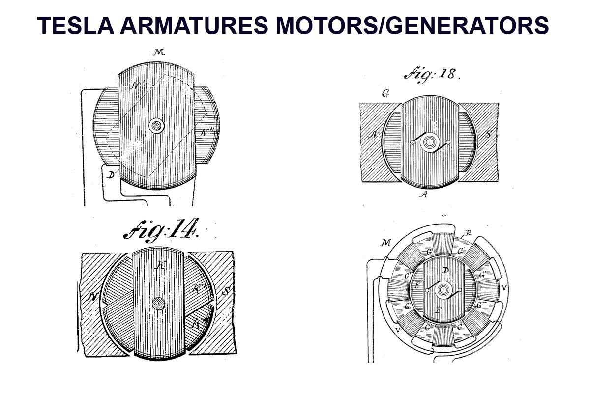 [/IMG]
Did You ever found something "different" to the way Nikola Tesla wound/displayed, His Coils in most of Designs, except for the "Toroidal Type" ?
They seem to look like a "Thick Ball" of wires...
Such difference from the way any motor or generator we know...always caught my attention...Then I started to make a Study of How the Laminations or the Structures could look like...as why?...looking for any advantages to the types we use.
[IMG]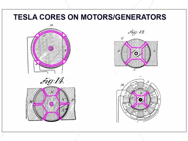 [/IMG]
I took some of them into CAD...and came up with the following:
[IMG]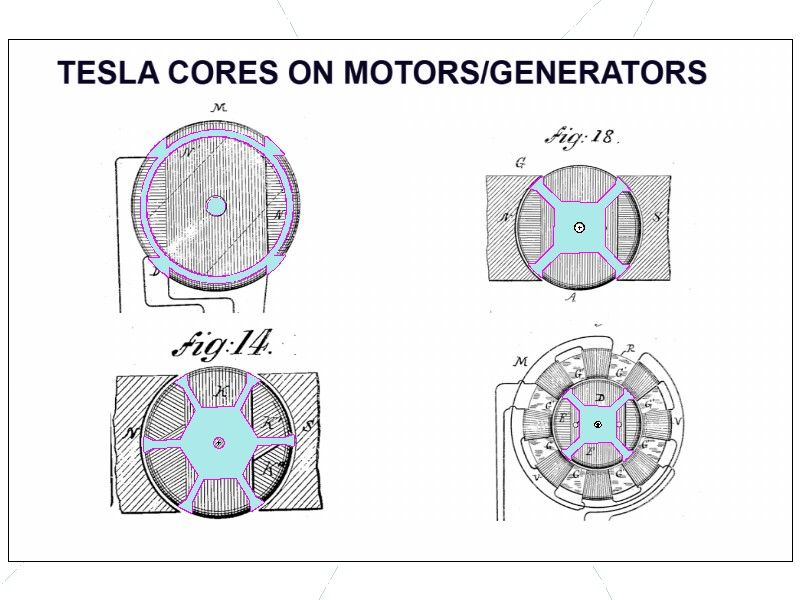 [/IMG]
On the Upper left, it refers to the Outer Static Coils of His "Disc Induction Motor"...however...same design...
On the Upper Right is about the Armature of a Two Pole Generator...same thing.
On the lower Left (FIG 14) is about a Three Phase Generator (60� apart)
And finally, on the Right Lower is about a Motor with Static Wound Toroidal Shape static Coils...while the wound Armature displays same configurations...
Conclusion followed...
Nikola Tesla utilized a "Radial" Wound Coils Geometry...where wires travel from one end to other end of the total Armature Diameter.
We utilize "Axial" Wound Coils in most of all our Electrodynamic Machines...where Coils are wound in the Outer Periphery of the Armature Structure.
[IMG]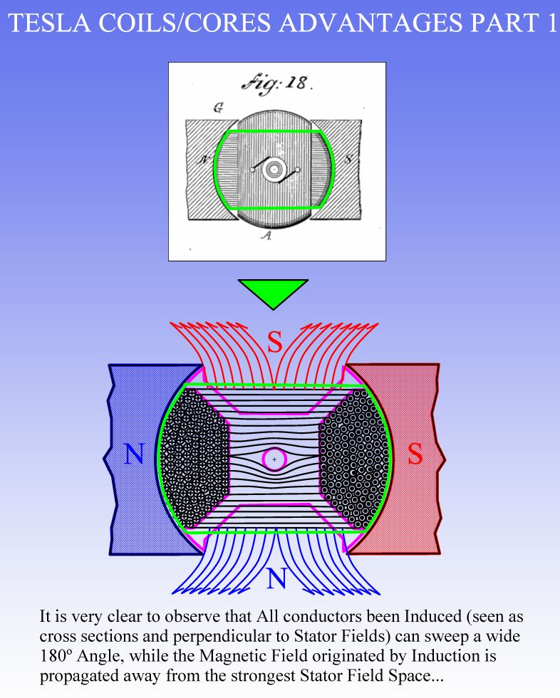 [/IMG]
Above is a Diagram of the simple Tesla Two Pole Generator, and...analyzing and showing at bottom Fig, only the Coil that is at "Induction Timing" (contoured in green on both pictures) ...or crossing the two Stators Magnetic Lines of force, it is seating exactly at 90� or "half sweep" between fields.
This type of Winding and Coil Geometry expands a very robust and directional magnetic field whenever energized as a motor or as Induction in Generator concepts...but looking at its projection is expanded outside stators field reach, or at least in other sweep angles in a very minimal percentage.
[IMG]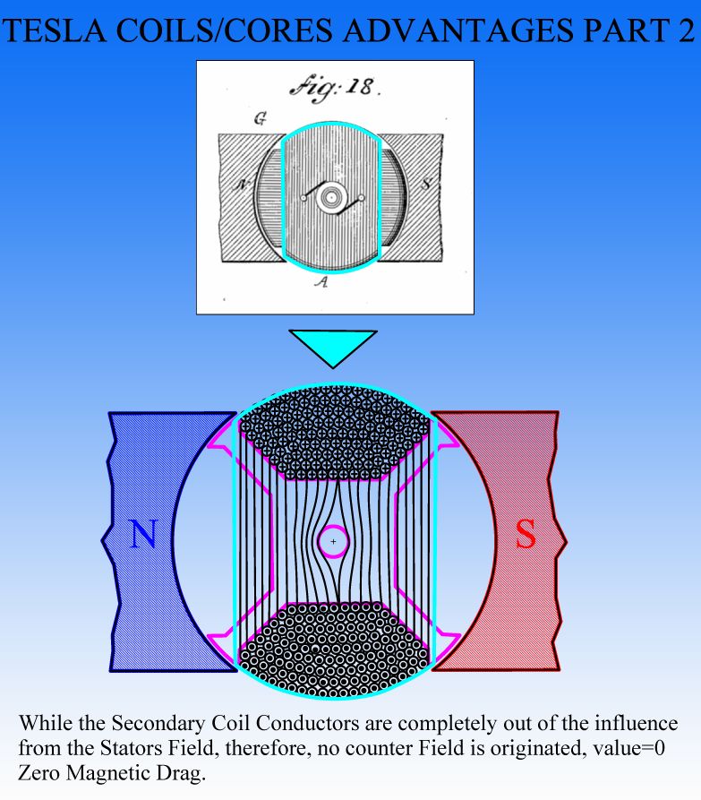 [/IMG]
On the above Image...I am just showing (Contoured in Teal Blue)...the Coil that is at "Idling" stage...all its vertical conductors are out of the Stators Field reach...
All this sequences need to be broken down in steps with degrees of rotation, in order to see the result better...or in an Animated 3D CAD Video...
The dragging or counter forces...or Lenz Effect...on this type of winding configuration is much less by far...than a Typical Axial type we all know...plus adding the fact that Tesla utilized all his Coils with Independent or Open Circuits.
And when applied to Motors...the Forces of this Type of Coils are Greater and Stronger... since they project "Face to Face" on straight line...the Interacting Fields with Stators...or, whenever utilized as Induction Machines...the Attraction to the center Rotor or Disc "D" on Tesla's Pancake Motor are much bigger than a typical closed, axial type Symmetrical AC Machine...
Warm Regards and Light to All
Ufopolitics
Nkola Tesla Cores Laminations Design...
[IMG]
 [/IMG]
Did You ever found something "different" to the way Nikola Tesla wound/displayed, His Coils in most of Designs, except for the "Toroidal Type" ?
They seem to look like a "Thick Ball" of wires...
Such difference from the way any motor or generator we know...always caught my attention...Then I started to make a Study of How the Laminations or the Structures could look like...as why?...looking for any advantages to the types we use.
[IMG]
 [/IMG]
I took some of them into CAD...and came up with the following:
[IMG]
 [/IMG]
On the Upper left, it refers to the Outer Static Coils of His "Disc Induction Motor"...however...same design...
On the Upper Right is about the Armature of a Two Pole Generator...same thing.
On the lower Left (FIG 14) is about a Three Phase Generator (60� apart)
And finally, on the Right Lower is about a Motor with Static Wound Toroidal Shape static Coils...while the wound Armature displays same configurations...
Conclusion followed...
Nikola Tesla utilized a "Radial" Wound Coils Geometry...where wires travel from one end to other end of the total Armature Diameter.
We utilize "Axial" Wound Coils in most of all our Electrodynamic Machines...where Coils are wound in the Outer Periphery of the Armature Structure.
[IMG]
 [/IMG]
Above is a Diagram of the simple Tesla Two Pole Generator, and...analyzing and showing at bottom Fig, only the Coil that is at "Induction Timing" (contoured in green on both pictures) ...or crossing the two Stators Magnetic Lines of force, it is seating exactly at 90� or "half sweep" between fields.
This type of Winding and Coil Geometry expands a very robust and directional magnetic field whenever energized as a motor or as Induction in Generator concepts...but looking at its projection is expanded outside stators field reach, or at least in other sweep angles in a very minimal percentage.
[IMG]
 [/IMG]
On the above Image...I am just showing (Contoured in Teal Blue)...the Coil that is at "Idling" stage...all its vertical conductors are out of the Stators Field reach...
All this sequences need to be broken down in steps with degrees of rotation, in order to see the result better...or in an Animated 3D CAD Video...
The dragging or counter forces...or Lenz Effect...on this type of winding configuration is much less by far...than a Typical Axial type we all know...plus adding the fact that Tesla utilized all his Coils with Independent or Open Circuits.
And when applied to Motors...the Forces of this Type of Coils are Greater and Stronger... since they project "Face to Face" on straight line...the Interacting Fields with Stators...or, whenever utilized as Induction Machines...the Attraction to the center Rotor or Disc "D" on Tesla's Pancake Motor are much bigger than a typical closed, axial type Symmetrical AC Machine...
Warm Regards and Light to All
Ufopolitics


 .
.
Comment