 Tweet
Tweet
Hello Glen
Hello Glen,
Well...I did not forget about your 33 Poles Imperial...
[IMG]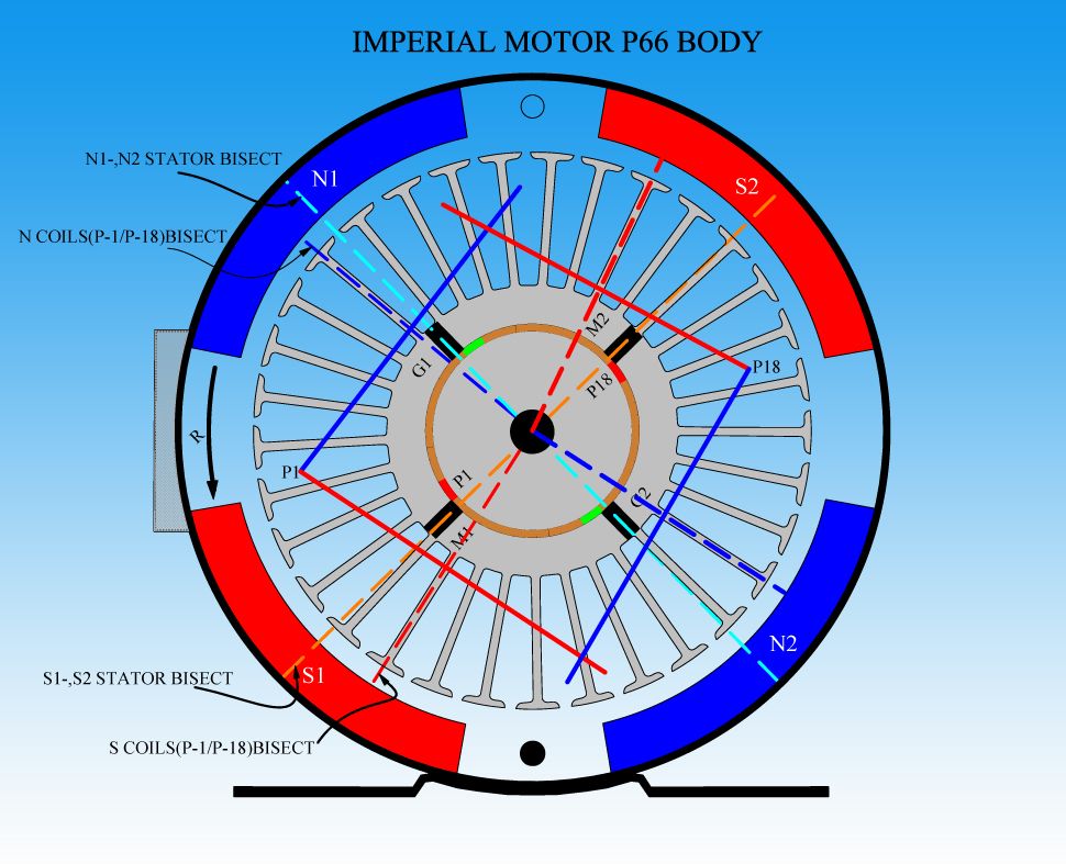 [/IMG]
What I have found out...is that there is a "Repetitive" Specific Sequencing-or may I call it an arrangement- for all Odd Number of Poles...or not divisible by Four.
So far this is the second Model that I do on this type of Machines.
The First one was a 21 Poles:
[IMG]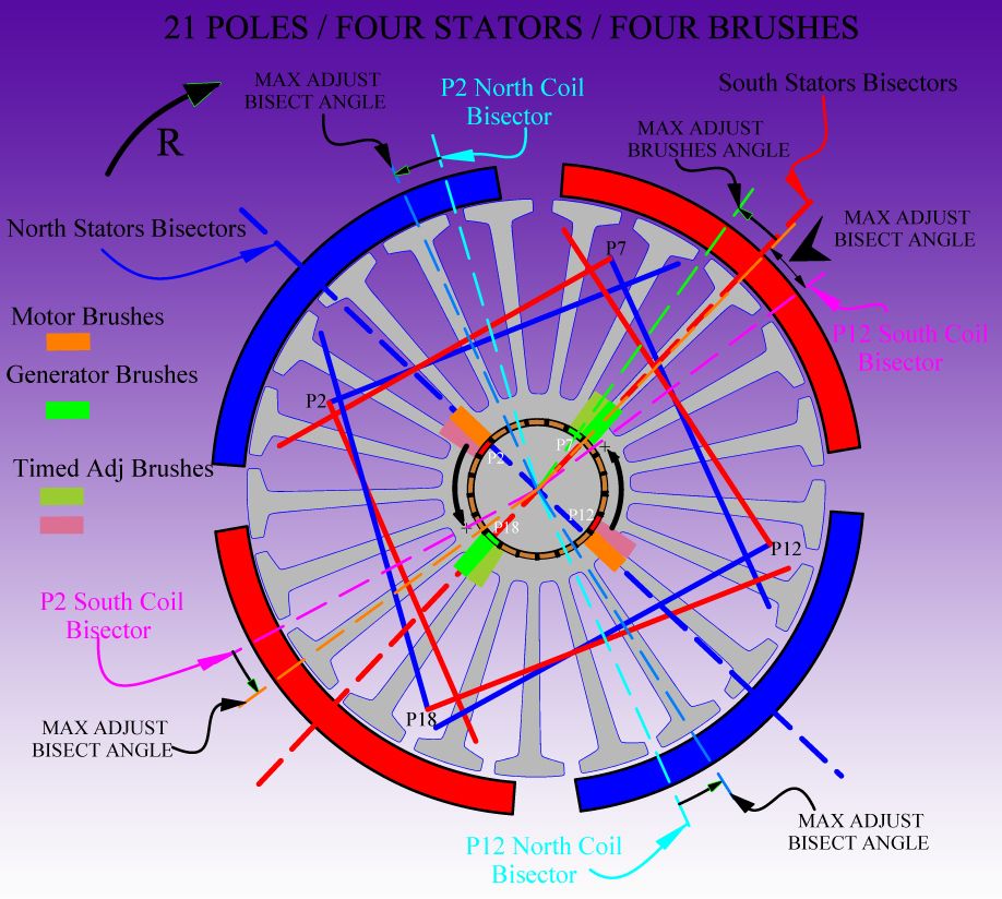 [/IMG]
And...I do not want to create confusion here...but if you notice...the way to design/lay out opposed Pairs is exactly the same way in 21 as it is on your 33 poles. And I mean the way they "intersect" in asymmetry on one side with two poles while at opposite end they cross with one pole.
In your Imperial P1 and P18 are the Motoring Pairs being fired, note above how they cross over two poles...while in the opposite/lower end they cross with only one pole...right?
So now take a look at the P21 Diagram...and follow P2 and P12 (Motoring Coils)...they cross above in two poles...and at bottom/opposite end with just one pole...(just like yours)
I just wanted to bring this interesting common attribute...that could lead us to solve a method to wind Asymmetrically, Odd Number of Poles Machines...
The Main Issue when designing a Motor...is to consider the same number of Poles per Coils (in order to keep same magnetic fields 3D Volume)...so, in your case you will be winding/grabbing Nine(9) Poles Coils...or 18 in the Pair....therefore your Coil Magnetic Bisector (Coil Center) would be the Fifth (5th) Pole...that would be your "needle" to guide you when setting the right timing.
You just have to be careful when setting timing, because the opposed Pairs Bisectors are NOT set straight at 180� apart, like in a typical "even"number of poles occur...while your Stators Bisectors are set at 180� apart.
Any questions let me know.
Warm Regards
Ufopolitics
Originally posted by GlenWV
View Post
Hello Glen,
Well...I did not forget about your 33 Poles Imperial...
[IMG]
 [/IMG]
What I have found out...is that there is a "Repetitive" Specific Sequencing-or may I call it an arrangement- for all Odd Number of Poles...or not divisible by Four.
So far this is the second Model that I do on this type of Machines.
The First one was a 21 Poles:
[IMG]
 [/IMG]
And...I do not want to create confusion here...but if you notice...the way to design/lay out opposed Pairs is exactly the same way in 21 as it is on your 33 poles. And I mean the way they "intersect" in asymmetry on one side with two poles while at opposite end they cross with one pole.
In your Imperial P1 and P18 are the Motoring Pairs being fired, note above how they cross over two poles...while in the opposite/lower end they cross with only one pole...right?
So now take a look at the P21 Diagram...and follow P2 and P12 (Motoring Coils)...they cross above in two poles...and at bottom/opposite end with just one pole...(just like yours)
I just wanted to bring this interesting common attribute...that could lead us to solve a method to wind Asymmetrically, Odd Number of Poles Machines...
The Main Issue when designing a Motor...is to consider the same number of Poles per Coils (in order to keep same magnetic fields 3D Volume)...so, in your case you will be winding/grabbing Nine(9) Poles Coils...or 18 in the Pair....therefore your Coil Magnetic Bisector (Coil Center) would be the Fifth (5th) Pole...that would be your "needle" to guide you when setting the right timing.
You just have to be careful when setting timing, because the opposed Pairs Bisectors are NOT set straight at 180� apart, like in a typical "even"number of poles occur...while your Stators Bisectors are set at 180� apart.
Any questions let me know.
Warm Regards
Ufopolitics


Comment