Announcement

Collapse
No announcement yet.

My Asymmetric Electrodynamic Machines

Collapse
X
 
  • Filter
  • Time
  • Show
Clear All
new posts

  • UFO


    I'm using high powered lipo pack around 132volts @ 16amps. I need the high voltage to handle the competition. They have 200hp and over 250lbs of torque with the champions of champions driving! We need to push our motors to its limit. I know the motor will spin a lot faster than 9000rpms with the high voltage. I just need the motor to spin to high rpms as quick as possible. I will target the max rpms to 9000. I think I will go with the 1:4 gearing ratio..... Sorry that's 4:1ratio!


    The motorcycle engineer, Tajima is thinking about designing an aluminum casing and stronger magnets for the motor. His business slows down during winter season. He will have time to build Radiance and a MotoGP 3 racer for the spring.


    Midaz
    Last edited by Midaztouch; 10-06-2013, 06:06 AM. Reason: Mistake for ratio ....4:1 is correct

    Comment


    • Midaz...

      Originally posted by Midaztouch View Post
      UFO


      I'm using high powered lipo pack around 132volts @ 16amps. I need the high voltage to handle the competition. They have 200hp and over 250lbs of torque with the champions of champions driving! We need to push our motors to its limit. I know the motor will spin a lot faster than 9000rpms with the high voltage. I just need the motor to spin to high rpms as quick as possible. I will target the max rpms to 9000. I think I will go with the 1:4 gearing ratio.
      Midaz, something does not match there in the Battery pack V-A (132V/16A)...Where I see 16 A as too low for that voltage in LiPo's ratio...maybe am wrong. However, If your Imperial will take 16 A or close to...because of the Quadpulser...it is NOT recommended to use same or around Amps amount...meaning, there must always be a higher Amp Source than Amp draw.

      But anyways, there are lots of testing you must do...so you will find out.


      The motorcycle engineer, Tajima is thinking about designing an aluminum casing and stronger magnets for the motor. His business slows down during winter season. He will have time to build Radiance and a MotoGP 3 racer for the spring.


      Midaz
      That's great, remember that the closer stators are to each others, the higher the overall performance as Speed and Torque...plus using Aluminum casing will definitively enhance the Magnetic Fields.

      If He could find Neodymium (rare earth) Magnets would be awesome...as they would be much thinner than ceramics, yet, stronger...therefore much lighter...


      Regards


      Ufopolitics
      Principles for the Development of a Complete Mind: Study the science of art. Study the art of science. Develop your senses- especially learn how to see. Realize that everything connects to everything else.― Leonardo da Vinci

      Comment


      • Midaz
        The voltage you are talking about is not necessary as at 9000 RPM at motor at 4:1 gear ratio will give a speed of 281 MPH. At 5000 RPM you will be at 160 for the straight and average speed for the last winners were 104 I read. Putting someone on a bike at 281 MPH is two times the speed needed.
        Dana
        "Today's scientist have substituted mathematics for experiments and they wander off through equation after equation and eventually build a structure which has no relation to reality."
        Nikola Tesla

        Comment


        • The problem is the shaft

          Originally posted by prochiro View Post
          Midaz
          The voltage you are talking about is not necessary as at 9000 RPM at motor at 4:1 gear ratio will give a speed of 281 MPH. At 5000 RPM you will be at 160 for the straight and average speed for the last winners were 104 I read. Putting someone on a bike at 281 MPH is two times the speed needed.
          Dana
          Dana

          Tajima and I were talking about the way to reduce the stress on the motor shaft. Yes, the motor will spin faster but it will reduce the stress on the shaft. He has been racing of over 50 years! He said he can build the shaft up some but it the weakest and most worked point for our motor. Once our motor has a dyno, he can calculate the stress measurement. Also we have to add in wind resistance. So the ratio might be higher. Our rider will have to have specific training for throttle control to reach peak performance

          Our shaft is thinner than a 250cc motorcycle. High speed, jumps and heavy bumps will stress the shaft. For light cars, heavy lead acid bikes and racing, Tajima is worried about the stress on our motor shaft. He ordered heavy duty angled dual bearings that are 3.5mm wider for the front bearing. He lathed the front bearing housing last night. Perfect fit. I will leave the gearing ratio decision up to Tajima and his team.

          Let's wait and see for the gearing ratio after the dyno.

          Midaz

          1:4 ratio!? Sorry, that's 4:1 ratio....
          Last edited by Midaztouch; 10-06-2013, 04:24 AM. Reason: Mistake

          Comment


          • Winding assymetric motors with mulitfilar twisted wire.

            Hey UFO, just going over the details, got some grey areas, pulling together a couple of your posts. Let me know if I got anything wrong.

            Originally posted by Ufopolitics post #5522 View Post
            Hello Sam,

            What I will like you to try...is what I have written in some posts above...or using a few strands of finer wire attached/ litz together...they could be...26...or 32...just wind a Coil on Armature considering size and room...then measure its resistance with the number of single strands utilized...

            ...This will result in Multi-Filar Coils....This will enhance/amplify Your Magnetic Fields for both Energies...

            ...You could play with # of strands and Gauge awg of Strands to reduce or add resistance, since the distance(length) would be the same for all coils...more alternatives here right?

            Warm Regards Friend

            Ufopolitics
            OK Ufo now ya went did it. Here I am never duping out the radiant energy capture from the coil at the beginning of the my-motors thread, never even getting the spec down for winding that coil, never building the simpler circuit to drive, just jumping right into a Monster circuit, and NOW you want me to wind a bi or trifilar thigamagigee N. Tesla invention, INTO one of his other inventions, asym motor? OK you are blowing my mind but OK I think I get it. . So you meant right here is where you introduced the idea, in the same post where you were talking about the dual rotor and tearing apart a Tamiya BLDC, no help there for the task at hand but you found something else very interesting.

            Originally posted by Ufopolitics Post #5492 View Post

            Also, there was a very interesting detail in the construction of that Motor...that I wanted to share then later discuss...

            I first noticed this type of Coil Winding in My 5000 Watts E-Bike Hub BLDC Motor when I took it apart...

            Both of this Motors were wound with Multiple Strands of pretty fine wires, twisted, configuring a "Cable Like" design...meaning, a "Multi-Filar Parallel" Coil.

            We all know the excellent Properties that comes with this type of winding that Nikola Tesla first patented in the late 1800's...and for those that have followed me since the first Thread...know that the Bifilar and Multi Filar Type of Static Coils in Parallel Connection, will enhance greatly the Magnetic Field Output of both Energies...Hot and Radiant...plus, they can handle great amounts of Amps without rising temperature as just one thicker Gauge Wire will do...

            Therefore, I am certain that utilizing this same type of Coil design into our future Asymmetrical Machines Windings...will deliver all this excellent "attributes" ...PLUS the ones that Symmetry can not offer, since their Coils never go to an "Off Stage", a "Brake"...when Radiant enters our flow.
            Just to make sure what you are recommending, probably to anyone who can manage it, is to use bi/tri/mulifilar windings for any and all asymm motor we may be building, correct?

            So if you noticed my Baldor rotors were jam-packed with wire. So I think that is a good baseline as of course the asym winding will do the same, and I have estimated the amount to be about 450', at 19ga. So if I go with a 5-pole winding as you have recommended, that should be about 90' min per coil for 19ga wire. And you had also recommended each coil be 2-3 ohms in the new winding. Your recommendation here still holds for a multifilar winding,correct?


            So lets get into the nature of a multifilar winding (which I have never done). So it is multiple strands of magnet wire, TWISTED into a multistranded cable? And I assume all strands are stripped of insulation at both ends and joined together there?

            So even if this stranded cable has approximately 19ga thickness, it should have more resistance than a solid wire, and I should be able to calculate it by summing the individual resistances. However if it is not 2-3 ohms per your recommendation above, I should make it so by shrinking the total thickness of the cable by going to a higher gauge there by going up to a higher gauge on the individual strands. And then the thickness of a stranded cable could also be the function the number of twists per foot also, which will increase the amount of wire and the resistance per foot too. Some people use a jig to wind multifilar wire. Clearly I might need 100+' lengths for each coil... Whew, another big job! Boy I hate that high gauge radio shack stuff. Definitely gonna start with 26ga and see how that looks. And to put it into the commutator, do you think the stranded stuff will hold?

            PS: leaning toward Dual Pentagon Y winding pattern. Looking at building a generator maybe, my motor goldmine just put another Baldor up for sale...
            Up, Up and Away

            Comment


            • Midas, Whats the Schedule?

              Great progress! Is there particular race your team is targetting? Let us know if there is a feed or video we could watch. or some race results. I can only imagine what great advantages the driver will have, not running out of torque at the top end of gear, and more in the lower end. As you have the motor built, I know it will not be long before it is mounted, and the bike running. I would be thrilled to see side by side performance numbers against a symmetric model. Your engineers have their hands full as they do not have any performance numbers for this motor... By the way quite impressed by your command of English. Can't say the same for my command of Japanese, as I spent time in Okinawa and Misawa, visiting Tokyo a couple times.

              Domo arigato for sharing.
              Last edited by sampojo; 10-06-2013, 05:12 AM.
              Up, Up and Away

              Comment


              • Rare earth metals

                Midaz, something does not match there in the Battery pack V-A (132V/16A)...Where I see 16 A as too low for that voltage in LiPo's ratio...maybe am wrong. However, If your Imperial will take 16 A or close to...because of the Quadpulser...it is NOT recommended to use same or around Amps amount...meaning, there must always be a higher Amp Source than Amp draw.

                But anyways, there are lots of testing you must do...so you will find out
                UFO

                When using the quad pulser, our amps drop into the safety zone for discharge of a 15 C-rating for lipo batteries. Basically, we can use any lipo battery safely because of the quad pulser dropping the amps. My battery choice is over 30 c-rating. I'm more than good!


                That's great, remember that the closer stators are to each others, the higher the overall performance as Speed and Torque...plus using Aluminum casing will definitively enhance the Magnetic Fields.

                If He could find Neodymium (rare earth) Magnets would be awesome...as they would be much thinner than ceramics, yet, stronger...therefore much lighter...
                His son is the leading professor for rare earth metals in Japan. It's doable but we need a major sponser.

                Midaz
                Last edited by Midaztouch; 10-06-2013, 05:29 AM.

                Comment


                • Originally posted by sampojo View Post
                  Great progress! Is there particular race your team is targetting? Let us know if there is a feed or video we could watch. or some race results. I can only imagine what great advantages the driver will have, not running out of torque at the top end of gear, and more in the lower end. As you have the motor built, I know it will not be long before it is mounted, and the bike running. I would be thrilled to see side by side performance numbers against a symmetric model. Your engineers have their hands full as they do not have any performance numbers for this motor... By the way quite impressed by your command of English. Can't say the same for my command of Japanese, as I spent time in Okinawa and Misawa, visiting Tokyo a couple times.

                  Domo arigato for sharing.
                  Sampojo

                  I'm American. My Japanese is awful!

                  I have to agree with you, Team UP and our Japanese engineers have their hands full! I'm confident that we will succeed in this transitional phase. I have two dedicated targets that must be accomplished.

                  First we must prepare one bike, "Radiance" for the TT-zero Isles man. It's the most prestigious and most televised motorcycle race on the planet. It's one race a year in June. We need to be there!

                  Secondly, we need to prepare another bike for the MotoGP 3 series. There are many races all over Japan. It's a long season. I believe we can take the championship with the right rider.

                  Everything can be done but we need a major sponsor

                  We will prepare first Radiance. Take her to a few "Fun" races at major raceways. Anyone can join those races. It's our best chance to have a major sponsor look at us. Plus green technology is big in Japan. Tajima and I think we have a good chance to get sponsors.

                  Keep it Clean and Green
                  Midaz

                  Comment


                  • Originally posted by sampojo View Post
                    Hey UFO, just going over the details, got some grey areas, pulling together a couple of your posts. Let me know if I got anything wrong.


                    OK Ufo now ya went did it. Here I am never duping out the radiant energy capture from the coil at the beginning of the my-motors thread, never even getting the spec down for winding that coil, never building the simpler circuit to drive, just jumping right into a Monster circuit, and NOW you want me to wind a bi or trifilar thigamagigee N. Tesla invention, INTO one of his other inventions, asym motor? OK you are blowing my mind but OK I think I get it. . So you meant right here is where you introduced the idea, in the same post where you were talking about the dual rotor and tearing apart a Tamiya BLDC, no help there for the task at hand but you found something else very interesting.


                    Just to make sure what you are recommending, probably to anyone who can manage it, is to use bi/tri/mulifilar windings for any and all asymm motor we may be building, correct?

                    So if you noticed my Baldor rotors were jam-packed with wire. So I think that is a good baseline as of course the asym winding will do the same, and I have estimated the amount to be about 450', at 19ga. So if I go with a 5-pole winding as you have recommended, that should be about 90' min per coil for 19ga wire. And you had also recommended each coil be 2-3 ohms in the new winding. Your recommendation here still holds for a multifilar winding,correct?


                    So lets get into the nature of a multifilar winding (which I have never done). So it is multiple strands of magnet wire, TWISTED into a multistranded cable? And I assume all strands are stripped of insulation at both ends and joined together there?

                    So even if this stranded cable has approximately 19ga thickness, it should have more resistance than a solid wire, and I should be able to calculate it by summing the individual resistances. However if it is not 2-3 ohms per your recommendation above, I should make it so by shrinking the total thickness of the cable by going to a higher gauge there by going up to a higher gauge on the individual strands. And then the thickness of a stranded cable could also be the function the number of twists per foot also, which will increase the amount of wire and the resistance per foot too. Some people use a jig to wind multifilar wire. Clearly I might need 100+' lengths for each coil... Whew, another big job! Boy I hate that high gauge radio shack stuff. Definitely gonna start with 26ga and see how that looks. And to put it into the commutator, do you think the stranded stuff will hold?

                    PS: leaning toward Dual Pentagon Y winding pattern. Looking at building a generator maybe, my motor goldmine just put another Baldor up for sale...
                    G'day Sampojo
                    To calculate the resistance of parallel coils see here
                    PARALLEL RESISTOR CALCULATOR
                    1 strand of AWG 21 = .71 mm diam. = .04489 Ohms per meter
                    1 strand of AWG 30 = .25 mm diam. = .3362 Ohms per meter
                    so
                    2 strands = .1681
                    3 strands = .11207
                    4 strands = .08405
                    5 strands = .06724

                    Not summed resitsance Go Figure

                    Probably you would need approximately 3 litzed strands of AWG 30 to compare to the AWG place of single AWG 21

                    Something to think about

                    Kindest regards


                    Kogs sometimes does some thinking

                    Comment


                    • sampojo

                      As for a gig to litz the wires, not much is needed. Place the wires you want to twist togeather along a clean (no grass and twigs) area and tie one end into a knot and onto something firm. I use the hitch on my truck. Then stretch out all wires to take out slack in each one so they are as one. Tie a knot at the other end so that end also stays together. Get one of those bolts that has a closed ring at one end and put into your drill chuck. The idea here is to pull back on the drill so as to keep the wire off the ground but not hard enough to break the wire. As you twist the wire gets shorter. Most people twist it so that there is a full turn every couple of inches. When done, keep the knots on until winding time. As you can see, you must start with a longer wire than you want as twist and waste at both ends are loss. I then read OHMs and keep cutting off wire until I have the exact ohm I want. All wires a the same. Wind motor as usual.
                      Dana
                      "Today's scientist have substituted mathematics for experiments and they wander off through equation after equation and eventually build a structure which has no relation to reality."
                      Nikola Tesla

                      Comment


                      • Wow, thanks for the help kogs, Dana

                        Dana, lol on the twigs. The road out in front of the house can be pretty quiet sometimes. But if I get it off the ground I probably got 100' from the curb to the playground in the back. This image, in my mind's eye, is hilarious, huh? Thanks, I had been wondering about just using a hand drill to do the winding... Great info: 2" per revolution. I think the magnet wire could take tighter winding, say 4 or 10 or 20 rev per inch, but still maintaining the integrity of the insulation. Wonder what that would do to performance. definitely make a high guage stranded cable thicker fast, increasing total resistance a lot, using more wire.

                        Originally posted by iankoglin View Post
                        G'day Sampojo
                        To calculate the resistance of parallel coils see here
                        PARALLEL RESISTOR CALCULATOR
                        1 strand of AWG 21 = .71 mm diam. = .04489 Ohms per meter
                        1 strand of AWG 30 = .25 mm diam. = .3362 Ohms per meter
                        so
                        2 strands = .1681
                        3 strands = .11207
                        4 strands = .08405
                        5 strands = .06724

                        Not summed resitsance Go Figure

                        Probably you would need approximately 3 litzed strands of AWG 30 to compare to the AWG place of single AWG 21

                        Something to think about
                        Kogs Are you saying 1/R=1/R1+1/R2+...+1/Rn formula you link to doesn't hold for multifilars or just that R=R1+R2+...+Rn, something I may have implied, is not right? But I can see the multifilar coil having dynamic induced resistance.

                        @Ufo: So is the multifilar inductance suspect in introducing extra and even dynamic resistance at minimal cost to the coil strength or even improving it then? So this might kick performance up? (even more radiant energy harvest?) So R= f(I,freq), by some Maxwellian non-linear equation I bet. And of course a pulsed square wave current is composed of a large number and very high frequencies. Crazy, man! If it exists, anyone have a reference? So when you said the coil strands in the BLDC motor looked like a cable, I started thinking about steel cables, and how tightly wound they are. Is this what you saw or something like Dana said, 2"per turn, (or 6 turns per foot)? I have seen bifilar coils used in the my-motors thread and I don't think they were twisted at all and the ends were not joined either? Is the twisting just a matter of handling convenience here, or a way of thickening the cable for a lower overall AWG with a higher static resistance?

                        I will run those numbers for various awg sometime soon and see what shakes out. Midas, does your racer need another edge?!?! Imperial V2!!!!
                        Last edited by sampojo; 10-06-2013, 06:03 PM.
                        Up, Up and Away

                        Comment


                        • Turion on 07-13-2012, 07:11 PM you say: "Oh, I found a place that sells A solid piece of plastic with a hole in the center. It has a solid layer of copper bonded to the outside of the plastic, so all you have to do is cut through the copper with a hack saw until you get to the plastic in different places, and then chisel away the unwanted sections of copper. It is a "universal commutator" which you can put on any size shaft by drilling out the center hole and match up with any commutator by marking and cutting the copper in the correct place. I will try to find that link and post it here.
                          Dave"

                          - hey dave, did you ever post a link to the copper coated plastic? id like to make a commutator but i couldnt find it. please post or repost the link to it and let me know. regards. -energy1
                          Last edited by energy1; 10-06-2013, 06:27 PM.

                          Comment


                          • Multifilar winding

                            1. Be careful with your cordless drill. Mine desintegrated because it was not built for pull forces. The shaft is held by a tiny spring washer only.

                            2. I feel there is no real electrical advantage if you twist multifilar wires that hard. You will end up in spending much free air between turns. Apart that you need to be aware of twist direction and later winding direction. They might interfere and make things hard to deal with. Sailors are aware of this fact and account for it if using laid ropes. If you operate your drill clockwise the result of multifilar wire is turning CCW. This product is allowed to be wound CCW only. And vice versa of course.

                            Facts shown above remain true if you turn your rope 180 degree. It will still be CCW / CW like before. For inspection take a rope in your hand like above and observe the direction of strands if departing from you. If they run to the right - CW and if they run to the left CCW.
                            The only real use of laid multifilar windings is to prevent tangling of individual wires. I recommend to insert beginning of multifilar strands through a small plastic tube or hose of about 30cm length. While winding you shift it forward step by step in order to have parallelled wires between tube and your coil, well ordered for painless hand winding .

                            Do not confuse with litz wire at HF coils. There a major concern is to reduce interwinding capacitance and space lost does not count. They additionally braid those litz windings very similar to a basket.
                            But that is not our application.
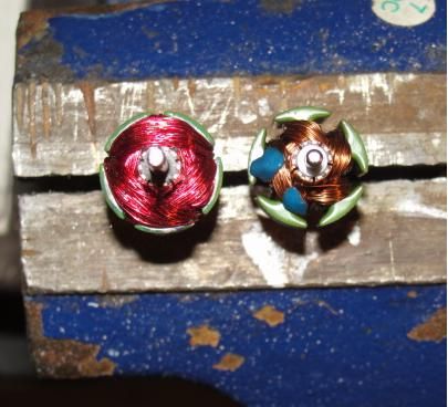
                            JS
                            Last edited by JohnStone; 10-06-2013, 07:29 PM.
                            Experts spend hours a day in order to question their doing while others stopped thinking feeling they were professionals.

                            Comment


                            • Greetings ufopolitics and everyone,

                              I'm way behind the curve here but hopefully will be able to contribute in time. My 5 pole Goldmine motors have arrived and I am anxious to start my first build. Before I do I would like to present my plan for you to look over and critique.

                              My goal for this build is for minimum amps input and maximum volts/amps output and I have chosen to wind with bifilar #32 awg and the asymmetric radio shack winding method.

                              The original total armature winding resistance is 8.2 ohms with #29 awg wire and my calculations say this is 100 ft of wire total or 20 ft and 1.64 ohms per pole, and 20 ft of #32 bifilar will give 1.641 ohms per coil pair to match.

                              Is my thinking correct about this, and are my calculations correct? Or should I do it differently, such as wind for a different resistance per coil pair?

                              Thanks and best regards,
                              Cadman

                              Comment


                              • Re: Cadman advice

                                I'll take a shot. Not sure about how those Goldmine motors are wound but the Radio shack had a lot of unused volume in the armature. Asym on the left, of course.


                                Your mission should you decide to accept is to fill all voids with copper wire!

                                So if the cross-section looks 1/4 unused increase wire length/ohms a rough amount accordingly, 20-30%. These little motors are best if you can get them over 2 ohms. Its always best to go up a bit on the gauge, but I can't recommend working with higher than 32ga. The RS original wire was 30ga.

                                Got that split coil winding down pat?

                                Happy motoring
                                Last edited by sampojo; 10-07-2013, 04:30 AM.
                                Up, Up and Away

                                Comment

                                Working...
                                X