 Tweet
Tweet
Originally posted by JohnStone
View Post
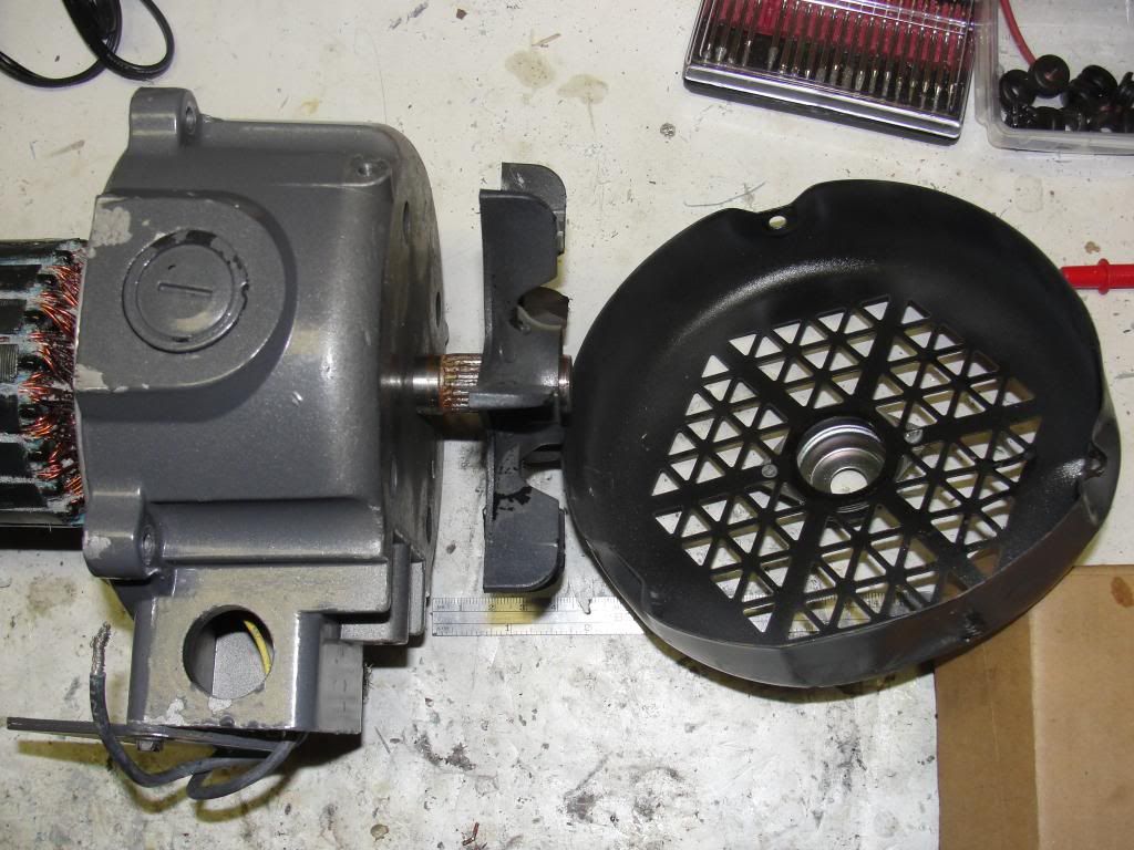
Yep on My 3 P56 motors I had to file the end plates so they would fit in to the Stator housing it took about 30 min each
Kindest Regards


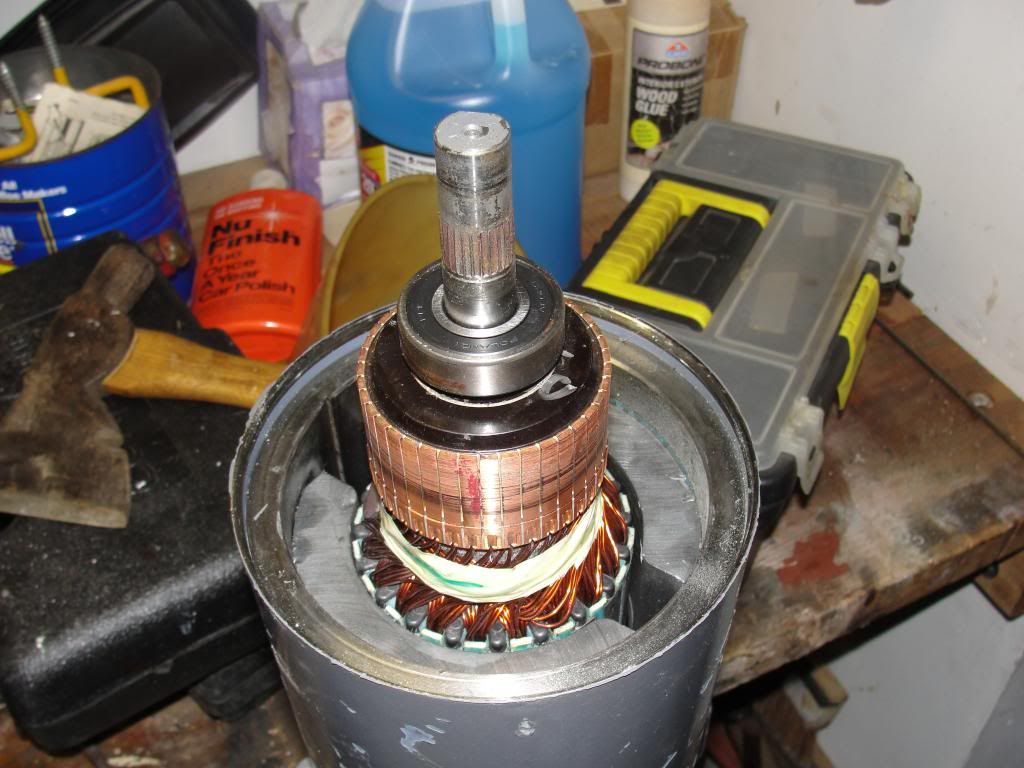
 so that I have them 2 motors ready to wind them and then we will see how they Go


Comment