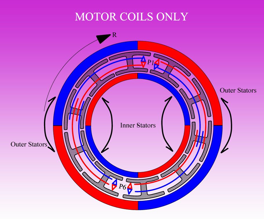
Announcement

Collapse
No announcement yet.

My Asymmetric Electrodynamic Machines

Collapse
X
 
  • Filter
  • Time
  • Show
Clear All
new posts

  • [IMG][/IMG]

    Hello UFO, this is the design i will be building next, only with electromagnet stators, and maybe a different amount of rotor coils/ stator coils. i am sure we can put our heads together on that.

    What i was reffering to in my last post, is the wasted fields, on the outer stator, and inner stator.

    I could build a Figuera drum, fixed to the rotor, to go over outer stator, and inside inner stator.

    My question was, with outer drum and inner drum only facing one/mono, field each, could we wire them such to be connected together, as if they were passing through a n/s field similtaniously, producing a sine wave that we could rectify?

    Hope this makes it clearer, Thanks Cornboy.

    Comment


    • Yes , you could do that...

      Originally posted by Cornboy 555 View Post

      Hello UFO, this is the design i will be building next, only with electromagnet stators, and maybe a different amount of rotor coils/ stator coils. i am sure we can put our heads together on that.

      What i was reffering to in my last post, is the wasted fields, on the outer stator, and inner stator.

      I could build a Figuera drum, fixed to the rotor, to go over outer stator, and inside inner stator.

      My question was, with outer drum and inner drum only facing one/mono, field each, could we wire them such to be connected together, as if they were passing through a n/s field similtaniously, producing a sine wave that we could rectify?

      Hope this makes it clearer, Thanks Cornboy.
      Cornboy,

      This was an earlier design...before I move into this latter one, based on Dual Rotors, NOT Dual Stators...remember the "H" Pattern, patented by your neighbor ...?

      And Yes, You could do a Figuera's Dual Drum here, collecting from "Other Side" of Stators...connect them in series to add both Induced/Generated energy...and you could even use some of its flow to feed rotor after take off and saturation of fields since they are within the same rotating Armature.

      But, Cornboy, this conversation and Diagrams would create confusion to others reading my previous posts...so, please, let's drop it here, since they are two completely Opposite Configurations.

      The one you are bringing on is a Dual Stators Single Rotor...while the one I am trying to start displaying from its simpler stage......is a Dual Rotors and Single Stator.

      The one you are showing is way more complex to build (you know that, since it must be build completely "from scratch")...than using an existing complete Motor and adding just some components and modifications.

      Imagine Your MAG3 Inner 36 Rotor Poles...assisted/amplified/enhanced by 72 Outer Rotor Poles, interacting with the side of your stators now sinking/wasting their magnetic field into that nice outer casing?

      But before getting there...finish the God...all mighty...MAG3 in its "Original Single Rotor State"...please.


      Thank You my Dear Friend!


      Regards


      Ufopolitics
      Last edited by Ufopolitics; 09-25-2013, 07:40 AM.
      Principles for the Development of a Complete Mind: Study the science of art. Study the art of science. Develop your senses- especially learn how to see. Realize that everything connects to everything else.― Leonardo da Vinci

      Comment


      • Refreshing Old Related Model

        Here is the "Original" Single Rotor Three Pole Asymmetric Motor...just to freshen up some required concepts...

        [IMG][/IMG]

        Regards


        Ufopolitics
        Principles for the Development of a Complete Mind: Study the science of art. Study the art of science. Develop your senses- especially learn how to see. Realize that everything connects to everything else.― Leonardo da Vinci

        Comment


        • Yep, understand UFO, and will drop it here, when you start new Scratch build thread we can discuss it.

          Just looking at it from the point of not wasting any magnetic interaction, if possible.

          Also seperate coil cores , without iron flux connection, like in a symetrical motors rotor, i feel will offer added benifits.


          Warm Regards Cornboy.
          Last edited by Cornboy 555; 09-26-2013, 01:39 AM.

          Comment


          • Nice lecture on asymmetric motors.

            I was thinking of buying a cnc mill, for engraving. They are less then $1000., which will probably be less then what I'm going to get pinched for this generator cutout. They don't recommend metal, but, even if it lasts once it paid for itself. But if it lasted longer, maybe I could cut a couple of smaller designs, like above. Does anyone know if I could cut 1/16 plates with a cnc engraver. . I'm sure it would work.

            Comment


            • Machine
              All engravers and many of the small mills can cut soft metal to a point but you will find that the HP is just not there to do anything of this size. You will go thru many bits and scrap half of your parts. Many do not have enough area movement but there are some who do. I would not try it with an engraver. The speed you must go with that setup could take several hours per part.
              Dana
              "Today's scientist have substituted mathematics for experiments and they wander off through equation after equation and eventually build a structure which has no relation to reality."
              Nikola Tesla

              Comment


              • Originally posted by machinealive View Post
                Nice lecture on asymmetric motors.

                I was thinking of buying a cnc mill, for engraving. They are less then $1000., which will probably be less then what I'm going to get pinched for this generator cutout. They don't recommend metal, but, even if it lasts once it paid for itself. But if it lasted longer, maybe I could cut a couple of smaller designs, like above. Does anyone know if I could cut 1/16 plates with a cnc engraver. . I'm sure it would work.
                Fortunately we need relatively soft iron for magentic laminations. So it might work for you. The main issue is to prevent any loss of steps from stepper motors. This will occure if you go too hard or with too big tool into the material. On the other hand if you act too reluctant the tool might smear or clog insted of cutting.
                Additionally you should have an idea on how to hold the sheet in place. Best solution is a vacuum desk. It can be DIY built easily.

                I own a CNC mill (400x500mm working area) mecanically full functioning but all electronics missing. Is there any recommandation out there how to proceed along USB I/F, controller, driver PC SW?
                Old parallel I/F is outdated this times and USB / parallel converters do not face timing requirements. Plese PM in order to get thread clean.
                JS
                Experts spend hours a day in order to question their doing while others stopped thinking feeling they were professionals.

                Comment


                • Introducing ACS712 Low Current Sensor from SparkFun and its Config using Arduino

                  Originally posted by Lightworker1 View Post
                  Hello @UFO and @All

                  Here is the follow up video:


                  https://www.dropbox.com/s/r05e3y8kwz...t%20Sensor.mp4


                  All questions are welcome.

                  Warmest regards


                  Hello @All, here is an update.

                  The video "Introducing ACS712 Low Current Sensor from SparkFun and its Config using Arduino"
                  is now also uploaded to YT.

                  On this forum, Arduino is becoming an important as controlling element.

                  Eliminating noise from the Sensor Readings on Arduino with digital filtering

                  A mode filter technique is a combination of a median filter and an averaging filter:
                  You sort the values and take the average of the ones in the middle.
                  In this case the author took the average of the 10 center values.
                  The benefit of doing this is that the output of the filter can have a 10 times
                  higher resolution than the A/D converter.
                  Furthermore no additional special libraries are necessary.

                  Introducing SparkFun ACS712 Low Current Sensor using Arduino - UFOPOLITICS Project - YouTube

                  Warmest regards

                  light


                  There are two mistakes one can make along the road to truth...not going all the way, and not starting.
                  --Prince Gautama Siddharta


                  "If we could produce electric effects of the required quality, this whole planet and the conditions of existence on it could be transformed.
                  We could irrigate arid deserts, create lakes and rivers and provide motive power in unlimited amount." Nikola Tesla, June 1919
                  **** Message Post, Says lengthen the message by 10 characters - Why ??? Must be a Bug ****

                  Comment


                  • Message all in Quotation Marks

                    Originally posted by Lightworker1 View Post
                    **** Message Post, Says lengthen the message by 10 characters - Why ??? Must be a Bug ****
                    Hello Light,

                    The message is because you are enclosing must of the message text within quote marks, then software only reads whatever is outside the marks as your actual response.

                    []
                    ...
                    [/]


                    Warm Regards


                    Ufopolitics
                    Principles for the Development of a Complete Mind: Study the science of art. Study the art of science. Develop your senses- especially learn how to see. Realize that everything connects to everything else.― Leonardo da Vinci

                    Comment


                    • Originally posted by Ufopolitics View Post
                      Hello Light,

                      The message is because you are enclosing must of the message text within quote marks, then software only reads whatever is outside the marks as your actual response.

                      [][/]


                      Warm Regards


                      Ufopolitics
                      Hello Dear Friend UFO many thanks for the clarifications

                      Warmest regards

                      light

                      Comment


                      • Thanks for tips John And Dana. I'll get a quote first, then think about next step.
                        Yesterday, someone said they had 2 old generators that they were going to throw out, same size as my Lincoln I'm modifying. Told me I could have them if I picked them up. Yep, one man's junk... .

                        Comment


                        • Reply to Ufo from post 5492 Baldor sahft length.

                          Originally posted by Ufopolitics in post 5492 View Post

                          @Sampojo: Great work!!...Those Baldors look excellent when set together for the Asymmetric build...I noticed that you could obtain a bit more shaft out...If you could Lathe/Reduce cylindrical frame height, then... Lathe an inner rim like it has now...in order that Brush Caps Assembly sits more in, allowing shaft to come out much more. However, I know the amount of work involved to do this...and expense if you have to send work to be made by a Machine Shop...
                          That is the short side. Here is the other side, it has a 1.75" shaft extension. Long enough for the business end, right? The symmetric business end had a slotted 2.25" shaft. I think the original picture of the shaft on the short side is just long enough to remount the symm motor fan, maybe.


                          So my small toy and window asym motors showed heating problems. This Baldor design is unique from what I have seen regarding how brushes are mounted. Usually brushes are mounted on a PCB type substrate. These are mounted within a heavy aluminum endcap, (electrically insulated of course) with high heat dissipation capability.


                          The brushes don't come out easy either. No luck there yet and no need to so far. As designed it is a totally sealed motor, getting cooling air blown across it on the outside, great for some pretty bad environments. I could mount the fan on one side still but not the business end though. But if you look here I think there is room for a thin fan between the bearing and comm that could blow air across comm and brushes thru the slots between the mags to a similar fan on the other side.


                          But I would have to open up some air holes on the endcaps. But even without the fans the heavy alum endcaps might mean it runs cooler than even the imperial, except it is all open. Its brushes are on a fiber substrate right?

                          @Ufo, should I break open the endcaps for air, drilling a lot of holes to admit air and think about putting in a fan? Maybe see how it runs, then go for it if it seems hot... would only need to pop off bearings to mount a new fan...

                          Here is the big question. As you may have noticed these rotors are again different with the winding. The rotor was completely stuffed with wire. I estimate about 450' on the smaller half horse rotor, at 19AWG. When you recommended higher ohms on a 5-pole design in post 5428 and going to a higher gauge, I have usually bumped it up 2AWG on my motors, but I still have had the heating probs. Am wondering heavily if I should maybe use 22AWG? Not sure if I was measuring it right but with the 19 sym wiring, I barely got just under 3 ohms there on the whole winding across all poles. You were talking 2-3 ohms per coil right? That would be a total of 15 to compare it with the sym wires. So that AWG has to go up some.

                          @UFO, whats your assessment, 22 OK? 23 maybe?

                          I have an idea on a way to calculate an approximation. Definitely take some head scratching...

                          Thanks Sam
                          Last edited by sampojo; 09-27-2013, 08:53 PM.
                          Up, Up and Away

                          Comment


                          • Ready for winding

                            @ All

                            It's been a real adventure getting the Imperial ready for winding. A lot of trials and errors BUT I'm finally ready.

                            Keep it Clean and Green
                            Midaz
                            Last edited by Midaztouch; 10-05-2013, 04:43 AM.

                            Comment


                            • Originally posted by Midaztouch View Post
                              @ All

                              It's been a real adventure getting the Imperial ready for winding. A lot of trials and errors BUT I'm finally ready.

                              Keep it Clean and Green
                              Midaz
                              Please check if its dimensions fit into stators. It might be necessary to cut a bit from outer diameter an lathe.
                              JS
                              Experts spend hours a day in order to question their doing while others stopped thinking feeling they were professionals.

                              Comment


                              • Originally posted by JohnStone View Post
                                Please check if its dimensions fit into stators. It might be necessary to cut a bit from outer diameter an lathe.
                                JS
                                JS,

                                Everything has been checked and rechecked. I believe everything is lined up and ready for winding.

                                Midaz

                                Comment

                                Working...
                                X