Announcement

Collapse
No announcement yet.

My Asymmetric Electrodynamic Machines

Collapse
X
 
  • Filter
  • Time
  • Show
Clear All
new posts

  • John Stone,
    I am sorry to hear that your wife is not doing well. You have my best wishes for a speedy recovery.
    You obviously have had a lot more time to deal with the issues of the Imperial motor than I have, and given it a lot more thought. Keep in mind that I am a student of this technology learning at the feet of every one here. You have asked a lot of questions that are fairly technical in nature but I will try my best to answer your concerns and in so doing give an outline of my plan as I do have one that is subject to change upon new information. It is said that software is never finished.
    1. variable frequency
    I am not sure why this is a problem. I think that the 2 millisecond pulses fit nicely into our target rpm range. 3600 rpm works out to 16 milliseconds per revolution divided by four gives us 2 pulse cycles per on period. I do not subscribe to the method of varying the wait period to make adjustments to load that will be handled by the duty cycle, with the exception of ramp up to speed and catastrophic load(will talk about this later)
    2. variable duty cycle
    Surely 8 bits of resolution is more than adequate for our needs.
    3. scalable 4/6 phase signals
    The uno has 6 pwm pins, and all others have more
    4. low processor load
    I can't imagine that having one pin active at a time would create any more of a load than any solution we make come up.
    5. timing
    I have thought about this for days. In a gasoline engine all timing is mechanical in nature. The distributor is adjustable to advance or retard the timing and the valve train is kept in time with chains or belts and gears. The only help that we have with a DC motor is the commutator and brush combination. That does help significantly. If you are speaking of the race that ufo was talking about that is actually very easily implemented with pauses and a loop turning on the pin pauseing and then turning off the pin, move to next pin. and repeat. then loop back through. The problems that I for see are two and there could be more.In cases of extreme load does the rotor have enough weight to give an adequate flywheel effect, or is there insufficient inertia to keep it moving and the rpms drop precipitously. If the second condition arises it is possible that the rotor would get out of sync with the program and would need to be ramped up to speed again. If out of sync could it possibly lock up. That would be a worse case scenario. I am not that familiar with the archetecture of the Imperial to know how would could be certain that the signal will always be synchronized with the motor. Like I said hopefully the brush commutator will help us here.
    While we are on the subject any attempt to enter into the clocks of the processor and come up with more control on the timing of the pulse waves as I understand will defeat the interrupts at pin 0 and 1. Whereas the pwm pins will allow the interrupts to be used without affecting their timing.
    Something that I am equally concerned about is the lack of information available to us in a timely fashion to respond quickly to downturns in rpms. I would like to respond to movements down in rpms in no more than 100 milliseconds. There would only be a count of 6 interrupts available at 3600 rpms. at 3400, 5 and then it would drop all the way to 4 at 2400 rpms. Using a hall effect sensor or an infrared emitter receiver as a tachometer with one signal per revolution would only yield these amounts. I am leaning more towards the infrared emitter receiver because I could then drill extra holes to get more signals and get fractions of a revolution.
    Can one Arduino be used?
    Like all questions of this nature it depends. I believe that one Arduino can be used for the setup that I envision. I own several and they all have usb capabilities. The problem with all serial signals is that the signal degrades with any significant distance. If you are in close proximity, 8 to 9 feet little or no degradation. 14 feet or more will depend on the quality of your wire and components and you are rolling the dice. blue tooth not much better but doesn't require wire. How elegant is your solution? How much memory will you need to implement it. If you have an lcd you will use a lot of memory on the characters for the screen, the Arduino is a very limited platform when it comes to memory. As far as pin outs for input there should be enough, 6 and 2 interrupts should be sufficient for voltage, temp, rpms, amps, watts. and still have enough out puts for the 6 pwm and the lcd. More than that and you will probably need another or the mega.
    I prefer simple solutions. Most of the time they are more than adequate. You can really overthink things when it comes to solutions. Building in the ability to quickly change and adapt to the new situation is more important than having a perfect solution. You don't know what you don't know until it bites you in the,,,,
    As far as PID. I read an article by the author of the library and came away with more questions than answers. First the math is way over my head. Second he said that it works best for things that have repeatable events that require the same response each time. It wouldn't work well for something like controlling a car. In one circumstance you need to give it gas, in another a lot of gas and yet in another the brakes. Is not that what a motor speed control is all about? 3d Do we need it? I think we can do everything we need to do with several nested loops of code as far as motor control.
    Last
    A governor is possible with the speed control except in the event of a catastropic failure of a mosfet. If it fails with the circuit open there is no way to shut it down without pulling the cables on the battery with our present setups . I am no electronics expert but perhaps you could come up with an idea, a solonoid or something like that that could break the circuit.
    Cheers,
    Garry

    Comment


    • @UFO: regarding PWM discussion:
      At what low frequency shall the pulse train start in order to get the motor speed up correctly from state of 0 rpm. It might be essential if the motor starts under load.
      A: lowest possible
      B: frequency of intended continuous operation
      C: something else ....

      @Machine: "I'll build the inner stator with oak."
      No good idea because its strength is different in different directions.
      What about using a stack of plywood elements (you get them up to 40mm thick)or PCB material (G10 or FR4 = glass epoxy / copper stripped)
      JS
      Last edited by JohnStone; 07-04-2013, 08:12 AM.
      Experts spend hours a day in order to question their doing while others stopped thinking feeling they were professionals.

      Comment


      • Hey Cornboy and Johnstone

        I finished catching up on other thread, no oak for inner stator. I know someone with a 3 d printer in their machine shop, every machining tool available, even a water jet cutter. I'm hoping I can get some volunteer work or at least very cheap. If I had a design, I will print a PVC, 3 d model, for drum section, and steel laminent cut for inner stator. I'm also gonna check the electrical shop for junk that may work for drum.

        Johnstone

        I tried the motor coils In series with bulbs, and no blown fets. It was only 12 v, motor didn't spin, but lights all worked in sequence, duty and freq worked fine. So I'll try the motor tonight, or add lamps to get current up to run motor.

        Machine

        Comment


        • Hello Johnstone, great to see you back. Our prayers are for a very speedy recovery for your wife's health and wish you both peace and strength during these very difficult times. I will also look into DASHBOARD. Looks interesting. Perhaps it is similar to LabView, I do not know for sure.

          Hello Dear Friends. I am going to present couple short videos of the progress so far with the goldmine asymmetric motor, the test rig and the development of the Arduino sensor data processing program.

          To recap: This dual pentagon asymmetric motor has rotor with five chip capacitors in parallel, that is, each coil has one capacitor in parallel.
          As such, some form of resonance effects are expected.

          https://www.dropbox.com/s/avcjwqh6q8...2011.44.22.jpg


          The graph towards the end shows some interesting features.
          For example, Vout at places is over taking Vin.
          I will be exploring that aspect in some detail in the days coming.

          https://www.dropbox.com/s/kqyq5t8h1r..._m3f6ba0e0.jpg


          First Video: Calibration - How IR Thermometers Behave and processing captured Arduino sensor data.

          https://www.dropbox.com/s/c0bgzxsyq5...s%20Behave.mp4


          Here is the spread sheet displaying the captured data and graph

          https://www.dropbox.com/s/qiut5untp3...20filtered.xls


          second Video: Exploring Dual Pentagon Test Rig

          This is just a hand-held camera video shoot. Sorry about video not being stable.

          https://www.dropbox.com/s/pn8xshekxb...otor%20rig.mp4


          Third Video: Final Rig Setup and getting ready for the Real Experimental Work

          This is the test rig in its more or less final form. The only thing I might want add is a STAIR CASE SIGNAL to PSU to automatically increment PSU Voltages from LOW to HIGH in steps.

          https://www.dropbox.com/s/bu51qvv0xj...0on%20Vout.mp4


          Here are copies of two programs I have been using. At present they are in
          their development stage, that is they need to to be cleaned properly with more extensive comments etc.


          First program Arduino sketch must be uploaded into Arduino such as UNO or Mega, using Arduino IDE

          https://www.dropbox.com/s/whqk5eutbu..._PSU_ShutD.ino

          Second program is the processing that looks at the data coming over the serial port (USB). This is one that displays the information on the screen.

          https://www.dropbox.com/sh/18fnkcenn9izlrg/IE1ggAm89x

          Here is a nice tutorial on this subject:
          Tutorial 07 for Arduino: I2C Communication and Processing by Jeremy Blum

          https://www.youtube.com/watch?v=GJX0BRUagCg


          The processing software can be downloaded from

          Processing.org

          for your appropriate hardware.

          So here it is all for now, I hope it useful, and if there are any questions please feel free and I will try to answer as best I can


          Warmest regards

          light

          Comment


          • Originally posted by machinealive View Post
            Hey everyone

            Still waiting for my parts, should be in today I hope. I was thinking, if I can't get these drivers to pulse motor, I may get three more hg switches, may try and go that route.

            Also, since I was bored, I finally had a chance to strip down that big welding machine, nice big 4 pole.

            Hey Cornboy, wait till you see the wound stators I'm gonna pulse,


            May try to "re-invent the wheel" with this one
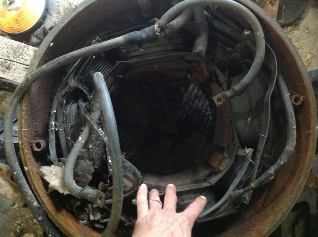
. If I leave the interpoles, i could make it an 8 pole.
            I am going to start making a rotor, where caps can be hidden inside. I've been, and still am,looking for another commutator.

            Machine
            Hi Machine, one ambitious project which will require lot of work and planning. After collecting data on my dual pentagon asymmetric motor, I too will start working on the IMPERIAL MOTOR. I now will have access to all the update knowledge bank to rely on. Many many thanks to you all IMPERIAL MOTOR GUYS.

            Warmest regards

            light

            Good luck

            Comment


            • Originally posted by Cornboy 555 View Post
              Hello Erfinder, Prompt, and to a lesser extent, Farmhand,---- Jeessuss,---- UFO, takes some time out and you guy's move in, What are you?

              @ Erfinder, i have watched your videos, and i think you have a very valid point or two, but we here would like you to show us how to rewind, or reconnect, the imperial motor to your specifications, so it will use less input under load, and speed up at the same time!!.

              This thread is about practical replication and building, not just theory.

              A simple diagram, or sketch will do, no one here is going to send you an Imperial to modify!

              My interest is purely in Vehicle Traction motors, and they require heavy torque, right from idle, like these motors show.

              @ Prompt, 240watts to get 400Watts, Hmmm!!, i think you will find later on with testing, that what UFO has said, regarding the linear nature, of the progression, as you load this design, will speak quite clearly for itself.

              @ Farmhand, i have followed your posts for the last two years, including the Don Smith thread,( mainly because you are a fellow Aussie) and you have made some very nice Tesla transformers, and achieved some nice results, Please, just because you haven't found over unity in anything you have achieved, Don't let it cloud your judgement, with Negativity, you are a valuable asset, to all here.

              You have said, I will give it, "Three Years", so sit back and watch, and if you can add something that you think may be positive, and help all us,
              " struggling" on this thread, please chime in.


              I mean no Malice, or bad intentions in what i have posted, Let's all work together, towards a common goal.

              Warm Regards Cornboy.
              Hello Cornboy lets concentrate our focus on our projects and not be distracted.
              If these dis-tractors, ever knew how to achieve over-unity of energy they will not be telling us how. They will be too busy getting it ready for themselves and dreaming how to amass their million$ and then more $$, $$$$, so on. That's their nature and so be it.

              Like you I too played with the Tesla / Don Smith type of devices but OU was not yet observed. For now they are on hold as I am like the rest of us here concentrating on the Asymmetric Motors, Generators, and The Radiant Energy. I must say, I was greatly impressed first time I saw UFOPOLITIC's work. Greatest gift we have here is our open source nature of sharing and doing things.

              For historical reasons, here is picture of one of my Tesla devices for now in moth balls. All those HV components are pricey as you know as well.


              https://www.dropbox.com/s/r9oc46q78k...2021.40.56.jpg


              As for time frame for over unity of energy, I will say, we will reach there sooner than later. Again our strength lies in numbers and sharing open source nature of our members. It is greatest quality. The person who has
              gone beyond just the money, more money, is closer to GOD or Buddha nature. Yes we all need money to buy food, shelter and of course components for our R&D. Good luck to all our Friends.


              Warmest regards

              light

              Comment


              • Originally posted by Ufopolitics View Post
                @Machine:

                Here Mr Machine Alive...some more "Hints" to fly...so you could "relax" a bit... from heavy steel machines...

                [IMG][/IMG]


                Regards Friend


                Ufopolitics

                Hello UFOPOLITICS, Machine, this appears to be practical realization of the concept of rotor-less machine you presented some while ago.
                Please tell us more about this machine puzzle.


                Good luck

                Warmest regards

                light

                Comment


                • Freely.

                  Originally posted by Lightworker1 View Post
                  Hello Cornboy lets concentrate our focus on our projects and not be distracted.
                  If these dis-tractors, ever knew how to achieve over-unity of energy they will not be telling us how. They will be too busy getting it ready for themselves and dreaming how to amass their million$ and then more $$, $$$$, so on. That's their nature and so be it.

                  Like you I too played with the Tesla / Don Smith type of devices but OU was not yet observed. For now they are on hold as I am like the rest of us here concentrating on the Asymmetric Motors, Generators, and The Radiant Energy. I must say, I was greatly impressed first time I saw UFOPOLITIC's work. Greatest gift we have here is our open source nature of sharing and doing things.

                  For historical reasons, here is picture of one of my Tesla devices for now in moth balls. All those HV components are pricey as you know as well.


                  https://www.dropbox.com/s/r9oc46q78k...2021.40.56.jpg


                  As for time frame for over unity of energy, I will say, we will reach there sooner than later. Again our strength lies in numbers and sharing open source nature of our members. It is greatest quality. The person who has
                  gone beyond just the money, more money, is closer to GOD or Buddha nature. Yes we all need money to buy food, shelter and of course components for our R&D. Good luck to all our Friends.


                  Warmest regards

                  light


                  Hello Light,i agree , lets keep on track, and thanks.

                  I have a collection like yours also, with large 4000v can capacitors and a cupboard full of other HV components, there is no better way to learn, than to do the experiments.

                  When UFO came along, and started to clearly explain, with practical ideas and replication schematics etc, it was like a breath of fresh air, and when the first thread, led to the motor thread, well that was the clincher for me.

                  Mechanically switching my plastic pulse motors, with the diode set up, showed just how much energy could be taken from an inductor, at switch off. To follow on from that to heavy torque, iron core traction motors, is going to be very rewarding i am sure.

                  We do, all need to stick together, and share all or ideas and accomplishments, here freely.

                  Warm Regards, Cornboy.

                  Comment


                  • Originally posted by Lightworker1 View Post
                    Hello Cornboy lets concentrate our focus on our projects and not be distracted.
                    If these dis-tractors, ever knew how to achieve over-unity of energy they will not be telling us how. They will be too busy getting it ready for themselves and dreaming how to amass their million$ and then more $$, $$$$, so on. That's their nature and so be it.

                    Like you I too played with the Tesla / Don Smith type of devices but OU was not yet observed. For now they are on hold as I am like the rest of us here concentrating on the Asymmetric Motors, Generators, and The Radiant Energy. I must say, I was greatly impressed first time I saw UFOPOLITIC's work. Greatest gift we have here is our open source nature of sharing and doing things.

                    For historical reasons, here is picture of one of my Tesla devices for now in moth balls. All those HV components are pricey as you know as well.


                    https://www.dropbox.com/s/r9oc46q78k...2021.40.56.jpg


                    As for time frame for over unity of energy, I will say, we will reach there sooner than later. Again our strength lies in numbers and sharing open source nature of our members. It is greatest quality. The person who has
                    gone beyond just the money, more money, is closer to GOD or Buddha nature. Yes we all need money to buy food, shelter and of course components for our R&D. Good luck to all our Friends.


                    Warmest regards

                    light
                    "Judge not lest ye be judged..."

                    I didn't come here to pick a fight, and engage in name calling... You have no idea what my intentions are...so it would be refreshing if you kept your "opinions" regarding what you "assume" my goals and ambitions are to yourself...I had a very refreshing conversation with cornboy, I have new found respect for him for he demonstrated that he is prepared investigate tangents...

                    As for over-unity....I made no claims...and if I were in the position to make such a claim, I still wouldn't....to label me as a dis-tractor is an insult to me and all free thinking individuals of the alternative energy community....If this community is going to ever experience the so called over-unity and or free energy, it will come from a joint full spectrum effort, no one individual or group of individuals has all the pieces....not the groups in the peanut gallery anyway...we are the peanut gallery......

                    Regards
                    Last edited by erfinder; 07-05-2013, 06:01 AM.

                    Comment


                    • Good Work.

                      Hey Light, i got some time to watch your vids, thanks so much for your time, and meticulous testing, it will be great to apply your test setup to the imperial, can't wait.

                      Thanks for sharing your work and findings here, for all to see!

                      Warm Regards Cornboy.

                      Comment


                      • Test run on my QP10 motor

                        Ufo,
                        Good news on your quad Pentagon ten pole design. Did a quick test run on 12 V On one brush set only. Seemed to be doing about a few thousand RPM. I will be putting the other brush sets together when I get off vacation. I completed my test using the car's battery. I was using a UPS computer battery but it seemed like it couldn't take the load and something Went on it.
                        Up, Up and Away

                        Comment


                        • Kogs Question re 10 pole 4 stator MY1018 motor

                          G'day UFO
                          I know you are very busy with setting up your new thread but Please I was interested in wiring a 10 pole 4 stator with 2 pairs of brushes the only winding diagram similar is this one


                          I think I read somewhere that you said that if wound serially it worked better

                          I have a MY1018 Motor the same as above BUT I do not want to put the extra commutators on as I want to keep it's length and I don't really have the space to mount an enlarged one I thought that I could use the 4 brushes at one end to make 2 pairs of brushes

                          Please you can advise me how to wind it

                          I would like to finish this project before I do the Imperial motors
                          Unfortunately More work has come my way it will slow things down a bit but I need the money to pay for my parts etc
                          Kindest
                          Regards

                          Still working at it

                          Comment


                          • Start PWM...

                            Originally posted by JohnStone View Post
                            @UFO: regarding PWM discussion:
                            At what low frequency shall the pulse train start in order to get the motor speed up correctly from state of 0 rpm. It might be essential if the motor starts under load.
                            A: lowest possible
                            B: frequency of intended continuous operation
                            C: something else ....


                            JS
                            Hello and Welcome back My Friend John Stone!

                            Glad you had such exciting trip!...Did you see any UFO's in the Alps sky?
                            Hope everything would be fine with your family.

                            Now John, this Motors draw quite some amps at start up from zero, to brake the mass inertia of rotor weight, and as individual coils start to retain some inner energy, then amp draw starts to reduce.

                            Therefore, I recommend to start with either (B) [Frequency of Intended Operation] or a (C) based on a higher/Longer "On Time" in the PWM , IF Motor is connected to a Mechanical Load. As is the case of Imperial-Mecc Alte, and Generator head not loaded Electrically, but having in mind that Motor would be also spinning the gen Rotor weight through shaft coupling.

                            And on a second connection type:

                            If Motor have its Output connected to an electrical load, I recommend to turn those Out Gates off, till Motor develops a constant and robust operation, then load it.


                            Warm Regards


                            Ufopolitics
                            Principles for the Development of a Complete Mind: Study the science of art. Study the art of science. Develop your senses- especially learn how to see. Realize that everything connects to everything else.― Leonardo da Vinci

                            Comment


                            • Great work Light!!

                              Originally posted by Lightworker1 View Post
                              Hello Johnstone, great to see you back. Our prayers are for a very speedy recovery for your wife's health and wish you both peace and strength during these very difficult times. I will also look into DASHBOARD. Looks interesting. Perhaps it is similar to LabView, I do not know for sure.

                              Hello Dear Friends. I am going to present couple short videos of the progress so far with the goldmine asymmetric motor, the test rig and the development of the Arduino sensor data processing program.

                              To recap: This dual pentagon asymmetric motor has rotor with five chip capacitors in parallel, that is, each coil has one capacitor in parallel.
                              As such, some form of resonance effects are expected.

                              https://www.dropbox.com/s/avcjwqh6q8...2011.44.22.jpg


                              The graph towards the end shows some interesting features.
                              For example, Vout at places is over taking Vin.
                              I will be exploring that aspect in some detail in the days coming.

                              https://www.dropbox.com/s/kqyq5t8h1r..._m3f6ba0e0.jpg


                              First Video: Calibration - How IR Thermometers Behave and processing captured Arduino sensor data.

                              https://www.dropbox.com/s/c0bgzxsyq5...s%20Behave.mp4


                              Here is the spread sheet displaying the captured data and graph

                              https://www.dropbox.com/s/qiut5untp3...20filtered.xls


                              second Video: Exploring Dual Pentagon Test Rig

                              This is just a hand-held camera video shoot. Sorry about video not being stable.

                              https://www.dropbox.com/s/pn8xshekxb...otor%20rig.mp4


                              Third Video: Final Rig Setup and getting ready for the Real Experimental Work

                              This is the test rig in its more or less final form. The only thing I might want add is a STAIR CASE SIGNAL to PSU to automatically increment PSU Voltages from LOW to HIGH in steps.

                              https://www.dropbox.com/s/bu51qvv0xj...0on%20Vout.mp4


                              Here are copies of two programs I have been using. At present they are in
                              their development stage, that is they need to to be cleaned properly with more extensive comments etc.


                              First program Arduino sketch must be uploaded into Arduino such as UNO or Mega, using Arduino IDE

                              https://www.dropbox.com/s/whqk5eutbu..._PSU_ShutD.ino

                              Second program is the processing that looks at the data coming over the serial port (USB). This is one that displays the information on the screen.

                              https://www.dropbox.com/sh/18fnkcenn9izlrg/IE1ggAm89x

                              Here is a nice tutorial on this subject:
                              Tutorial 07 for Arduino: I2C Communication and Processing by Jeremy Blum

                              https://www.youtube.com/watch?v=GJX0BRUagCg


                              The processing software can be downloaded from

                              Processing.org

                              for your appropriate hardware.

                              So here it is all for now, I hope it useful, and if there are any questions please feel free and I will try to answer as best I can


                              Warmest regards

                              light

                              Hello Light!


                              Great work my friend!, excellent running videos and whole set up!.

                              When you run next tests on this Set up, see if possible to measure Amps at start and Amps after is running...
                              Then redo it again (disconnecting Motor from PSU completely) and seen a comparison from previous tests.

                              You will then realize that Caps assist Coils to retain energy...so, every "following" start, will draw less amperage than first one...

                              Also, need to show through text titles on each V meter, which one is what...V1=Input, V2=Output, etc,etc
                              Intended for others to understand what's going on...

                              Very sophisticated analysis on RPM's and Temperature behavior my friend, I am very glad it is working like a charm!

                              Warm Regards


                              Ufopolitics
                              Principles for the Development of a Complete Mind: Study the science of art. Study the art of science. Develop your senses- especially learn how to see. Realize that everything connects to everything else.― Leonardo da Vinci

                              Comment


                              • Hello Kogs!

                                Originally posted by iankoglin View Post
                                G'day UFO
                                I know you are very busy with setting up your new thread but Please I was interested in wiring a 10 pole 4 stator with 2 pairs of brushes the only winding diagram similar is this one


                                I think I read somewhere that you said that if wound serially it worked better

                                I have a MY1018 Motor the same as above BUT I do not want to put the extra commutators on as I want to keep it's length and I don't really have the space to mount an enlarged one I thought that I could use the 4 brushes at one end to make 2 pairs of brushes

                                Please you can advise me how to wind it

                                I would like to finish this project before I do the Imperial motors
                                Unfortunately More work has come my way it will slow things down a bit but I need the money to pay for my parts etc
                                Kindest
                                Regards

                                Still working at it
                                Hello My Friend Kogs,

                                Kogs, I really do not understand what you are trying to do...

                                If You want to use just Two Brushes SETS, instead of Four Sets with Four Stators...I believe Donald Haas have done that and it worked out for him...

                                Also Sampojo is working on this Design...check their posts on this subject.

                                What I do not understand is the underlined and bold letters part, above...

                                "BUT, I do not want to put the extra commutator(s) on"

                                You meant, you just want to use ONE Commutator?...Then add there the Four Brushes to the same Comm?

                                Sorry, but I am lost...

                                Warm regards


                                Ufopolitics
                                Principles for the Development of a Complete Mind: Study the science of art. Study the art of science. Develop your senses- especially learn how to see. Realize that everything connects to everything else.― Leonardo da Vinci

                                Comment

                                Working...
                                X